Introduction to Ladder Logic Programming Series


Ladder Logic Programming has been derived from relay logic electrical circuits. This language of PLC programming is called ladder logic or LD as it looks like a ladder of many rungs. Each rung represents a line of logic by connecting inputs logically to form a condition on which the output is determined to be on or off. By completing this article, you will have enjoyed understanding the basics of the LD programming language. Consequently, you will have been able to read a ladder logic code and translate the logic in your mind or the electrical circuit between your hand into ladder rungs.
Relay Logic Control vs PLC
Relay logic control was the old fashion classic control in which input switches and sensors are connected between the hot voltage and relays’ coils to energize these coils and in turn, activate their contacts and thereby connect or disconnect the actuators i.e., motors, lamps, valves etc. You cannot imagine how complicated that control was besides its limitation in functionalities. In addition, it has a huge number of wires and components to achieve a simple logic. Furthermore, there are no chances to change the logic or the sequence of operation without destroying, rebuilding, and rewiring everything from scratch. When it comes to troubleshooting and maintenance, you should be very patient and generous for your time and efforts to pay to keep tracking hundreds of wires and checking up a bunch of components to figure out the problem.
To image the difference between old fashion classic control and PLC, figure 1 shows the case of a very simple process that contains four motors, and four sensors that are connected via four relays and a timer for performing a very simple logic. Let’s say we need to run motor 1 at the start and after a while, we plan to run motor 2 and 4, and at last run motor 3 considering one constraint that no more than two motors can run simultaneously. In addition, sensors will be used as protection to emergency stop motors at any time. Now on the left of the figure, you can see the relay logic control. you can imagine how many components and punch of wiring work for connecting sensors, timers, relays, and motors. On the other hand, PLC-based control shown on the right, you can notice only the PLC and input devices and output actuators are connected to the PLC. To sum up, the number of wires is reduced significantly, the effort of wiring is immensely reduced. In addition, when it comes to modification of logic or process sequence you need to destroy all old wiring and start over rewiring according to the new requirements while you can do this by modifying the program in PLC without touching the wiring. To sum up, PLC reduced the number of components, wires, time of implementation. In addition, the processing is faster thanks to PLC processing and modification becomes programmatically.

How PLC works?
Before opening the door to enter our tutorial on ladder logic programming, let’s have a brief idea about how PLC works and what ladder logic program has to do with PLC. Well! Let me briefly say that PLC has input modules, output modules, and a processor. The input modules are connected to input switches and sensors while the output modules are connected to actuators i.e., motors, valves, lamps. And for sure processor runs the ladder logic program that we going to learn here! In the below figure, I have tried to clear it visually.

The processor works in scan cycles, in each scan cycle, it gazes into all inputs and records them in its memory and then executes the ladder logic to determine the new status of outputs and update them and go to the next cycle, and so on. So now you can tell me what ladder logic has to do with this? That is great to hear you say that it is the logical connection between inputs to determine the output status. I really can not wait to go ahead and hit the nails on the head and open the door to let us get started with our tutorial about ladder logic programming. In the below figure, I have shown PLCs of different manufacturers:

Ladder Logic Programming
Each programming language has a structure and building blocks. The building block of a ladder program is a rung. Yes, rungs of a ladder go step by step to do the designed logic and repeat every scan cycle. Each rung forms a complete piece of logic like one complete circuit. so let us go to know how to form this rung and get to know what components of these rungs and how they are connected logically.
Understanding Rung in Ladder Logic
- In the below figure, I have shown a single rung of ladder logic programming.
- It's the simplest ladder logic rung and it has Input on the left side and Output on the right side.
- The ladder logic rung is composed of two parts:
- The Left Part represents the condition on which the output is determined to be true or false. This part is a combination of contacts or inputs in series for making AND logic or in parallel to perform OR logic.
- The Right Part is the output coil or a trigger signal to start timer or counter as we going to elaborate later.
- Ladder Logic works from left to right and thus according to this rung, if Input is LOW, the output will remain LOW, and if Input gets HIGH, the Output will also get HIGH.

- So, you can say the above rung is actually representing a simple electrical switch i.e. if we turn ON the switch, Lamp(Output) will get lightened up and vice versa.
- In this tutorial, I am just giving the overview, so if you are not getting all the things, don't worry, as, in the upcoming tutorial, we will design them on the simulator again & again.
- Inputs in LAdder Logic PRogramming are normally coming from switches, pushbuttons, sensors etc.
- Inputs come in two configurations:
- Normally Open (NO): shows the input initially at a LOW state and gets HIGH by pressing or activating.
- Normally Closed (NC): It's initially is at a HIGH state and gets LOW when it is pressed.

Multiple Rungs in Ladder Logic
In the above section, we have designed a simple ladder logic program, where we have used just a single input to control our output. These contacts/inputs in their two configurations can be connected in series (AND logic), parallel (OR logic), or negation (NOT) to form logical combinations. In the below figure, I have designed three rungs of Ladder Logic, let's understand them one by one:
- 1st Rung: I have used two Normally Open Contacts in the first rung, so you can think of it as an electrical line having two switches in series. So, the output will get current, only if both switches are on/closed. So, it's actually an AND Gate in Ladder Logic i.e. output will get HIGH only if all the inputs are HIGH.
- 2nd Rung: In the second rung, I have used both normally open and normally close contacts, so if Input1 gets pressed, the output will get HIGH, but if Input2 gets pressed(actually open/off) then Input1 won't be able to turn ON the Output. So, you can think of Input2 as a master switch.
- 3rd Rung: Now you must have understood by now that I have designed an OR Gate in this rung, so if any of these inputs get HIGH, the Output will get HIGH as well, because Inputs are connected in parallel.

- When two or more inputs are connected in parallel in order to design OR logic, it's called rung branches.
Slightly Complex Project in Ladder Logic
In the below figure, you can see a slightly complex Ladder Logic Program, having different components, let's discuss them one by one:
- The output coil may have the character “S” to show the output going to be set to true until a reset signal is received.
- Furthermore, it could have the character “R” to show the reset status of the output to false.
- Character “P” in the middle of contact shows this is the rising edge of input when it changes from false status to true.
- On the other hand, character “N” in the center of contact shows the falling edge of the input when it changes from true to false.
- And the timer and counter blocks are shown in the last two rungs to show the initiation of timer and counter.
- All these components will be described in detail when the tutorial train reaches its station. So do not worry about them at this point.

Logic Gates & Ladder Logic
If we define the ladder and its building blocks which are rungs how about the word “logic” the second word in ladder logic? Well! Table 1 reviews the logic gates and their truth table. For you to expect the incoming status of your output based on the status of the inputs and the logical combination pattern. to decide the results logic output ( RLO) which is the status of the logical combination of contacts that precede the output coil. For instance, the AND gate/logic function is applied between two or more inputs when all of the inputs should be true to get the output to be true. On the other hand, the OR gate/logic function between two or more inputs is used when we need at least one of the inputs to be true to get the output to be true.

Reading ladder logic rung
- The reading starts from left to right to complete one rung and then from up to down rung by rung till the end of the program.
- You can imagine that you read the ladder program instead of PLC.
- First, you scanned the input and update the input memory and then scan each rung from most left to right to evaluate the RLO and set the new status of the output based on the determined RLO.
- After completing one rung, plc move to the next rung from top to bottom till the last rung in the program at that point one scan cycle is done and move to the next scan cycle and so on.
- You can compare Ladder Logic with electrical wiring logic, as both follow the same pattern.

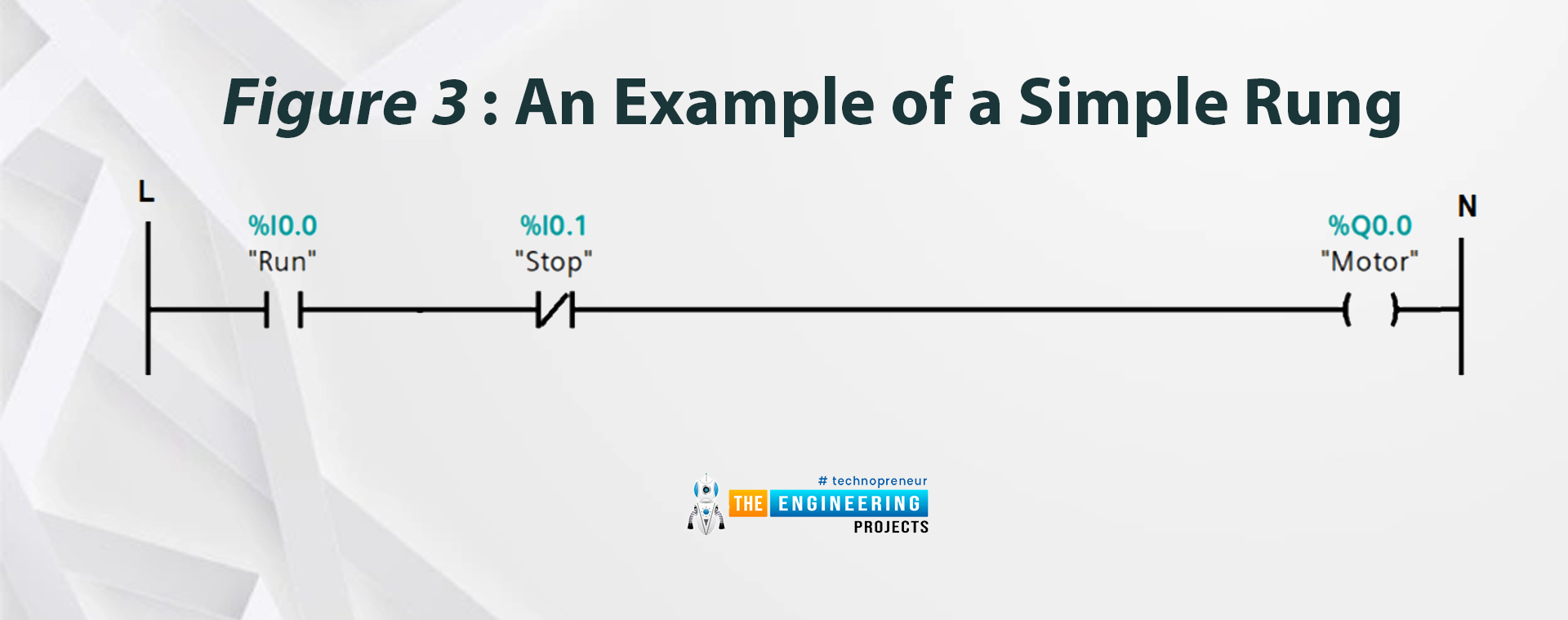
Let’s see one simple example to understand the reading ladder logic program. Figure 3 shows a very simple complete ladder logic rung that connects a normally open pushbutton to start a motor and another normally closed pushbutton to stop the motor. You can see each component of the inputs and outputs should have an address to be uniquely identified by PLC. For instance:
- The normally open push button named “Run” takes an address of I0.0 which is linked to the first input channel of the first input module in PLC.
- The normally closed push button to stop the motor called “stop” takes the address I0.1 which is physically connected to channel 2 in the first input module of the PLC.
- On the other hand, the output coil takes address Q0.0 which is the first output channel of the first output module in PLC.
- So clearly when you press your push button "RUN" it will connect the motor output coil to the positive line and hence get energized.
- But when press the "STOP" button, you will disconnect the motor coil from electricity and hence stop it.

What’s next ???
Now, how do you see your progress so far? I can see you are doing progressively and that’s great. However, we still have a lot to learn to master ladder logic programming. However, we need to set up the environment for simulating a Ladder logic program to be able to validate our programs and enjoy seeing its execution typically as if we have a PLC controller and to verify how far our designed ladder performance matches the real-time execution on the simulator.