Hi friends, today we are going to learn a good technique to run multi outputs in sequence. In another word, when we have some output that is repeatedly run in sequence. In the normal or conventional technique of programming we deal with them individually or one by one which takes more effort in programming and much space of memory. So instead we can use a new technique to trigger these outputs in sequence using one instruction which will save the effort of programming and space of memory. In this article, we are going to introduce how to implement sequencer output instruction. And practice some examples with the simulator as usual. Before starting the article, we need to mention that, some controllers like Allen Bradley have sequencer output instruction and some has not like Siemens. So we are going to give one example for each case showing how to code the equivalent to the sequencer output instruction in the PLCs that does not support this instruction.
Sequencer output instruction
Figure one shows the block diagram of the process. The instruction takes the input data from the file, array, and data block and sequentially relays it to the outputs to trigger them sequentially.
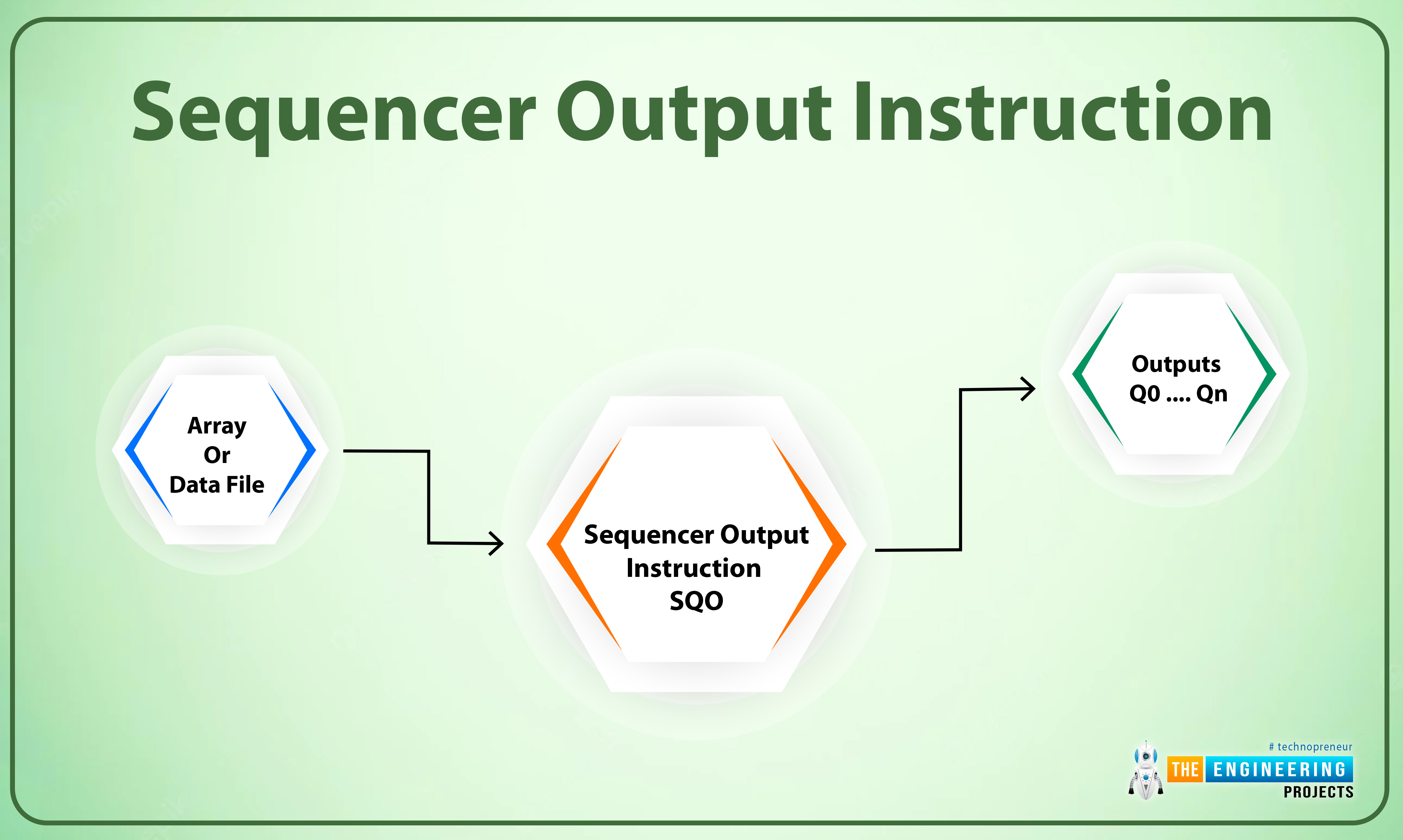
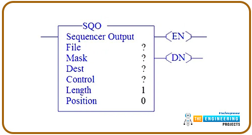
Figure 2 shows the block of the sequencer output instruction showing input and output parameters. The file parameter is the first input parameter showing the address of the reference sequencer file. In addition, the mask input is to receive the address of the mask or the data block of which the instruction will move the data sequentially before relaying it to the output. Furthermore, the dest parameter is an output parameter that shows the address of the output to which the sequence bits will be applied. And the control parameter is the storage words for the status of the instruction, the file length, and the position of the pointer in the data file or array. Also, the length parameter holds the number of steps to move in the data file to the output destination sequentially. And position parameter holds the location of the pointer in the data file.
Block description and example of the sequencer output instruction
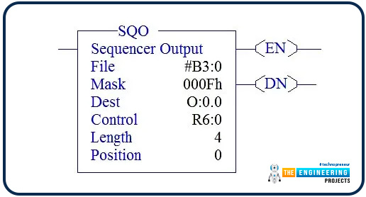
Figure 3 shows an instance of sequencer output instruction QSO. The QSO instruction steply moves through the input data file or array or data block and transfers sequentially the data bits from the data file to the output (destination word) through the mask word. The status of the instruction can be shown in the DONE (DN) bit. You should notice my friends that after the data transition is done the position is reset to the initial position or the first step.
Ladder Logic Example
Now guys, let us move to the ladder logic coding. So how does that sequencer output instruction work in ladder logic? Well! Figure 4 shows a complete example of QSO instruction that is used in Allen Bradley to handle the sequencer output process, it shows one rung that has a start and stops push buttons from left to right at address I:0/0 and I:0/1 respectively to control the starting and stopping of the sequencer output processing. Next, you can see input I:0/2 which is used as a sequencer process flag to switch on or off the sequencer process. So, if the start PB is requested when no emergency stop and the sequencer on input is ON, the QSO is enabled and the data at address #B3:0 will be moved to dest at address O0:0 though the mask word at address 000Fh starting from position 0 with length 4.

Figure 5 shows the data file that the QSO uses to transfer sequence data bits to output. It shows the bits B3:0, B3:1, B3:2 & B3:3 are set to 1 for reference. So, when the sequencer ON input is set to high (I:0/2). The output Q:0/1 will be turned on based on the data in the data file shown in fig. 5. In that case, the length is 4 and the position is 1.
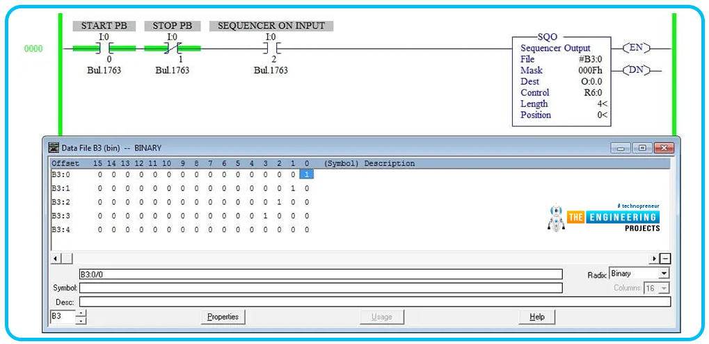
And when the sequencer flag I:0/2 is switched on next time, output O:0/2 will be switched ON. In that case, the length is 4 and the position is 2 as shown in Fig. 6.
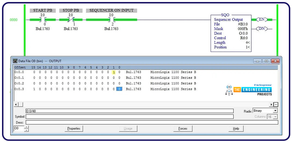
In the third time, the sequencer flag is turned ON, the output O:0/3 will be turned ON and the length and position are updated to 4 and 3 respectively as shown in Fig. 7.
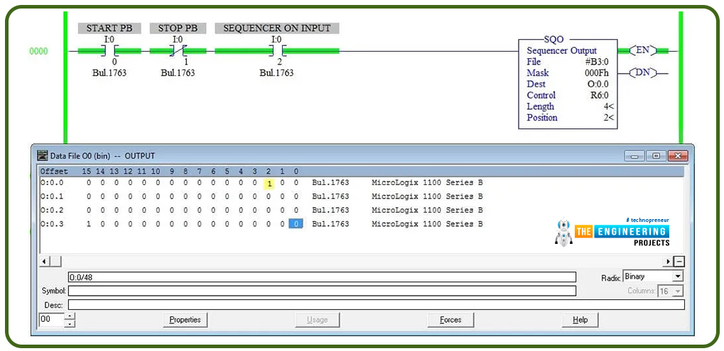
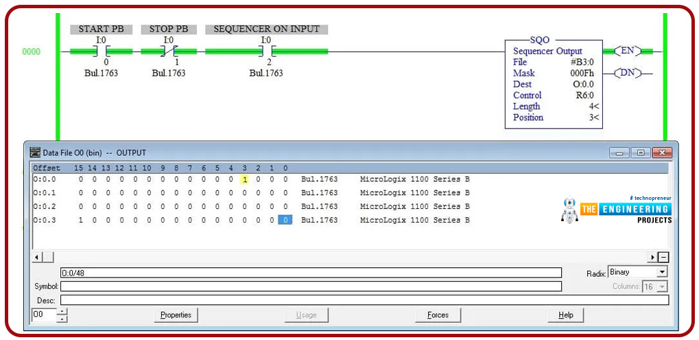
When it comes to the fourth time of switching the sequencer flag I:o/2, the output O:0/4 will be turned high and the position will be at 4 and length is 4 as shown in fig.8. At that time, the process is reset and position reset to 1.
The previous example shows how it is simple to control a bunch of outputs that are required to run in sequence with only one rung of the ladder program and using only one instruction which is QSO in Allen Bradley. This merit helps to save the memory space and time and efforts of programming and troubleshooting as well because the program will be shorter and more readable. However, still, some brands have not supported such instructions even the big names like siemens. That can not be counted as limitations but they are banking on there being a way to implement such logic. So, it is very beneficial for you guys to go implement together a piece of code (ladder logic) that is equivalent to such instruction for performing the function of sequencer output instruction in Siemens S7-1200 using our simulator.
Ladder logic code for SQ0
As you guys see the sequencer output instruction is nothing but shifting the height value from right to left bit or right to left or even rotated shift for continuous operation. That drives our thinking to use the shift instructions in Siemens to perform this sequencer output instruction.
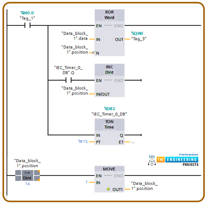
Figure 9 shows the rungs of a ladder PLC simple program that implements the sequencer output process. See guys how lengthy the logic we have to code to do the same function of single instruction QSO in Allen Bradley. Again, that is a drawback or limitation thing but the program is more lengthy and takes more effort and also memory it is consuming that way. Moving to the logic listed in Fig. 9, the first thing is using a rotated shift instruction that shifts through the data block bit by bit and applies to the output QW0. At the same time increment instruction is used to move through the data. Also, one on delay timer is used to do some delay to show up the sequencing process of activating the output sequentially. And the end, a comparison instruction has been used to check if the pointer or the position reached the last output coil to reset to the first position and so on.

Simulating the sequencer output ladder code
Figure 10 shows the simulation of the sequencer output ladder code before activating the processes by using M0.0, it shows the position is at 1 and the output QW0 is all zeros. So let us activate the sequencer output process by set M0.0 to high and see the output.
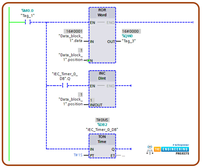
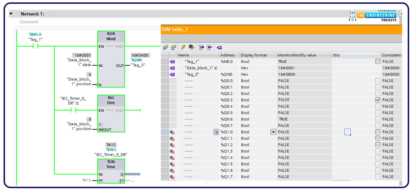
Figure 11 shows the process after activating the sequencer program and starting to switch on outputs sequentially. The figure shows the process reached the sixth output coil and the position set to 7 to point at the next output. The process continues to tell reach the last one and then the position set the first step.
What’s Next???
I am glad to have you guys following tell that point and I hope you see the importance of the sequencer output technique in reducing the effort of programming and saving memory. Next time will take a tour with the bitwise logic operator and how they are utilized and how they work in the ladder program with given examples and for sure simulation to practice their usage. So let’s meet then and be ready.


