Hello friends, I hope you all are doing great. Today, I am going to share the new TCS34725 Sensor Library for Proteus V1.1. The TCS34725 from ams (TAOS) is a small RGB colour sensor: it measures the red, green, blue and clear light that comes back from an object, and it is best known on the blue breakout board with the bright white LED. With this TCS34725 Sensor Library for Proteus, you pick the object's colour with presets, sliders or a click on a colour palette, and your Arduino reads it over I2C with the same Adafruit TCS34725 library you use on real hardware.
TCS34725 Sensor Library for Proteus
Latest version: V1.1 (September 2026, this tutorial)
Other light sensors: LDR · BH1750
Helping Tools
- Serial Monitor Advance: a serial terminal window for the UART of your board
- Serial Monitor Expert: the serial monitor with extra debugging tools
- LCD Library for Proteus V3.0: 16x2, 20x4 and I2C LCDs to show your readings
Version 1.1 replaces the first version of this post. You now get two devices: TCS34725 Simple, with a control panel on the schematic, and TCS34725 Advance, with a pop-up window and four measured sensor test tools. The board's white LED now has its own switch, and the new TCS34725 Arduino Proteus demo runs on two Arduino UNOs with a red-detector LED and commands for the gain and the integration time, shown in the compact Simple interface of our TEP Serial Monitor. Have you read version 1.0? Then jump to "What's New" below.
NOTICE: This library is very special to our team. Our TCS34725 model has the chip's register map with its command byte, the integration time with its saturation, the four gains, the wait timer and the clear-channel interrupt with the INT pin, and it speaks I2C to the unmodified Adafruit library. It took our team a lot of hard work, many test runs and many design changes. Your feedback is the fuel that keeps us going, so please tell us what you think in the comments below or in the TCS34725 Library board of our forum. And if our free libraries help you, you can buy us a coffee. So, let's get started with the TCS34725 Sensor Library for Proteus:
What is the TCS34725 Colour Sensor?
The TCS34725, made by ams (TAOS), is a digital colour sensor. It has four kinds of light-sensing elements: three behind red, green and blue filters, and one without a colour filter, the clear channel. Integrating analog-to-digital converters (ADCs) turn the light of each channel into a number, the count, and an infrared-blocking filter on the chip reduces the infrared part of the light. Your Arduino reads the four counts over I2C, the 2-wire bus with a clock line (SCL) and a data line (SDA). For the chip's registers and timing, see the TCS3472 family datasheet, which covers the TCS34725.
The clear channel measures all the light, without a colour filter. It is not an "alpha" or transparency value. And the sensor never says "red" or "blue": the colour name is a decision your sketch makes from the counts. On the common breakout, a white LED sits next to the sensor and lights the object a few millimetres in front of it.
The TCS34725 at a Glance
| Feature | Value |
|---|---|
| Measures | Red, green, blue and clear light, as raw 16-bit counts (RGBC) |
| Interface | I2C, standard and fast mode, at the fixed address 0x29 |
| Chip ID | Register ID (0x12) = 0x44 |
| Integration time | 2.4 ms steps, from 2.4 to 614.4 ms (register ATIME) |
| Gain | 1x, 4x, 16x or 60x (register CONTROL) |
| Saturation | 1024 counts per 2.4 ms step, at most 65535 |
| Wait time | An optional pause between results (WTIME, 12 times longer with WLONG) |
| Interrupt | The clear channel outside a low and a high threshold, with a persistence filter; INT pin active low |
| Breakout pins | LED, INT, SDA, SCL, 3V3, GND, VIN (seven pins) |
| Supply | The chip: 2.7 to 3.6 V; the breakout has a 3.3 V regulator, so VIN takes 3.3 V or 5 V |
TCS34725 Terms You Will See in This Article
| Term | Meaning |
|---|---|
| RGBC | Red, green, blue and clear: the four channels |
| Count | The raw ADC result of one channel; not 0 to 255 like a colour code |
| Integration time | How long the chip collects light for one result |
| ATIME | The integration register: 256 - ATIME = the number of 2.4 ms cycles |
| Gain | The analog amplification, 1x to 60x (register CONTROL) |
| Saturation | The highest count the integration time allows; a brighter light is clipped to it |
| AVALID / AINT | STATUS bits: a valid result is ready / the clear-channel interrupt is set |
| PERS | Persistence: how many results in a row must be outside the thresholds |
| Command byte | The first byte of every I2C write: the register address and the mode (repeated byte, auto-increment or a special function) |
| Hue | The colour's angle on the colour wheel, used by our Colour test |
How the TCS34725 Turns Light Into Counts
Integration Time and ATIME
The chip collects light for a set time and then stores the four counts. That time is 2.4 ms x (256 - ATIME). The demo uses ATIME = 0xEB, which is 235, so 256 - 235 = 21 cycles and 21 x 2.4 = 50.4 ms. The Adafruit constant is called TCS34725_INTEGRATIONTIME_50MS, but the real time is 50.4 ms. A longer integration collects more light: more counts, but fewer results per second.
Gain
The gain amplifies the signal before it is counted: 1x, 4x, 16x or 60x. Four times the gain gives four times the counts, as long as nothing saturates. The demo starts with 4x.
Saturation: the Count Ceiling
Each 2.4 ms cycle can add at most 1024 counts, and a 16-bit register holds at most 65535. So the ceiling is the smaller of 1024 x cycles and 65535: 21504 at 21 cycles (50.4 ms), and 65535 from 64 cycles (153.6 ms) up. A channel at the ceiling is clipped, and its count no longer tells you how bright the light is.
The Counts in Our Model
Our model takes the object's colour as three numbers from 0 to 255 (RED, GREEN, BLUE) and a BRIGHTNESS in %. At 50.4 ms and 4x gain, a channel at 255 and 100 % gives 10000 counts before clipping, so:
count = 10000 x input / 255 x brightness / 100, then x cycles / 21 and x gain / 4
The start colour is 255, 64, 0 at 50 %. Red gives 10000 x 0.5 = 5000, green 64 / 255 of that, 1254.9, which rounds to 1255, and blue gives 0. The clear channel is the sum of the unrounded parts: 6255. That is why the demo prints R:5000 G:1255 B:0 C:6255 and not 255, 64, 0. The clear sum is a simplification of our model; a real sensor has its own clear response.
White at 50 % gives 5000 on every colour channel and 15000 on clear. At 100 %, every colour gives 10000, and the clear sum of 30000 is clipped to 21504. So the clear channel saturates first, while the colours still look fine.
The White LED
The breakout's white LED lights the object, so the sensor sees the object's colour and not only the room. In v1.1, the new LED property switches it: 1 = on (the default) gives exactly the v1.0 counts, and 0 = off leaves the object in the ambient light only. In our model, that ambient light is 25 % of the light with the LED (a model value), so every count drops to a quarter.
The Clear-Channel Interrupt and the INT Pin
The TCS34725 can watch the clear channel for you: set a low and a high threshold (AILT, AIHT) and the persistence (PERS), and enable the interrupt with AIEN. The INT pin then goes low while the interrupt is active, until the sketch clears it with a special-function command byte (Adafruit: setIntLimits(), setInterrupt(), clearInterrupt()). The demo leaves INT open, but the model has it, and the amber INT LED shows it.
What's New in TCS34725 Sensor Library for Proteus V1.1
If you used version 1.0, here is what has changed:
- Two devices in
TEPTCS34725.LIB: TCS34725 Simple (TCS34725TEP, the v1.0 device) and TCS34725 Advance (TCS34725ADVTEP) with a pop-up window. - A redrawn, live board: the blue breakout with an animated colour view, PWR / I2C / INT LEDs (a TEP addition) and the live I2C address.
- Nine presets next to the v1.0 palette and sliders; the Simple panel closes with a red X.
- The white LED switch: the new LED property; on gives exactly the v1.0 counts, off leaves 25 %.
- An I2C log: every transaction decoded, and the SCL clock measured on the pin.
- Four measured test tools on the Advance.
- A two-UNO demo with the TEP Serial Monitor instead of the Virtual Terminal: a red-detector LED, a saturation level that follows the integration time, and the commands GAIN, TIME and HEX; every v1.0 output line is kept.
- The same chip model: the RGBC counts, timing, saturation and interrupt of v1.0 are unchanged.
- Lighter package: about 1.64 MB, without the C++ source code and the AVR core archive.
And your old designs keep working. A design with the v1.0 symbol runs with the new model and shows the old palette panel; here, the v1.0 demo with the v1.1 DLL:
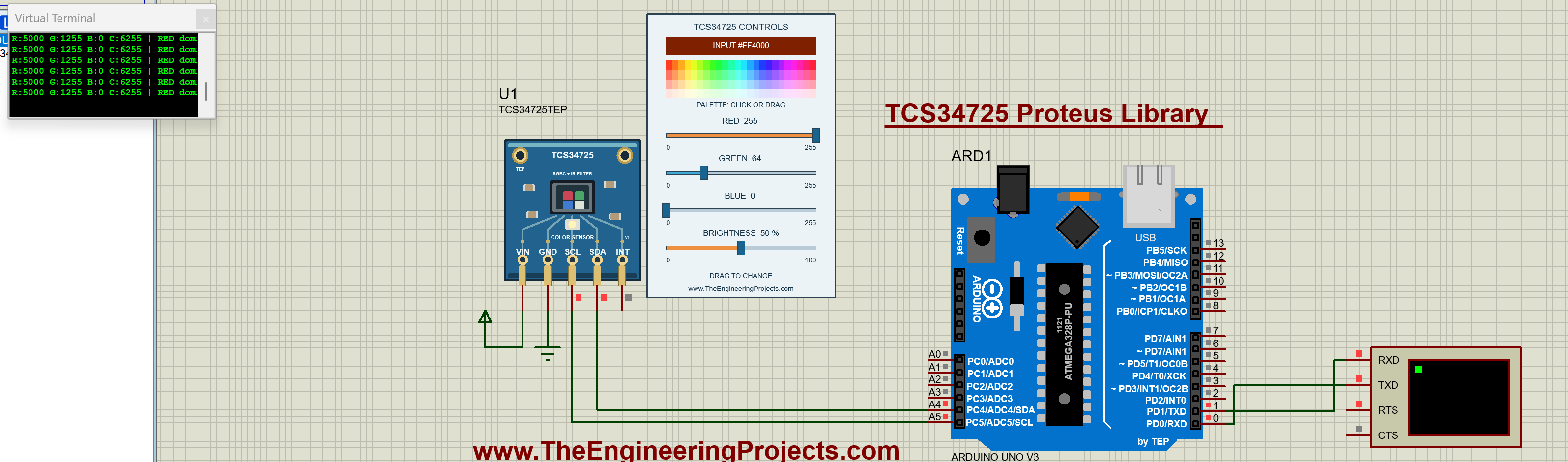
Re-pick the part from the library to get the v1.1 board, the presets and the red X.
TCS34725 Sensor Library for Proteus: Simple vs Advance
Both devices run the same model with the same properties; only the panel differs:
| Feature | Simple | Advance |
|---|---|---|
| Full TCS34725 model (RGBC counts, integration time, gain, saturation, wait, interrupt, INT pin) | ✔ | ✔ |
| Blue breakout board: live colour view, PWR / I2C / INT LEDs | ✔ | ✔ |
| Control panel on the schematic (nine presets, the v1.0 palette and sliders, what the sketch read) | ✔ | ✘ |
| Pop-up window you can move, resize and minimise | ✘ | ✔ |
| Sensor page: a large live view with its own palette, presets, click-sliders with - / + for all five inputs | ✘ | ✔ |
| I2C check, Timing, Step response and Colour test | ✘ | ✔ |
| TEP Dark / Light theme, text size, Help page with Copy diagnostics | ✘ | ✔ |
| Same device name as v1.0 (old designs keep working) | ✔ | ✘ |
Choose Simple to keep the controls beside your circuit, and Advance when your sheet is full or you want hard numbers about your sketch. The demo has one of each.
Download TCS34725 Sensor Library for Proteus
Click the button below to download TCS34725-Sensor-Library-for-Proteus-v1.1.zip (about 1.64 MB, without the C++ source code):
TCS34725 Sensor Library for Proteus V1.1- README.txt: a detailed guide to the files, the wiring, the model, the test tools and real hardware.
- Proteus Library Files:
TEPTCS34725.LIB(both devices),TEPSERIALMON.LIBand our Arduino UNO libraryArduinoV3TEP.LIB/ArduinoV3TEP.IDX. - Proteus Model Files:
TEPTCS34725.DLLandTEPSERIALMON.DLL. - Proteus Simulation:
TCS34725-ArduinoUnoV3.pdsprj,TCS34725_Demo.hex(both UNOs run it) and copies of both DLLs. - Arduino Code:
TCS34725_Demo.ino, the unmodified Adafruit TCS34725 library 1.4.4 with its five examples (BSD licence, in its license.txt) and Adafruit BusIO 1.17.4, which it needs (MIT licence, in its LICENSE).
No Proteus yet? Read How to Download and Install Proteus 7 and 8. New to libraries? Follow How to Install a New Library in Proteus.
How to Install TCS34725 Sensor Library for Proteus
- Close Proteus and extract the whole zip file.
- Copy the four files from Proteus Library Files into the LIBRARY folder, usually
C:\Program Files (x86)\Labcenter Electronics\Proteus 8 Professional\LIBRARY(on some PCsC:\ProgramData\Labcenter Electronics\Proteus 8 Professional\LIBRARY). - Copy
TEPTCS34725.DLLandTEPSERIALMON.DLLinto the MODELS folder. - Start Proteus, press P and search for TCS34725. You get the Simple and the Advance device (category Sensors > Color, as in v1.0).
Updating from v1.0? Replace TEPTCS34725.LIB and TEPTCS34725.DLL, and delete TEPTCS34725.IDX if there is one in LIBRARY. The DLL keeps its v1.0 name, so a v1.0 design keeps its v1.0 symbol and runs with the new model, with the v1.0 palette panel (no new board, no red X); re-pick the part to get the v1.1 board. Tested in Proteus 8.5; Proteus 7 is not supported.
The TCS34725 Board in Proteus
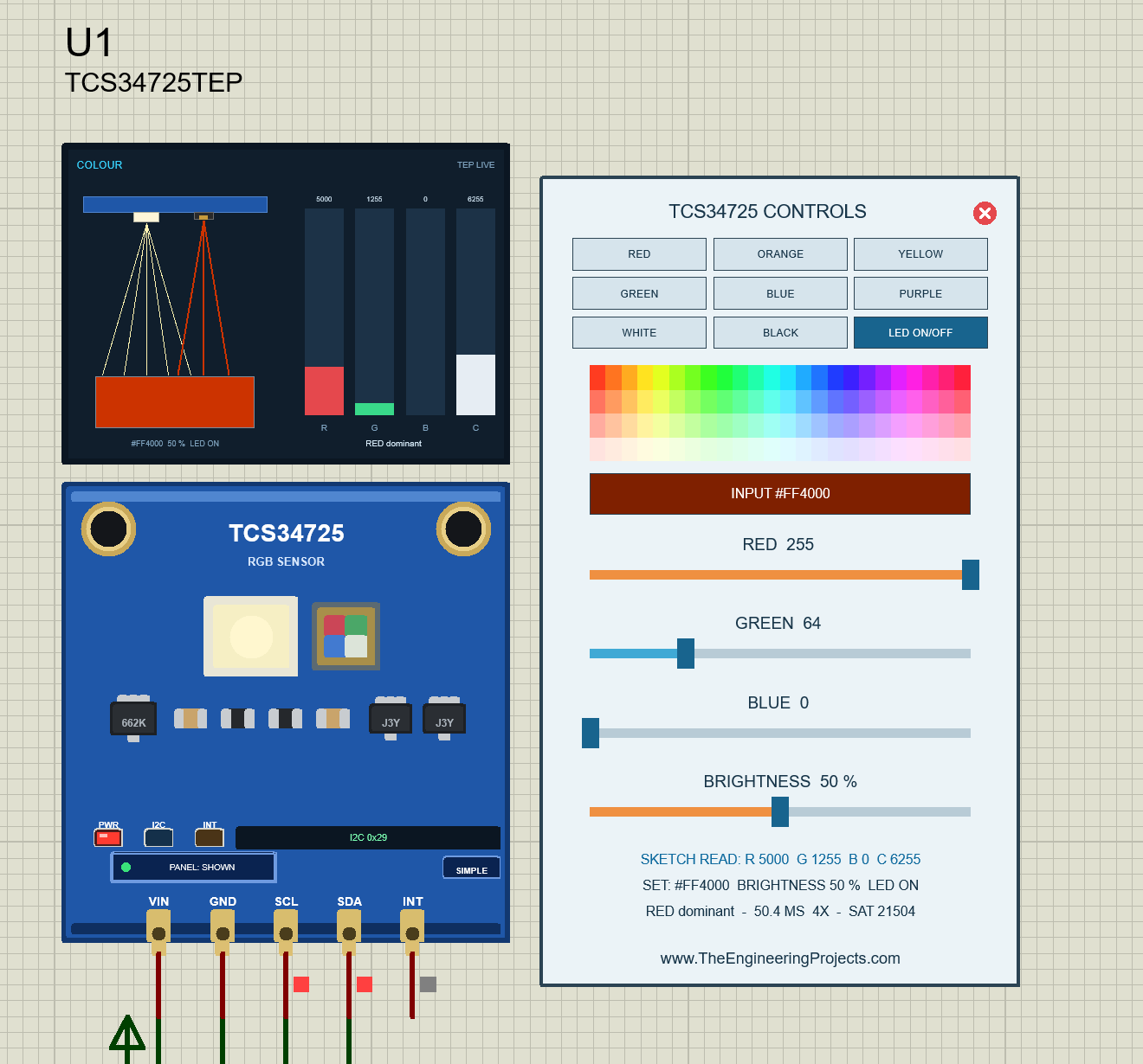
We drew the sensor as a clean TEP board in the blue of the real breakout: two gold mounting holes, the "TCS34725 RGB SENSOR" print, the big white LED with the sensor and its four colour filters beside it, the 662K regulator and the two J3Y transistors. Here is U1, the Simple device, at the start colour:
The Colour View
Above the board, the sensor is seen from the side. The white LED shines onto the object, drawn in its colour, and the light comes back to the sensor in that colour. Four bars show the red, green, blue and clear counts your sketch read, up to the saturation level, with the colour's name below, by the demo's rule. The line under the object, "#FF4000 50 % LED ON", is what you set.
Pinout
The five pins keep the v1.0 names, order and places. The real breakout has seven: LED, INT, SDA, SCL, 3V3, GND and VIN. Here, the white LED is the LED property instead of a pin.
| Pin | What it does | Demo connection |
|---|---|---|
| VIN | Power | Supply terminal |
| GND | Ground | GND |
| SCL | I2C clock | Arduino A5 |
| SDA | I2C data | Arduino A4 |
| INT | Interrupt output, active low (it also drives the INT LED) | Not connected |
LEDs and Indicators
| Indicator | What it shows |
|---|---|
| Colour view | The LED light, the object in its colour, the R / G / B / C bars and the colour's name |
| PWR LED (red) | Lit while the board has power |
| I2C LED (blue) | Flashes with every I2C transaction to this sensor |
| INT LED (amber) | Lit while the INT pin is active |
| I2C 0x29 | The live address |
| PANEL / OPEN PANEL, SIMPLE / ADVANCE | The panel button and the device badge |
The PWR, I2C and INT LEDs are a TEP addition; the big white LED is the one the real board carries.
Component Properties
| Property | Meaning | Default |
|---|---|---|
| RED, GREEN, BLUE | The object's colour, 0 to 255 | 255, 64, 0 |
| BRIGHTNESS | How strongly the object is lit, 0 to 100 % | 50 |
| LED | New in v1.1: the white LED, 1 = on (as in v1.0), 0 = off (the ambient light only) | 1 (on) |
Every Run starts again from these properties, not from the last slider positions. The panel style comes from the device (Simple or Advance), not from a property.
TCS34725 Simple: The Control Panel on the Sheet
Beside the Simple board sits the TCS34725 CONTROLS panel (on the right of the image above):
| Part | What it does |
|---|---|
| Header, red X | TCS34725 CONTROLS; the X closes the panel |
| Nine presets | RED, ORANGE, YELLOW, GREEN, BLUE, PURPLE, WHITE, BLACK and LED ON/OFF; the active ones turn dark blue |
| Palette | The v1.0 colour palette: click or drag it to pick a colour |
| INPUT | A preview of the colour you set, with its hex code |
| RED, GREEN, BLUE, BRIGHTNESS | The four v1.0 sliders |
| SKETCH READ | What your sketch really read over I2C, decoded by the model |
| SET line | The colour, the brightness and the white LED you set |
| Name line | The colour's name, and the integration time, gain and saturation (SAT) your sketch chose |
In the start image, LED ON/OFF is dark blue: the white LED is on. SKETCH READ is the line to watch: it is not what the sliders say, but what your Arduino got from the chip.
GREEN: One Channel Only
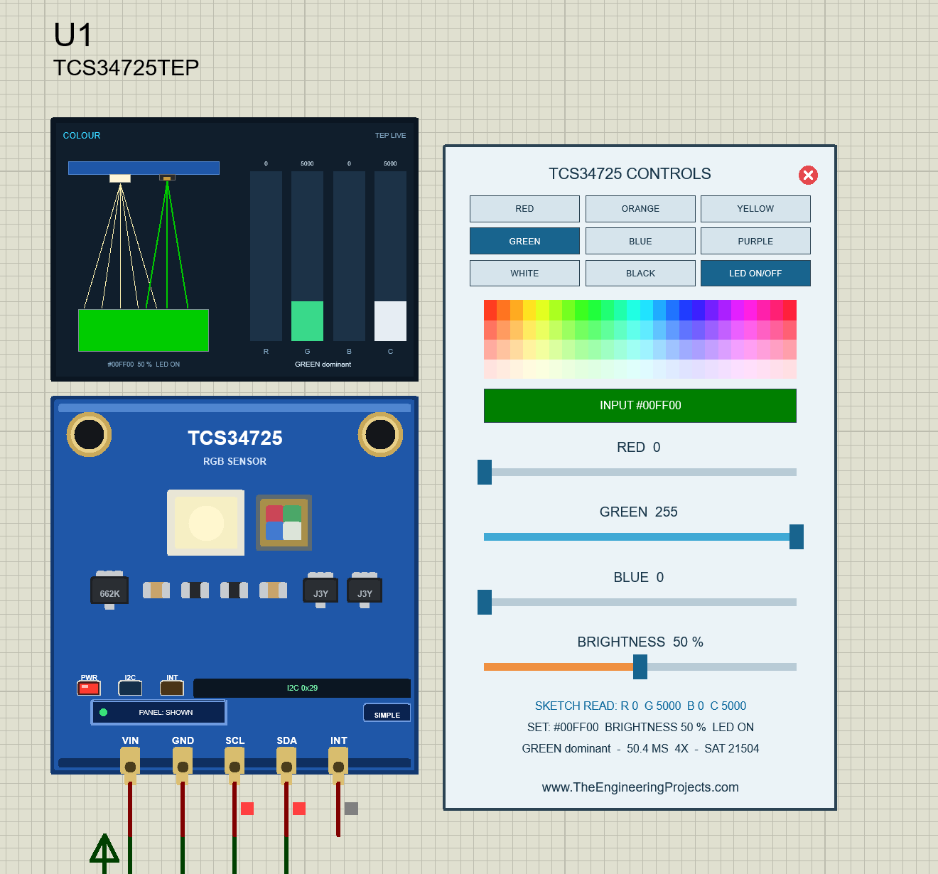
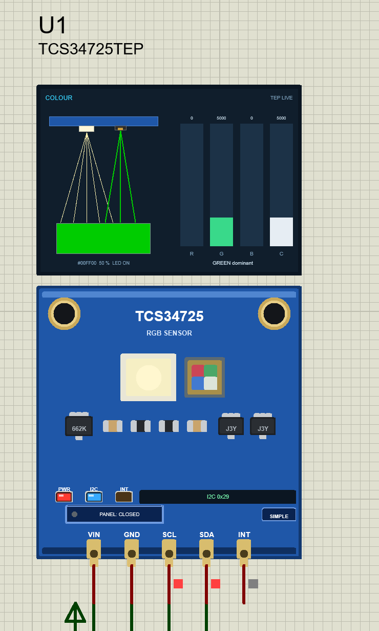
Click GREEN: the preview turns to #00FF00, the sliders jump to 0, 255 and 0, and the returning light turns green: R 0 G 5000 B 0 C 5000. Clear equals green, because green is the only light. U3 prints "R:0 G:5000 B:0 C:5000 | GREEN dominant", and the red-detector LED D1 goes off (see the full circuit below).
PURPLE: Why the Demo Says BLUE
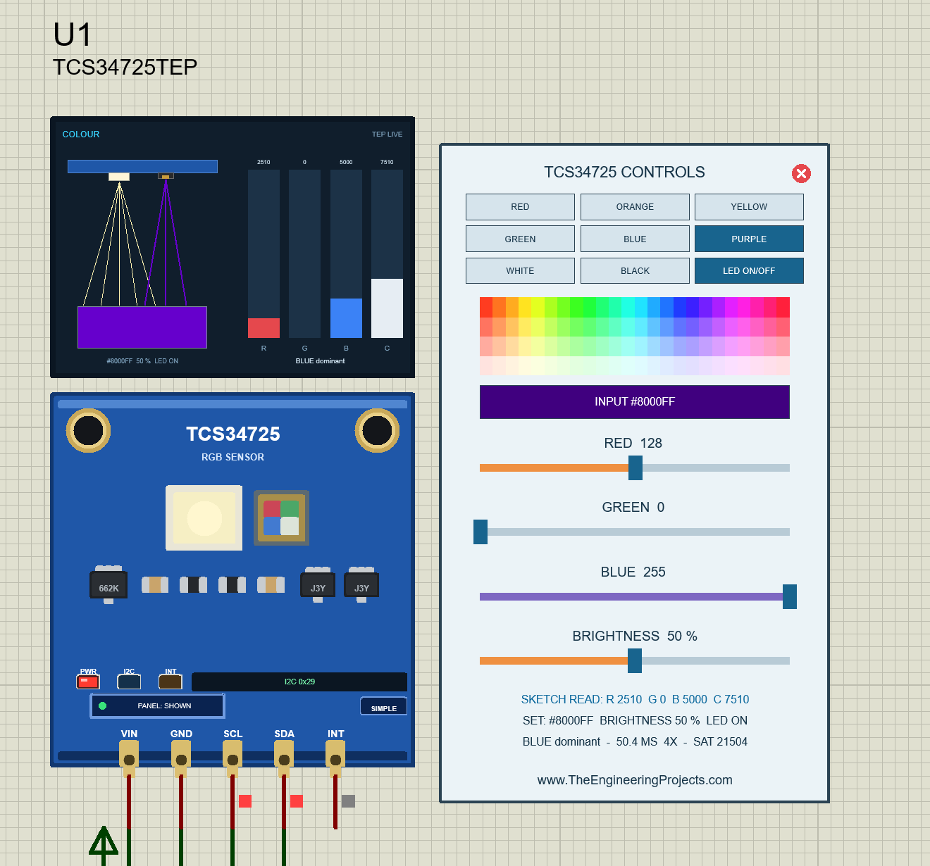
Click PURPLE: #8000FF, which is red 128, green 0 and blue 255. The counts are R 2510 (128 / 255 of 5000), G 0, B 5000 and C 7510. The demo calls a channel dominant when it is more than 1.2 times each of the others: 5000 is more than 1.2 x 2510 = 3012, so the name is "BLUE dominant". The sensor never sees "purple"; the names come from your sketch's rules, and you can add your own.
LED OFF: a Quarter of the Light
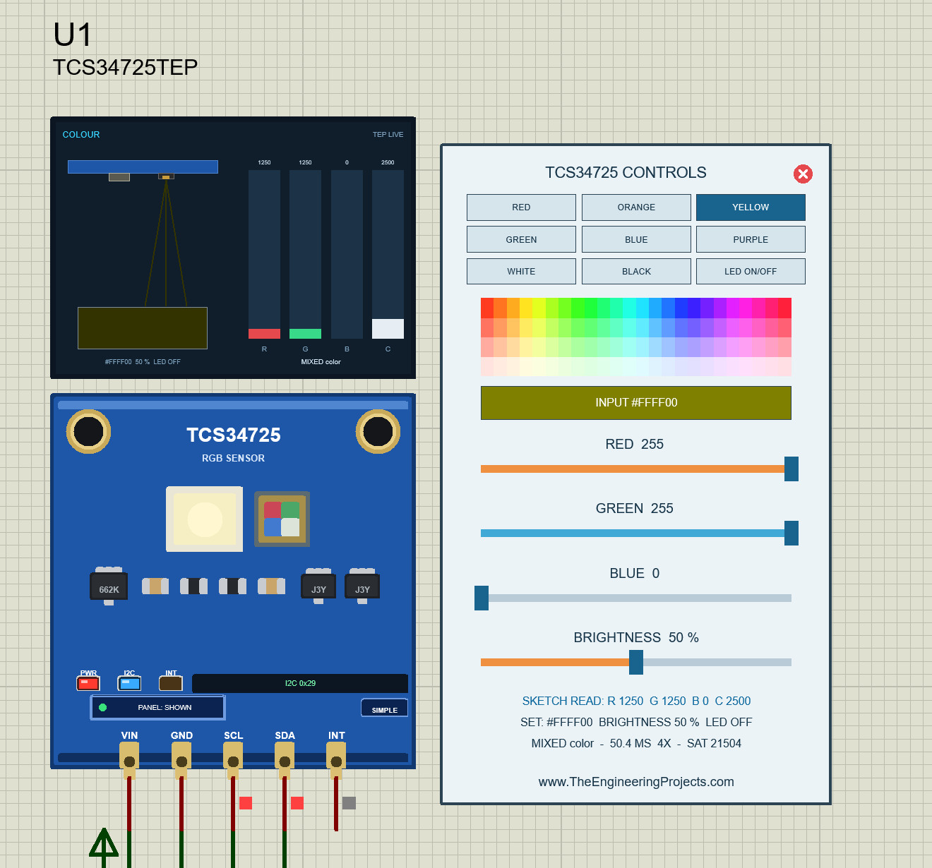
Click YELLOW (#FFFF00): with the LED on, U3 prints R:5000 G:5000 B:0 C:10000 and "MIXED color", because red and green are equal and neither is 1.2 times the other. Now click LED ON/OFF. The button turns light, the LED in the colour view goes dark, the object dims, and the SET line says LED OFF. The counts drop to 25 %: R 1250, G 1250, C 2500. The name stays "MIXED color", because the channels keep their ratio.
Closing the Panel
Click the red X: the board button says PANEL: CLOSED, and the sensor keeps running. PANEL brings the panel back. Here, U1 is at GREEN again:
TCS34725 Advance: The Pop-Up Sensor Window
The Advance device keeps only the board on the schematic. Here is U2, at the start colour:
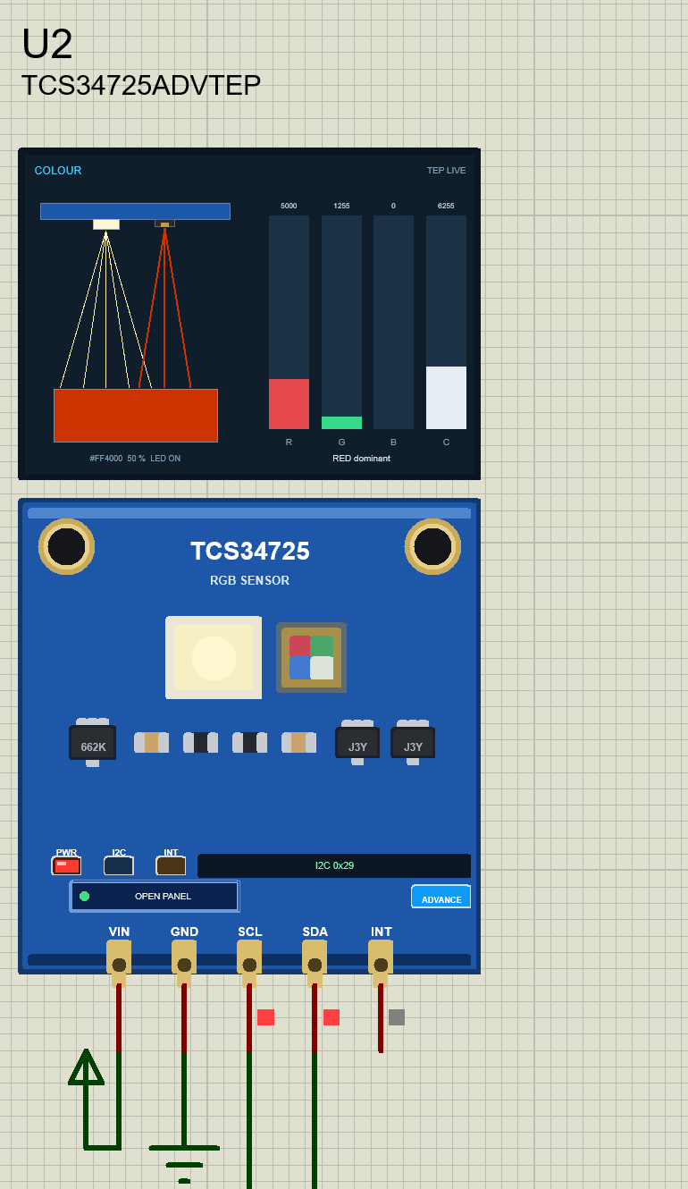
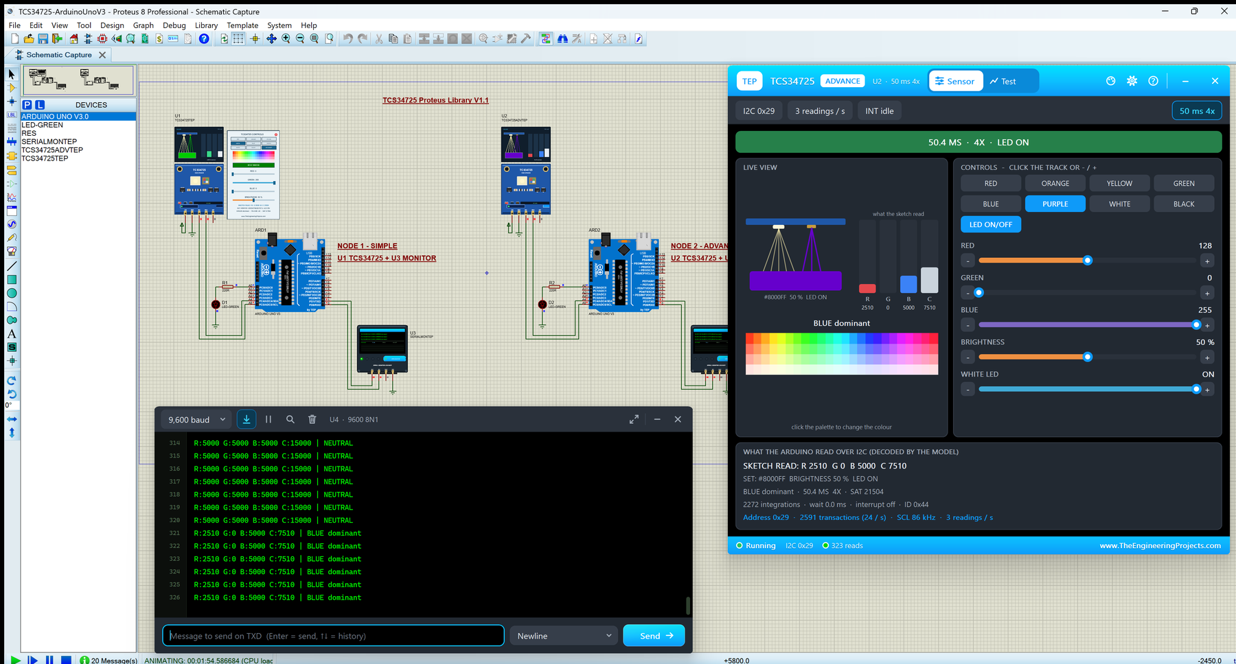
At Run, the "TEP TCS34725 Advance" pop-up opens with the look of our TEP Serial Monitor and no Windows title bar: move it by its header, resize or minimise it, and reopen it with OPEN PANEL. The header shows the state (here U2 · 50 ms 4x, the integration time, rounded, and the gain), the Sensor and Test tabs and the palette (theme), gear (Settings) and ? (Help) icons.
The Sensor Page
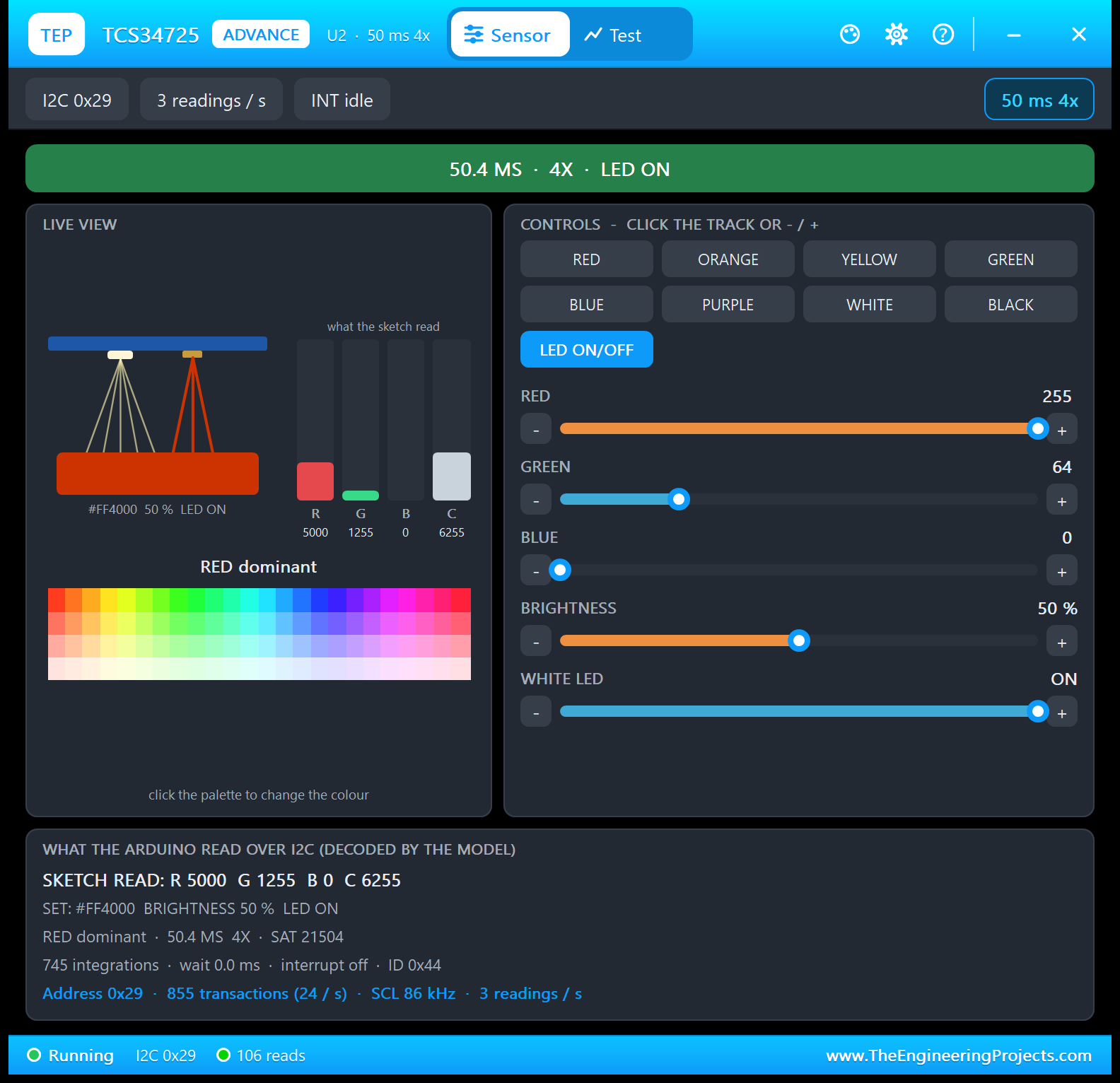
- Toolbar chips: I2C 0x29, 3 readings / s, INT idle (the INT pin is not active) and 50 ms 4x.
- Green bar: the integration time and gain your sketch set, and the white LED.
- LIVE VIEW: the large colour view with "what the sketch read" as bars, the colour's name, and a palette to click.
- CONTROLS: the eight colour presets, LED ON/OFF, and click-sliders with - / + for RED, GREEN, BLUE, BRIGHTNESS and WHITE LED, which says ON or OFF in words.
- WHAT THE ARDUINO READ OVER I2C: SKETCH READ, the SET line, the name with SAT 21504, 745 integrations, interrupt off, ID 0x44, and 855 transactions with an SCL clock of 86 kHz.
In the featured image, I clicked PURPLE on this page. The view turned purple, the bars read 2510, 0, 5000 and 7510, and U4 switched from the NEUTRAL lines of a white object (5000 on every channel) to "R:2510 G:0 B:5000 C:7510 | BLUE dominant".
The Test Page: Four Measured Sensor Test Tools
The four tools on the Test tab only change the sensor's inputs (and restore them) and watch the I2C reads your Arduino really makes; they never talk to your Arduino. So every number is what the chip and your sketch really did, timed with the simulation clock. Each tool ends with a bold "Good for:" line. All results below come from U2 with the demo sketch.
1. I2C Check: What Did Your Sketch Write Into the Chip?
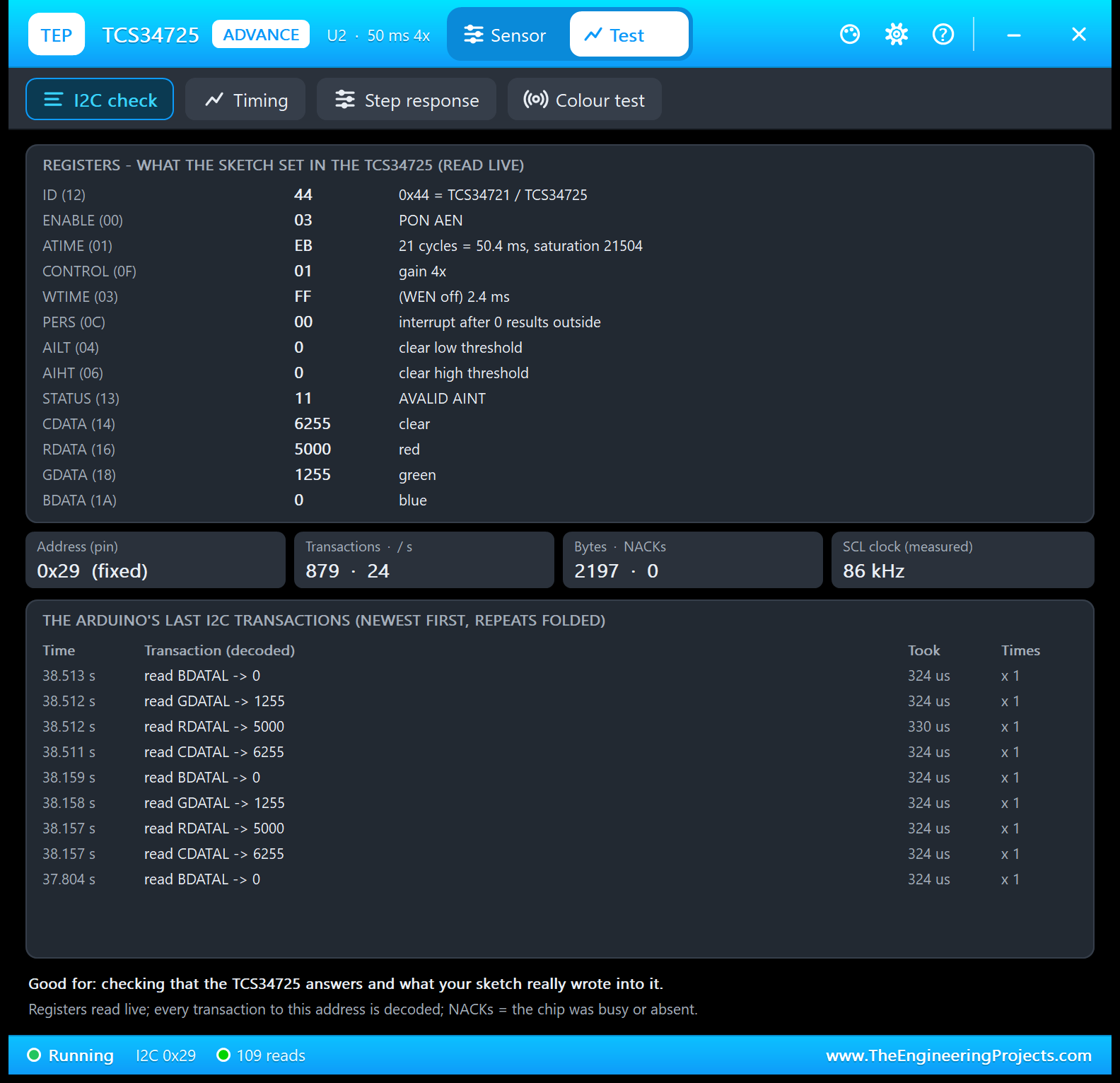
Good for: "checking that the TCS34725 answers and what your sketch really wrote into it." It works live, without a Run button. Read the register table like a checklist:
- ID 44: a TCS34725 answers ("0x44 = TCS34721 / TCS34725").
- ENABLE 03: PON (power on) and AEN (the RGBC converter running); no WEN, no AIEN.
- ATIME EB and CONTROL 01: 21 cycles = 50.4 ms, saturation 21504, gain 4x.
- WTIME FF: 2.4 ms, but WEN is off, so there is no pause between results.
- STATUS 11: AVALID (a valid result) and AINT. With PERS, AILT and AIHT all 0, every clear count is outside the thresholds, but without AIEN the INT pin stays idle.
- CDATA 6255, RDATA 5000, GDATA 1255, BDATA 0: the four channels.
Below the table: the address 0x29 (fixed), 879 transactions, 2197 bytes with 0 NACKs, and the SCL clock, measured on the pin: 86 kHz. The newest transactions show two demo readings: getRawData() reads CDATAL (6255), RDATAL (5000), GDATAL (1255) and BDATAL (0), about 324 us each, and the next reading starts 354 ms later. Reading a low byte latches its high byte, so both halves belong to the same result.
2. Timing: How Often Is There New Data?
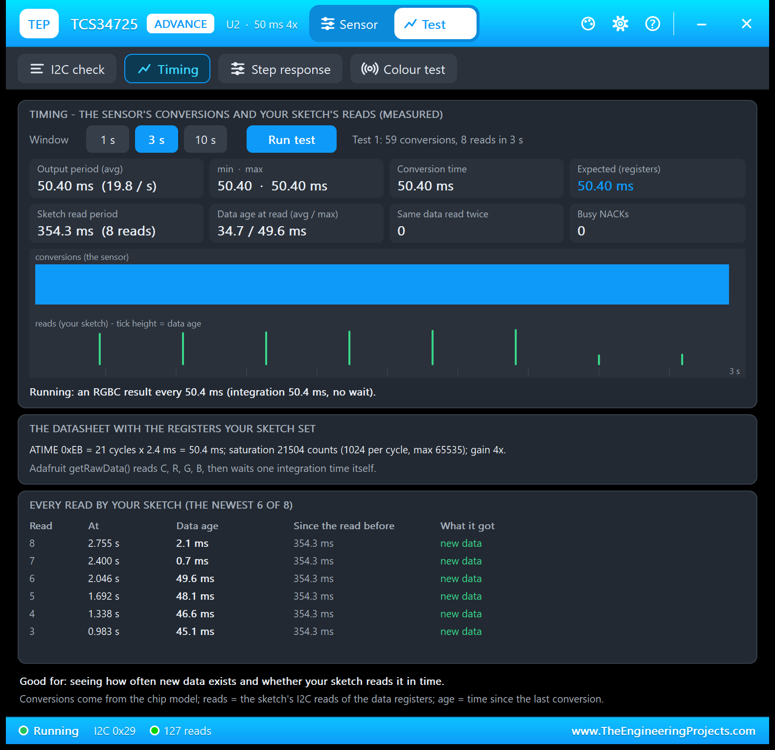
Good for: "seeing how often new data exists and whether your sketch reads it in time." Choose a 1, 3 or 10 s window and click Run test. In 3 s, the sensor made 59 conversions of 50.40 ms, back to back (19.8 per second), exactly as the registers expect: "an RGBC result every 50.4 ms (integration 50.4 ms, no wait)". The sketch read 8 times, every 354.3 ms, never the same result twice, with no busy NACKs.
The middle box explains the 354.3 ms: Adafruit getRawData() "reads C, R, G, B, then waits one integration time itself" (51 ms), and the demo adds its delay(300). In the list, the data age climbs by 1.5 ms per read: 45.1, 46.6, 48.1, 49.6, then 0.7 and 2.1 ms. Seven integrations take 352.8 ms, the sketch waits 354.3 ms, so each read comes 1.5 ms later in the cycle. The demo sees one result in seven.
3. Step Response: How Quickly Does a Change Reach Your Sketch?
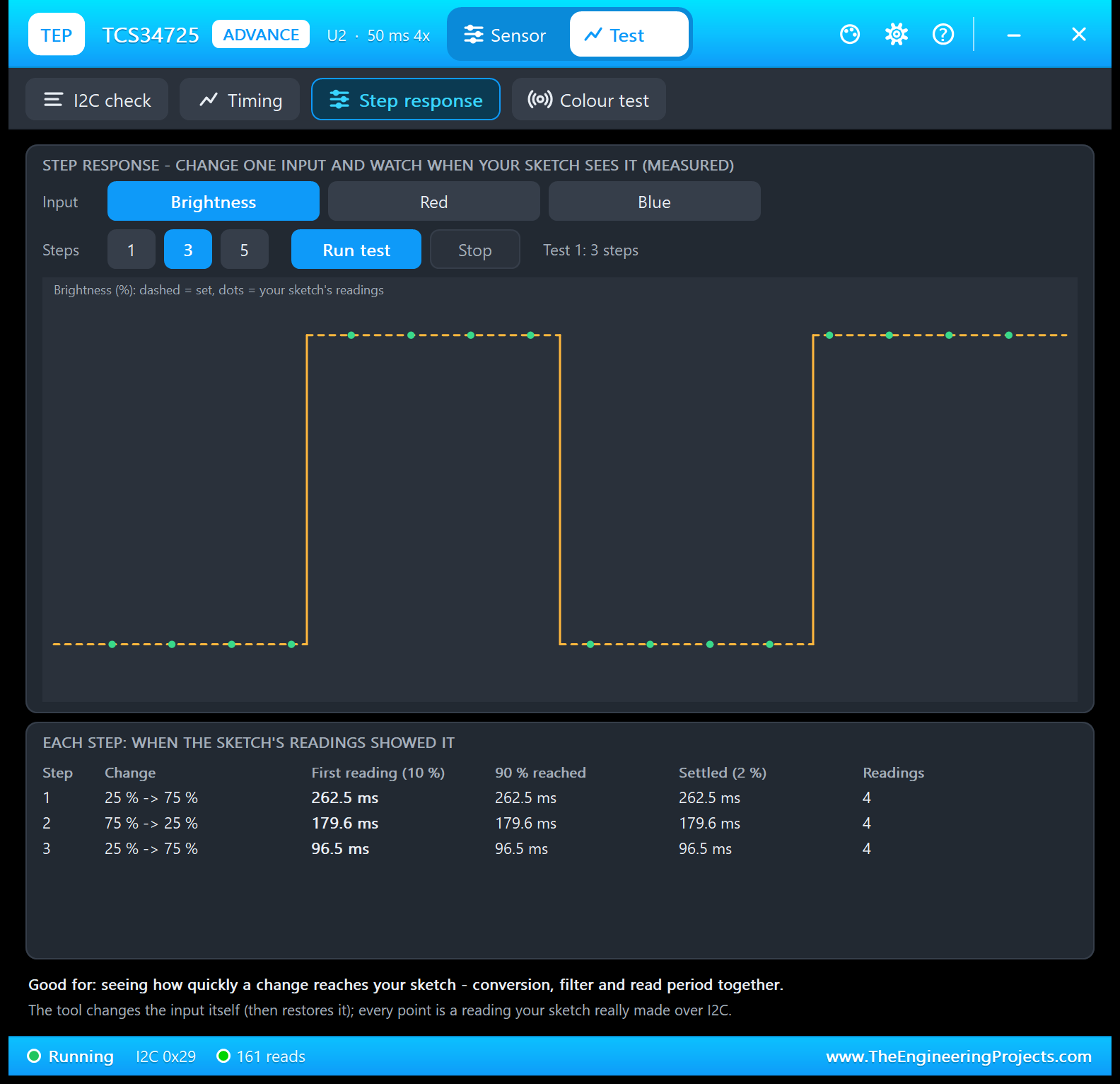
Good for: "seeing how quickly a change reaches your sketch - conversion, filter and read period together." Choose Brightness (25 to 75 %), Red (255 to 0) or Blue (0 to 255), and 1, 3 or 5 steps of 1.5 s. The tool steps the input, restores it afterwards, and plots the set value (dashed) and the value your sketch's counts stand for (dots).
| Step | Change | First reading (10 %) | 90 % reached | Settled (2 %) | Readings |
|---|---|---|---|---|---|
| 1 | 25 to 75 % | 262.5 ms | 262.5 ms | 262.5 ms | 4 |
| 2 | 75 to 25 % | 179.6 ms | 179.6 ms | 179.6 ms | 4 |
| 3 | 25 to 75 % | 96.5 ms | 96.5 ms | 96.5 ms | 4 |
The first reading after each step already had the whole change, so the time is the wait for the sketch's next read. It falls by about 83 ms per step, because four reads take 4 x 354.3 = 1417.2 ms, 82.8 ms less than a 1.5 s step. Want faster answers? Shorten the delay(300).
4. Colour Test: Does Your Sketch Name the Colours Right?
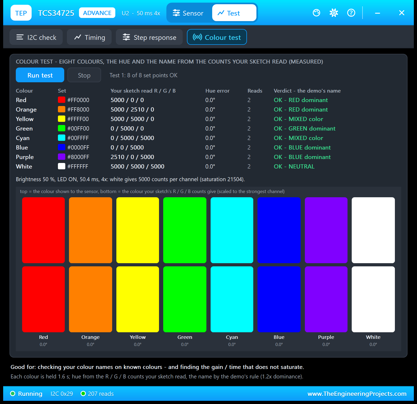
Good for: "checking your colour names on known colours - and finding the gain / time that does not saturate." Click Run test: the tool shows eight colours to the sensor, 1.6 s each, computes the hue from the R / G / B counts your sketch read, and names the colour by the demo's rule (1.2x dominance):
| Colour | Set | Your sketch read R / G / B | Hue error | The demo's name |
|---|---|---|---|---|
| Red | #FF0000 | 5000 / 0 / 0 | 0.0° | RED dominant |
| Orange | #FF8000 | 5000 / 2510 / 0 | 0.0° | RED dominant |
| Yellow | #FFFF00 | 5000 / 5000 / 0 | 0.0° | MIXED color |
| Green | #00FF00 | 0 / 5000 / 0 | 0.0° | GREEN dominant |
| Cyan | #00FFFF | 0 / 5000 / 5000 | 0.0° | MIXED color |
| Blue | #0000FF | 0 / 0 / 5000 | 0.0° | BLUE dominant |
| Purple | #8000FF | 2510 / 0 / 5000 | 0.0° | BLUE dominant |
| White | #FFFFFF | 5000 / 5000 / 5000 | 0.0° | NEUTRAL |
Every hue matches, because the model is exact, and 8 of 8 set points OK means the demo gave each colour the name its rule expects: orange counts as RED dominant, yellow and cyan as MIXED color, purple as BLUE dominant. The tiles compare the colour shown to the sensor (top) with the colour your sketch's counts give (bottom). White gives 5000 counts per channel against a saturation of 21504; type GAIN 16 on U4 and run it again, and the bright colours come out SATURATED.
Settings and Help
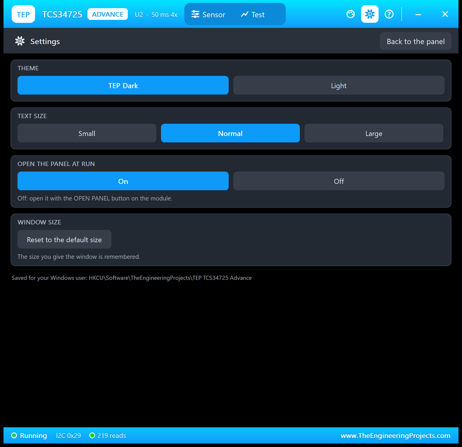
The gear opens Settings: theme (TEP Dark or Light), text size, open the panel at Run, and the window size, saved for your Windows user.
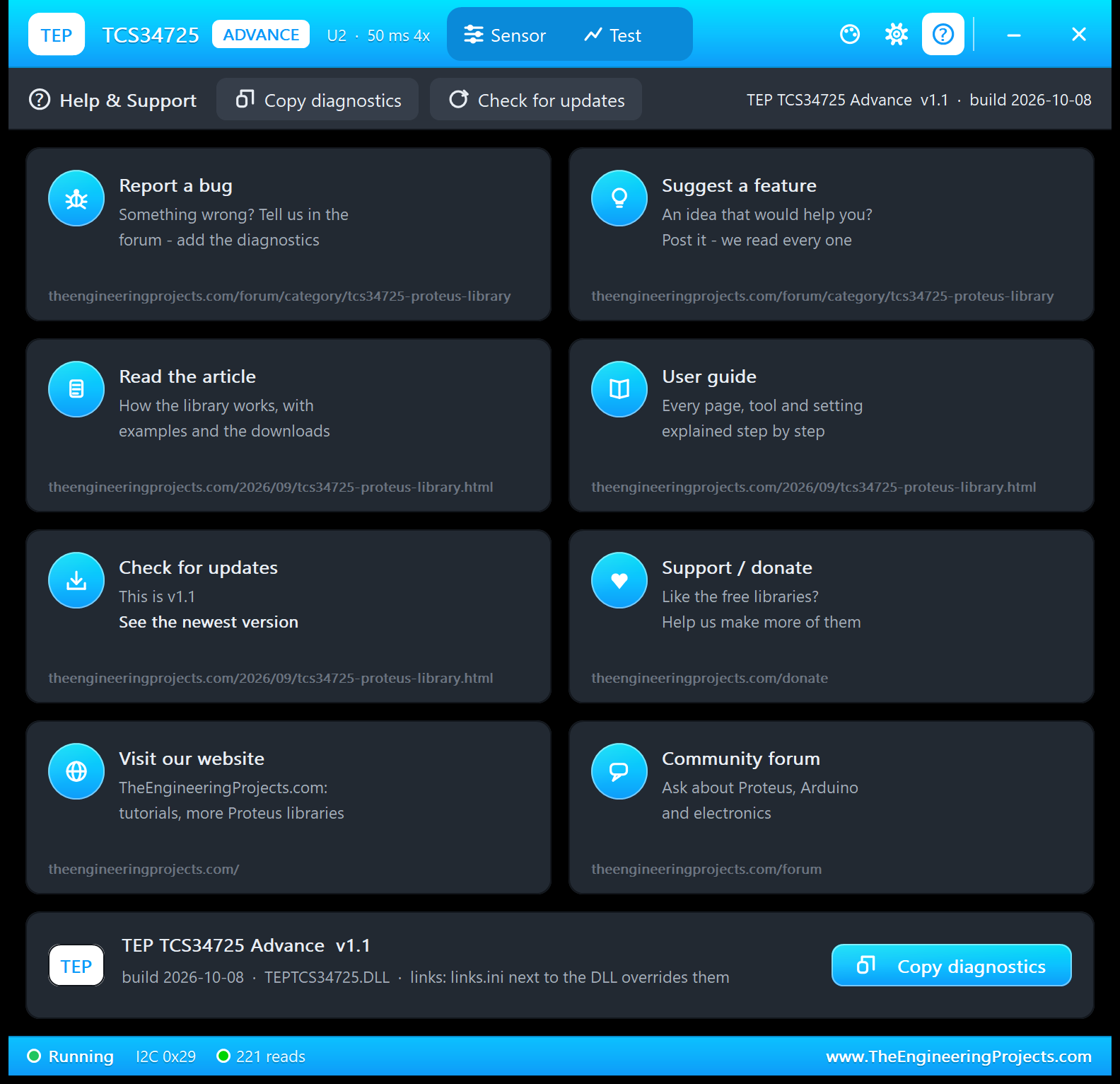
The ? icon opens Help & Support: eight cards with their links (the TCS34725 forum board for bugs and ideas, this article, updates, donate, website, forum), Check for updates, and Copy diagnostics for a bug report: the inputs, what was read, the registers, the last transactions and the test results. A links.ini next to the DLL can change the links.
TCS34725 Red Detector with Arduino in Proteus
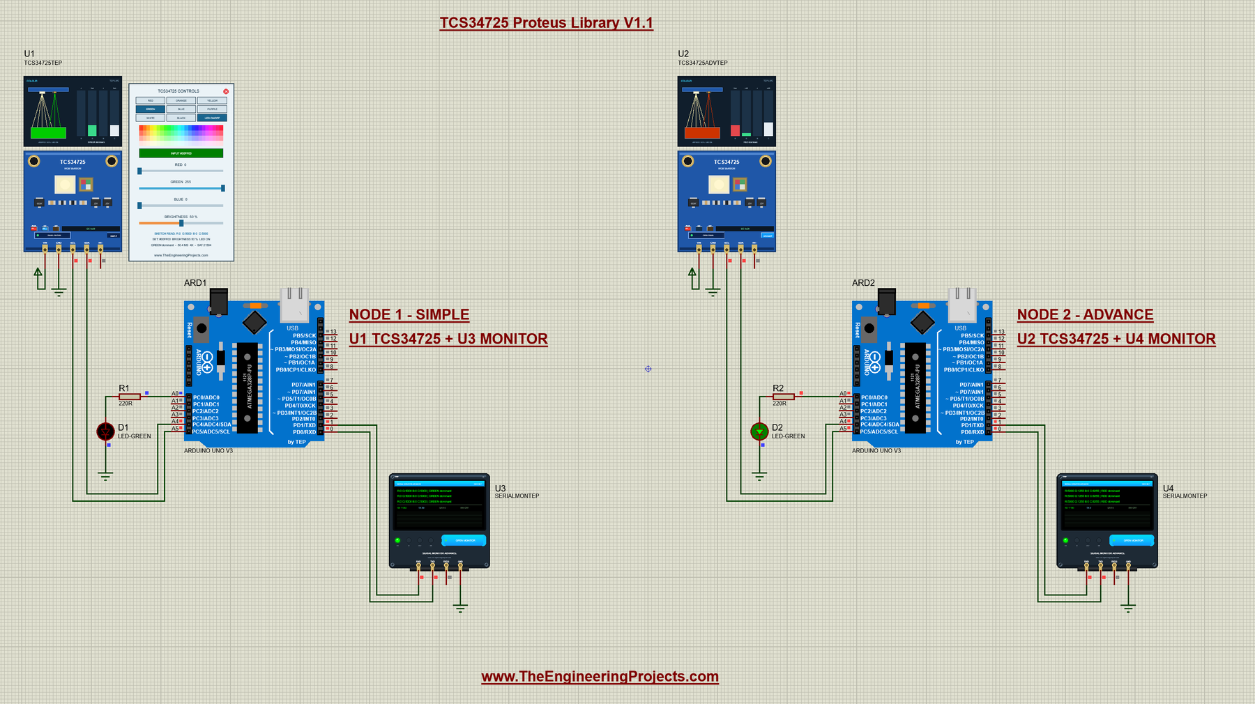
Open TCS34725-ArduinoUnoV3.pdsprj from the Proteus Simulation folder, with TCS34725_Demo.hex and both DLLs beside it. Its two Arduino UNOs from our Arduino Library for Proteus V3.0 run the same HEX file:
- NODE 1 - SIMPLE: UNO 1 (ARD1) with the TCS34725 Simple (U1), the red-detector LED D1 on A0 and Serial Monitor U3.
- NODE 2 - ADVANCE: UNO 2 (ARD2) with the TCS34725 Advance (U2), the red-detector LED D2 on A0 and Serial Monitor U4.
Both sensors sit at 0x29; each UNO has its own I2C bus, so that is no conflict.
Wiring
| From | To | Why |
|---|---|---|
| TCS34725 VIN / GND | Supply / ground | Power (the PWR LED lights) |
| TCS34725 SCL / SDA | Arduino A5 / A4 | I2C clock and data |
| TCS34725 INT | Not connected | Optional: active low, it drives the INT LED and can go to D2 for attachInterrupt |
| LED + 220 Ω | A0 to GND | The red detector |
| Serial Monitor RXD / TXD / GND | Arduino D1 / D0 / ground | Shows what the Arduino prints, sends what you type |
| Serial Monitor RXD2 | Not connected | I2C has no serial line to watch |
A4 and A5 are the UNO's I2C pins (see our Introduction to Arduino UNO). The Wire library turns on the UNO's internal pull-ups, so the simulation needs no external pull-up resistors; a real breakout has its own on board.
The Arduino Code
The sketch uses the unmodified Adafruit TCS34725 library 1.4.4, like v1.0, with the v1.0 settings of 50.4 ms and 4x:
#include <Wire.h>
#include <Adafruit_TCS34725.h>

Adafruit_TCS34725 sensor(TCS34725_INTEGRATIONTIME_50MS,TCS34725_GAIN_4X);
bool ready=false;
The new v1.1 variables: the LED pin, the integration time and gain the sketch keeps track of, and two flags:
const uint8_t LED_PIN=A0;
uint8_t atime=0xEB, gainCode=1;    // 21 cycles x 2.4 ms = 50.4 ms, 4x
bool hexOn=false, redOn=false;
In setup(), the I2C bus gets a 25 ms timeout, and begin() checks the chip and starts it. If it fails, the sketch says what to check. Then come the two v1.0 lines and the new v1.1 line:
  Serial.begin(9600); Wire.begin(); Wire.setWireTimeout(25000,true);
  pinMode(LED_PIN,OUTPUT); digitalWrite(LED_PIN,LOW);
  ready=sensor.begin();
  if(!ready) { Serial.println(F("TCS34725 not found. Check VIN, GND, A4/SDA and A5/SCL.")); return; }
  Serial.println(F("TEP TCS34725 - click the color palette or drag RGB / brightness."));
  Serial.println(F("50.4 ms integration, 4x gain. RGBC values are raw ADC counts."));
  Serial.println(F("TEP TCS34725 Demo v1.1 - type HELP in the Serial Monitor"));
The loop reads the four counts and prints them, as in v1.0. Remember: getRawData() waits one integration time after reading.
  uint16_t r,g,b,c;
  sensor.getRawData(&r,&g,&b,&c);
  Serial.print(F("R:")); Serial.print(r);
  Serial.print(F(" G:")); Serial.print(g);
  Serial.print(F(" B:")); Serial.print(b);
  Serial.print(F(" C:")); Serial.print(c);
  Serial.print(F(" | "));
The v1.0 sketch had the number 21504 written into its SATURATED test, which only fits 50.4 ms. In v1.1, the saturation level follows the integration time:
uint16_t saturation() { const uint32_t s=(uint32_t)(256-atime)*1024; return s>65535 ? 65535 : s; }Then the v1.0 rules name the colour, in this order: DARK, SATURATED, NEUTRAL (all channels within 12 %), one channel dominant (1.2 times each of the others), or MIXED. New: red=true marks "RED dominant" for the LED.
  bool red=false;
  if(c==0) Serial.println(F("DARK"));
  else if(c>=saturation()) Serial.println(F("SATURATED - reduce brightness or gain"));
  else {
    uint16_t hi=max(r,max(g,b)),lo=min(r,min(g,b));
    if((uint32_t)(hi-lo)*100 < (uint32_t)hi*12) Serial.println(F("NEUTRAL"));
    else if(r>g*1.2f && r>b*1.2f) { Serial.println(F("RED dominant")); red=true; }
    else if(g>r*1.2f && g>b*1.2f) Serial.println(F("GREEN dominant"));
    else if(b>r*1.2f && b>g*1.2f) Serial.println(F("BLUE dominant"));
    else Serial.println(F("MIXED color"));
  }
So a saturated red does not light the LED: it needs a valid "RED dominant" reading. After HEX ON, the sketch adds the colour as #RRGGBB, each channel scaled to the strongest one, so the brightness and the gain do not change it as long as nothing clips. Then the red-detector LED follows, and the loop waits:
  if(hexOn && c) {                 // the colour itself: each channel scaled to the strongest one
    const uint16_t hi=max(r,max(g,b));
    Serial.print(F("Hex: #")); printHex(hi ? (uint32_t)r*255/hi : 0); printHex(hi ? (uint32_t)g*255/hi : 0); printHex(hi ? (uint32_t)b*255/hi : 0); Serial.println();
  }
  if(red!=redOn) { redOn=red; digitalWrite(LED_PIN,redOn ? HIGH : LOW); }
  delay(300);
GAIN accepts only the four gains of the chip and sets one with the library:
  else if(!strcmp(s,"GAIN")) {
    const int g=arg ? atoi(arg) : 0; int code=-1;
    for(uint8_t i=0;i<4;++i) if(g==GAINS[i]) code=i;
    if(code<0) { Serial.println(F("GAIN 1, 4, 16 or 60")); return; }
    gainCode=code; sensor.setGain((tcs34725Gain_t)gainCode);
    Serial.print(F("Gain: ")); Serial.print(GAINS[gainCode]); Serial.println(F("x"));
TIME rounds your milliseconds to whole 2.4 ms cycles, writes ATIME and prints the new saturation:
    int cycles=(int)(ms/2.4+0.5); if(cycles<1) cycles=1; if(cycles>256) cycles=256;
    atime=(uint8_t)(256-cycles); sensor.setIntegrationTime(atime);
    Serial.print(F("Integration time: ")); Serial.print(cycles*2.4,1); Serial.print(F(" ms (ATIME 0x")); Serial.print(atime,HEX);
    Serial.print(F("), saturation ")); Serial.println(saturation());
HELP prints one line, short enough for the Serial Monitor's Simple interface:
void help() {
  Serial.println(F("Commands: HELP, STATUS, GAIN 1|4|16|60, TIME ms (2.4 .. 614), HEX ON|OFF"));
}
The settings live in the chip and in RAM, so a new Run brings back the start values. To change the sketch, export a new HEX file and load it into both UNOs; see How to get the HEX file from Arduino. New to Arduino? Start with our Arduino Tutorial for Beginners.
Serial Monitor Commands
| Command | What it does |
|---|---|
| HELP | The command list (one line) |
| STATUS | Two lines: the integration time with ATIME and the gain; the saturation and the HEX setting |
| GAIN 1|4|16|60 | The analog gain (start: 4x) |
| TIME ms | The integration time, 2.4 to 614 ms in 2.4 ms steps (start: 50.4 ms) |
| HEX ON | OFF | Also print the colour as #RRGGBB, scaled to the strongest channel |
How to Run the Demo
- Press Run. Both Serial Monitors (9600 baud) and U2's pop-up open, and D1 and D2 light: the start colour is "RED dominant".
- On U1's panel, click GREEN (D1 goes off), PURPLE, YELLOW and LED ON/OFF; then try the palette and BRIGHTNESS.
- Click RED on U1, then STATUS on U3; type HEX ON, then click GAIN 16 and TIME 154. Type GAIN 4 and TIME 50 to go back.
- On U2, try the Sensor page, then the four tools on the Test tab.
- Close U2's window and open it again with OPEN PANEL; close U1's panel with its red X and open it with PANEL.
TCS34725 Proteus Simulation Results
The Serial Monitor in Its Simple Interface
Both monitors in this demo run in the Simple interface of our TEP Serial Monitor, as in every monitor screenshot here. Only the log, the send box and one slim toolbar row stay visible (baud rate, follow, pause, search and clear), so the window stays small.
- Switch to it: right-click the log and choose Simple interface, or press Ctrl+Shift+U.
- Back to the full view: click the corner button (the expand arrows at the top right), press Esc or Ctrl+Shift+U, or right-click and choose Full interface.
- Your choice is remembered.
Type commands such as STATUS or GAIN 16 in the send box and press Enter; the quick buttons (STATUS, GAIN 16, TIME 154, HELP) come back with the full view. Every line of the v1.1 sketch is 80 characters or less, so it fits this small window. Read all about the monitor in TEP Serial Monitor Advance for Proteus.
Start-Up
After Run, U3 prints the two v1.0 lines, the new v1.1 line and then a reading about three times a second:
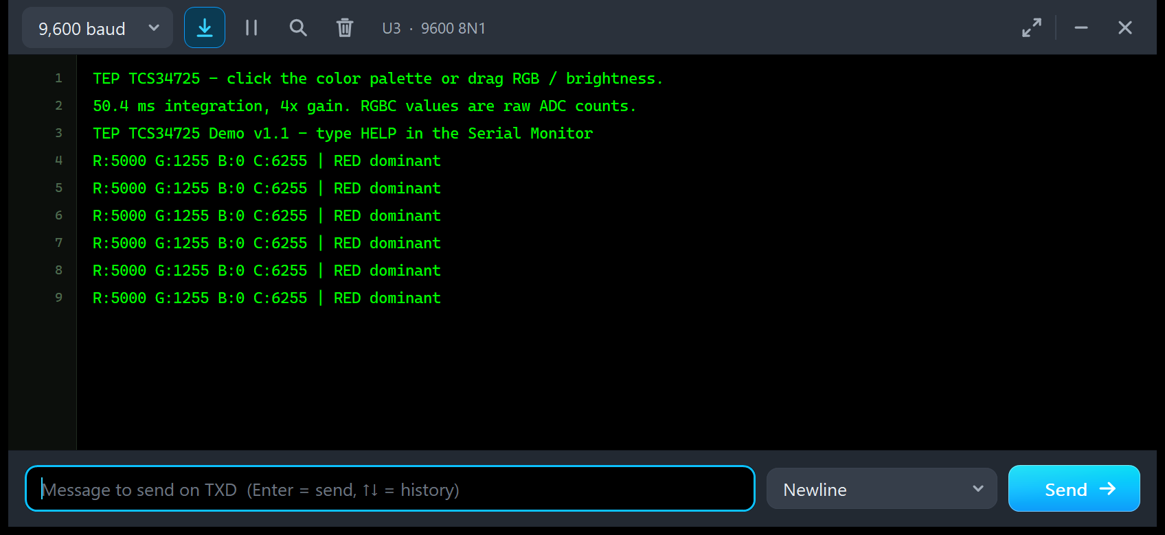
TEP TCS34725 - click the color palette or drag RGB / brightness.
50.4 ms integration, 4x gain. RGBC values are raw ADC counts.
TEP TCS34725 Demo v1.1 - type HELP in the Serial Monitor
R:5000 G:1255 B:0 C:6255 | RED dominant
R:5000 G:1255 B:0 C:6255 | RED dominant
R:5000 G:1255 B:0 C:6255 | RED dominant
These are exactly the v1.0 numbers: with the white LED on, v1.1 reads what v1.0 read.
Purple, Yellow and the White LED
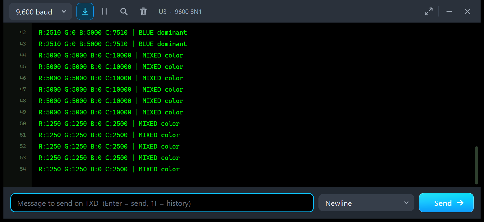
R:2510 G:0 B:5000 C:7510 | BLUE dominant
R:5000 G:5000 B:0 C:10000 | MIXED color
R:5000 G:5000 B:0 C:10000 | MIXED color
R:5000 G:5000 B:0 C:10000 | MIXED color
R:5000 G:5000 B:0 C:10000 | MIXED color
R:5000 G:5000 B:0 C:10000 | MIXED color
R:5000 G:5000 B:0 C:10000 | MIXED color
R:1250 G:1250 B:0 C:2500 | MIXED color
R:1250 G:1250 B:0 C:2500 | MIXED color
Three clicks on U1's panel: PURPLE gives "BLUE dominant", YELLOW gives "MIXED color", and LED ON/OFF drops yellow to 1250 / 1250 / 0, still "MIXED color". Each click shows in the next line.
STATUS and HEX ON
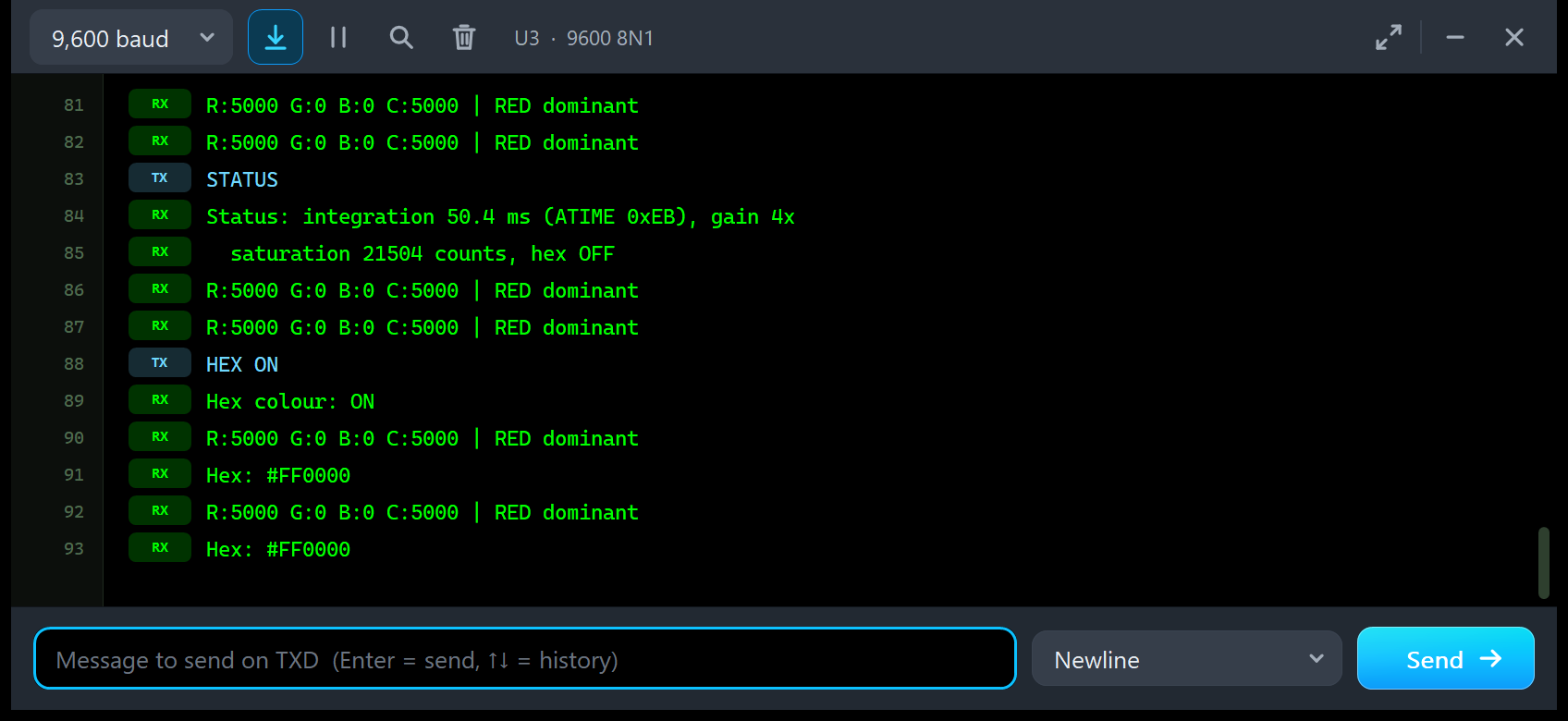
R:5000 G:0 B:0 C:5000 | RED dominant
STATUS
Status: integration 50.4 ms (ATIME 0xEB), gain 4x
  saturation 21504 counts, hex OFF
R:5000 G:0 B:0 C:5000 | RED dominant
R:5000 G:0 B:0 C:5000 | RED dominant
HEX ON
Hex colour: ON
R:5000 G:0 B:0 C:5000 | RED dominant
Hex: #FF0000
Here, U1 is at RED (#FF0000). Once you send a command, the log marks your lines TX and the sketch's lines RX. STATUS gives the integration time with its ATIME and the gain, then the saturation and the HEX setting. After HEX ON, every reading is followed by "Hex: #FF0000": red, the strongest channel, scales to FF.
GAIN 16 and TIME 154
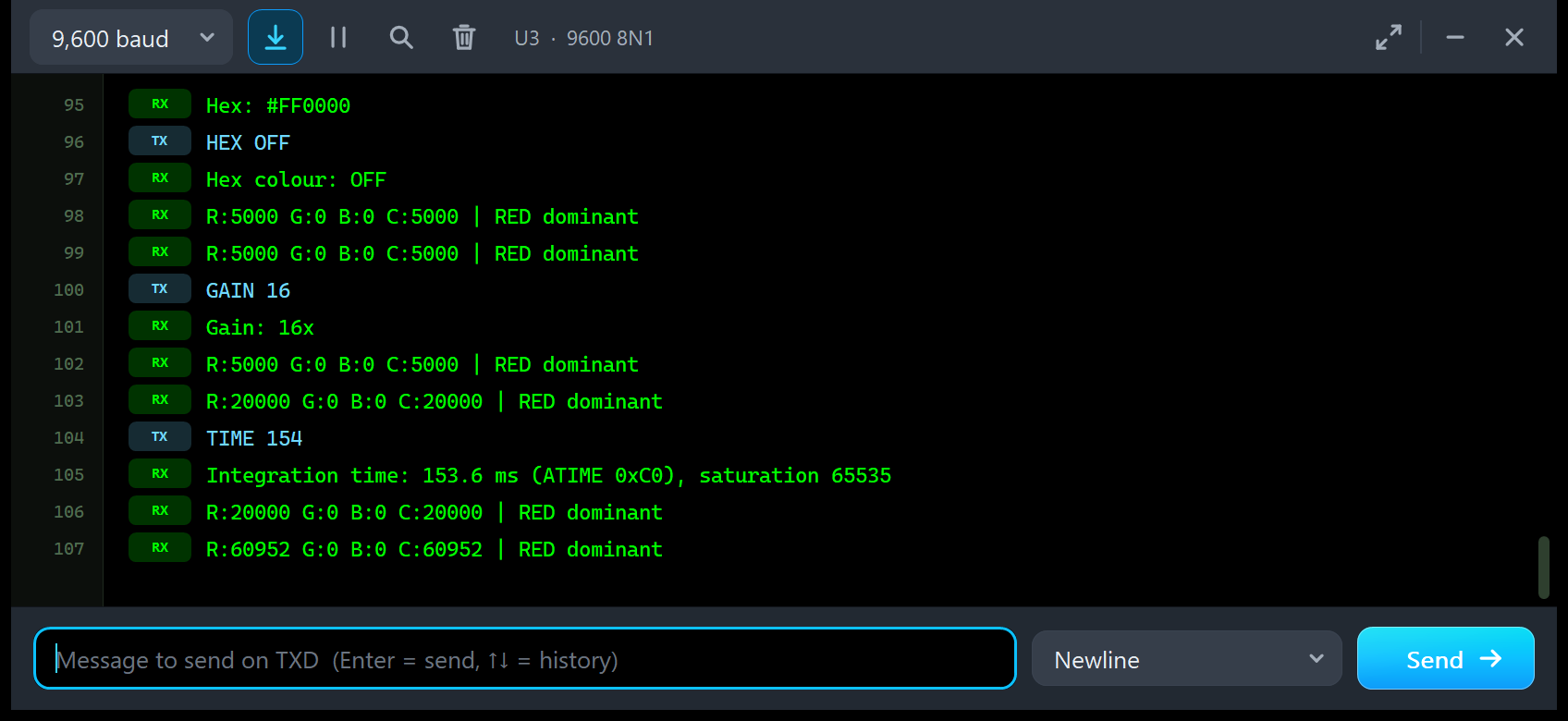
HEX OFF
Hex colour: OFF
R:5000 G:0 B:0 C:5000 | RED dominant
R:5000 G:0 B:0 C:5000 | RED dominant
GAIN 16
Gain: 16x
R:5000 G:0 B:0 C:5000 | RED dominant
R:20000 G:0 B:0 C:20000 | RED dominant
TIME 154
Integration time: 153.6 ms (ATIME 0xC0), saturation 65535
R:20000 G:0 B:0 C:20000 | RED dominant
R:60952 G:0 B:0 C:60952 | RED dominant
GAIN 16 is four times 4x: R:20000. That is still below 21504, so pure red does not saturate. At the start colour #FF4000, green adds 5020 to the clear channel, and 25020 is over the limit; the README shows that case: "R:20000 G:5020 B:0 C:21504 | SATURATED - reduce brightness or gain".
TIME 154 gives 64 cycles, 153.6 ms (ATIME 0xC0), and the saturation rises to 65535. 64 / 21 times the counts: 20000 x 64 / 21 = 60952. Look at the first line after each command: it still shows the old counts, because the sketch reads the result that was ready when it changed the setting. The next line has the new value.
Troubleshooting
- "TCS34725 not found. Check VIN, GND, A4/SDA and A5/SCL.": check VIN / GND (the PWR LED must be lit and the board must show I2C 0x29), SDA on A4 and SCL on A5; then restart the simulation.
- "SATURATED - reduce brightness or gain": the clear channel reached the saturation. Lower the gain, shorten the integration time or reduce BRIGHTNESS.
- Everything reads "DARK": BRIGHTNESS is 0, or the object is black.
- The counts are a quarter of what you expect: the LED property is 0; click LED ON/OFF.
- The readings come slowly: the Adafruit library waits one integration time after every
getRawData(), so a long TIME slows the loop down. - The part is not simulated, no panel or no monitor window: TEPTCS34725.DLL or TEPSERIALMON.DLL is missing from MODELS and the project folder; click OPEN MONITOR on a closed monitor.
- The Advance pop-up does not appear: click OPEN PANEL on the board, or turn "Open the panel at Run" back on in Settings.
- No red X, or the board looks like v1.0: the design still holds the v1.0 symbol; replace TEPTCS34725.LIB, delete TEPTCS34725.IDX and re-pick the part.
- Your own sketch uses SoftwareSerial to receive: Proteus 8.5 cannot receive with SoftwareSerial; use the hardware Serial, as the demo does, or AltSoftSerial.
Things to Know Before Using a Real TCS34725 Breakout
The demo sketch uses only Wire and the Adafruit libraries, so it runs on a real UNO and TCS34725 breakout, too. Keep in mind:
- Supply: the TCS34725 chip itself is a 3.3 V part (2.7 to 3.6 V). The breakout has a 3.3 V regulator (662K) and level shifting, so feed VIN with 3.3 V or 5 V; another board may not: check yours.
- Pull-ups: the board has its own I2C pull-ups, so A4 / A5 need nothing else.
- Address: 0x29, fixed. Two TCS34725 need separate buses, for example through an I2C multiplexer.
- The white LED: leave its LED pin open and the LED is on; tie it to GND to switch it off, or to INT so that
setInterrupt(true)switches it off (Adafruit's trick). - Infrared: the chip has an infrared-blocking filter; the model does not simulate infrared.
- Real counts depend on the light, the distance (a few mm) and the surface. Calibrate with a white and a black card, and shield the sensor from the room light. The model gives exact, noise-free counts.
- Lux and colour temperature: the Adafruit helpers give no calibrated values on our ideal counts.
Limitations of the Simulation
- Not modelled: the spectral responses of the filters (red, green and blue are the object's colour directly), infrared, noise, the temperature drift, the real lux and colour-temperature relation, and the LED pin (a property instead). The clear channel is the sum of the colour channels.
- The model is our own implementation, written from the TCS34725 data sheet (registers, timing, interrupt); it contains no ams code. The light-to-counts relation and the LED-off light are model values.
- Licences: BSD for the Adafruit TCS34725 library 1.4.4, MIT for Adafruit BusIO 1.17.4. The HEX file also contains the Arduino AVR core 1.8.6, which includes LGPL-licensed code; its source code is on GitHub.
- Tested in Proteus 8.5 on 8 Oct 2026 (the demo, both panels, the four tools, a v1.0 design and every screenshot here) and with 2,785 automatic PC checks, all passed, 23 of them with the real demo sketch and the unmodified Adafruit library on two UNOs; the unchanged v1.0 test passed too. Proteus 7 is not supported.
Want the light level in lux instead of the colour? See our BH1750 Light Sensor Library for Proteus. Measuring the weather? Try our BME280 Sensor Library for Proteus or our BMP280 Sensor Library for Proteus. For distance, take our VL53L0X Sensor Library for Proteus, and for motion our MPU6050 Sensor Library for Proteus. To send your colour readings to another Arduino by radio, add our HC-12 Library for Proteus.
So, that was all about the TCS34725 Sensor Library for Proteus V1.1. I hope the live colour view, the white LED switch, the gain and integration commands and the four test tools make the TCS34725 much easier to understand, so your colour detector works the first time you wire a real breakout. If you use the TCS34725 Sensor Library for Proteus in a project, please share your feedback in the comments or in our forum, and if you have any questions, ask in the comments and I will help you out. Till the next tutorial, take care and have fun!