Hello friends, I hope you all are doing great. Today, I am going to share the new Ultrasonic Sensor Library for Proteus V2.0. The HC-SR04 is the blue ultrasonic distance sensor with two silver "eyes" that you find in almost every Arduino kit. With this Ultrasonic Sensor Library for Proteus, you place an object in front of the sensor (a wall, a hand, a soft cushion or a tilted board), move it or change the air temperature, and your Arduino measures the distance with the same TRIG and ECHO pulses it uses on real hardware.
Version 2.0 is the next version of our ultrasonic sensor library, a new model with the real timing of the module. You get two devices: HC-SR04 Simple, with a control panel on the schematic, and HC-SR04 Advance, with a pop-up window and four measured sonar test tools. The new demo runs on two Arduino UNOs, times the ECHO pulse with the UNO's Timer1 input capture, and prints its readings in the Simple interface of our TEP Serial Monitor. Used one of our earlier versions? Jump to "What's New" below.
NOTICE: This library is very special to our team. Our HC-SR04 model has the module's real timing: the measurement starts when TRIG falls, eight 40 kHz clicks go out, ECHO stays HIGH exactly as long as the sound needs to reach the object and come back, a missing echo gives the 38 ms pulse, and a TRIG pulse that comes too early is ignored. It took our team a lot of hard work, many test runs and many design changes. Your feedback is the fuel that keeps us going, so please tell us what you think in the comments below or in the Ultrasonic Sensor Library board of our forum. And if our free libraries help you, you can buy us a coffee. So, let's get started with the Ultrasonic Sensor Library for Proteus V2.0:
What is the HC-SR04 Ultrasonic Sensor?
The HC-SR04 is an ultrasonic distance sensor. Ultrasound is sound above the range of human hearing; the HC-SR04 uses 40 kHz. One of its two round transducers, marked T (transmitter), sends a short burst of eight clicks. The other one, R (receiver), listens for the echo that comes back from an object. The module does not compute a distance itself. It tells your Arduino how long the sound was on its way, as the length of a HIGH pulse on its ECHO pin. Your sketch turns that time into centimetres.
Robots, parking sensors and tank level meters all use it: it needs only two digital pins and no library.
The HC-SR04 at a Glance
| Feature | Value |
|---|---|
| Measures | The distance to an object, from the echo time of a 40 kHz ultrasound burst |
| Range | 2 to 400 cm, on a flat, hard surface facing the sensor |
| Beam | About 15 degrees each side of the axis |
| Pins | VCC, TRIG, ECHO, GND (left to right on the header) |
| Supply | The classic module: 5 V (the HC-SR04P and RCWL-9610 versions: 3.3 to 5 V) |
| Start a measurement | A HIGH pulse of 10 us or more on TRIG |
| Answer | ECHO HIGH for 2 x distance / speed of sound |
| No echo | ECHO HIGH for about 38 ms (the datasheet); many real modules hold it much longer, about 170 ms |
| Ping rate | 60 ms or more between two measurements (the datasheet) |
| On the board | Two transducers (T and R), a 4.000 MHz crystal, the 4-pin header |
HC-SR04 Terms You Will See in This Article
| Term | Meaning |
|---|---|
| us | Microsecond, one millionth of a second |
| Ping | One measurement: a TRIG pulse, the burst, the echo |
| TRIG | The input that starts a ping; your Arduino drives it |
| ECHO | The output whose HIGH time is the sound's trip to the object and back |
| Echo time | How long ECHO stays HIGH, in us |
| ECHO / 58 | The classic formula: echo time in us divided by 58 gives centimetres |
| Blind zone | Closer than 2 cm: the module cannot measure, the readings are random |
| Input capture (ICP1) | A Timer1 feature of the UNO's ATmega328P: the hardware copies the timer count at the moment a pin changes; D8 is the pin |
| pulseIn() | The Arduino function that measures a pulse by counting loop turns in software |
How the HC-SR04 Measures Distance
One Ping, Step by Step
- Your Arduino holds TRIG HIGH for 10 us and then pulls it LOW.
- When TRIG falls, the module starts. 250 us later it sends eight clicks at 40 kHz: 8 x 25 us = 200 us of sound.
- At the end of the burst, ECHO goes HIGH: in our model 450 us after the TRIG edge (the ECHODELAY property; slow clones need about 2250 us).
- The sound travels to the object, bounces off and comes back. When R hears it, ECHO goes LOW. So the ECHO pulse is exactly as long as the trip there and back.
- If no echo comes back, ECHO stays HIGH for 38 ms and then goes LOW anyway.
While a ping is running, the module ignores new TRIG pulses, just like the real one. So a sketch that pings faster than its echoes come back loses pings.
From Echo Time to Distance
The speed of sound in air depends on the temperature: c = 331.3 + 0.606 x T m/s, with T in degrees Celsius. At 20 C that is 343.4 m/s, or 0.03434 cm per us. The sound goes to the object and back, so every centimetre of distance costs 2 / 0.03434 = 58.24 us of echo time.
A wall at 50 cm therefore gives an ECHO pulse of 2 x 50 / 0.03434 = 2911.9 us. The demo sketch uses the formula most tutorials use, distance = echo time / 58: 2911.9 / 58 = 50.2 cm. You will see exactly these two numbers again and again in this article.
Why ECHO / 58 Reads 0.4 % High at 20 C
58 us per cm means 2 / 58 = 0.03448 cm per us, which is 344.8 m/s. That is the speed of sound at about 22 C, not at 20 C. So at 20 C, ECHO / 58 reads 58.24 / 58 = 0.41 % high: 50.2 cm for a wall at 50 cm. In cold air the error grows: at 0 C a 50 cm wall reads 52.0 cm (about 4 % high), and at 40 C it reads 48.5 cm (about 3 % low). Try the AIR buttons to see it. For precise work, compute the speed of sound from a temperature reading.
What's New in Ultrasonic Sensor Library for Proteus V2.0
The Engineering Projects published earlier versions of an ultrasonic sensor library for Proteus. V2.0 is a new model with its own part names (HCSR04TEP, HCSR04ADVTEP) and files (TEPHCSR04.LIB, TEPHCSR04.DLL). Here is what it brings:
- Two devices: HC-SR04 Simple (a panel on the sheet that you can close and open) and HC-SR04 Advance (a pop-up window with four test tools).
- The module's real timing: the TRIG falling edge, the 40 kHz burst, ECHO 450 us after TRIG, an ECHO width of 2 d / c, the 38 ms no-echo pulse, the blind zone and ignored TRIG pulses.
- A scene: 2 to 400 cm or no object; a wall, a hand, a cushion or a tilted board; four motions; air at 0, 20 or 40 C.
- An animated board: glowing T and R rings, PWR / TRIG / ECHO LEDs and a sonar screen.
- Panels that show what your sketch prints (ECHO / 58), and a log of every TRIG pulse and ping.
- A two-UNO demo with the TEP Serial Monitor: Timer1 input capture on D8 and new commands; the familiar "Distance: ... cm (... in)" lines with their bar graph stay.
- A lighter package: about 1.45 MB, without the C++ source code.
Ultrasonic Sensor Library for Proteus: Simple vs Advance
Both devices run the same model with the same properties; only the way you control them differs:
| Feature | Simple | Advance |
|---|---|---|
| Full HC-SR04 model (TRIG / ECHO timing, no-echo pulse, blind zone, objects, motion, air) | ✔ | ✔ |
| Blue HC-SR04 board: glowing T / R rings, PWR / TRIG / ECHO LEDs, sonar screen | ✔ | ✔ |
| Control panel on the schematic: side view, ruler, readouts and buttons | ✔ | ✘ |
| Pop-up window you can move, resize and minimise | ✘ | ✔ |
| Scene page: slider, presets, the sensor's readings and the last pings measured on the pins | ✘ | ✔ |
| Echo timing, Ping timing, Step response and Range test | ✘ | ✔ |
| TEP Dark / Light theme, text size, Help page with Copy diagnostics | ✘ | ✔ |
Choose Simple to keep the controls beside your circuit, and Advance when your sheet is full or you want hard numbers about your sketch. The demo has one of each.
Download Ultrasonic Sensor Library for Proteus
Click the button below to download Ultrasonic-Sensor-Library-for-Proteus-v2.0.zip (about 1.45 MB, without the C++ source code):
Ultrasonic Sensor Library for Proteus V2.0- README.txt: a detailed guide to the files, the wiring, the model, the test tools and real hardware.
- Proteus Library Files:
TEPHCSR04.LIB(both devices),TEPSERIALMON.LIBand our Arduino UNO libraryArduinoV3TEP.LIB/ArduinoV3TEP.IDX. - Proteus Model Files:
TEPHCSR04.DLLandTEPSERIALMON.DLL. - Proteus Simulation:
HCSR04-ArduinoUnoV3.pdsprj,HCSR04_Distance.hex(both UNOs run it) and copies of both DLLs. - Arduino Code:
HCSR04_Distance.ino, the demo sketch. It needs no Arduino library. NewPing and the other HC-SR04 libraries from the Arduino Library Manager work with the model too, but they are not included.
No Proteus yet? Read How to Download and Install Proteus 7 and 8. New to libraries? Follow How to Install a New Library in Proteus.
How to Install Ultrasonic Sensor Library for Proteus
- Close Proteus and extract the whole zip file to a normal folder, for example the Desktop.
- Copy the four files from Proteus Library Files into the LIBRARY folder, usually
C:\Program Files (x86)\Labcenter Electronics\Proteus 8 Professional\LIBRARY(on some PCsC:\ProgramData\Labcenter Electronics\Proteus 8 Professional\LIBRARY; use the folder that already holds the .LIB files of Proteus). - Copy
TEPHCSR04.DLLandTEPSERIALMON.DLLfrom Proteus Model Files into the MODELS folder. - If the LIBRARY folder has a
TEPHCSR04.IDX, delete it; Proteus makes a new index. - Start Proteus, press P and search for HC-SR04. You get the Simple and the Advance device (category Sensors > Distance).
Good to know: keep the Proteus Simulation folder together: the demo wants its HEX file and both DLLs beside it. Tested in Proteus 8.5; Proteus 7 is not supported.
The HC-SR04 Board in Proteus
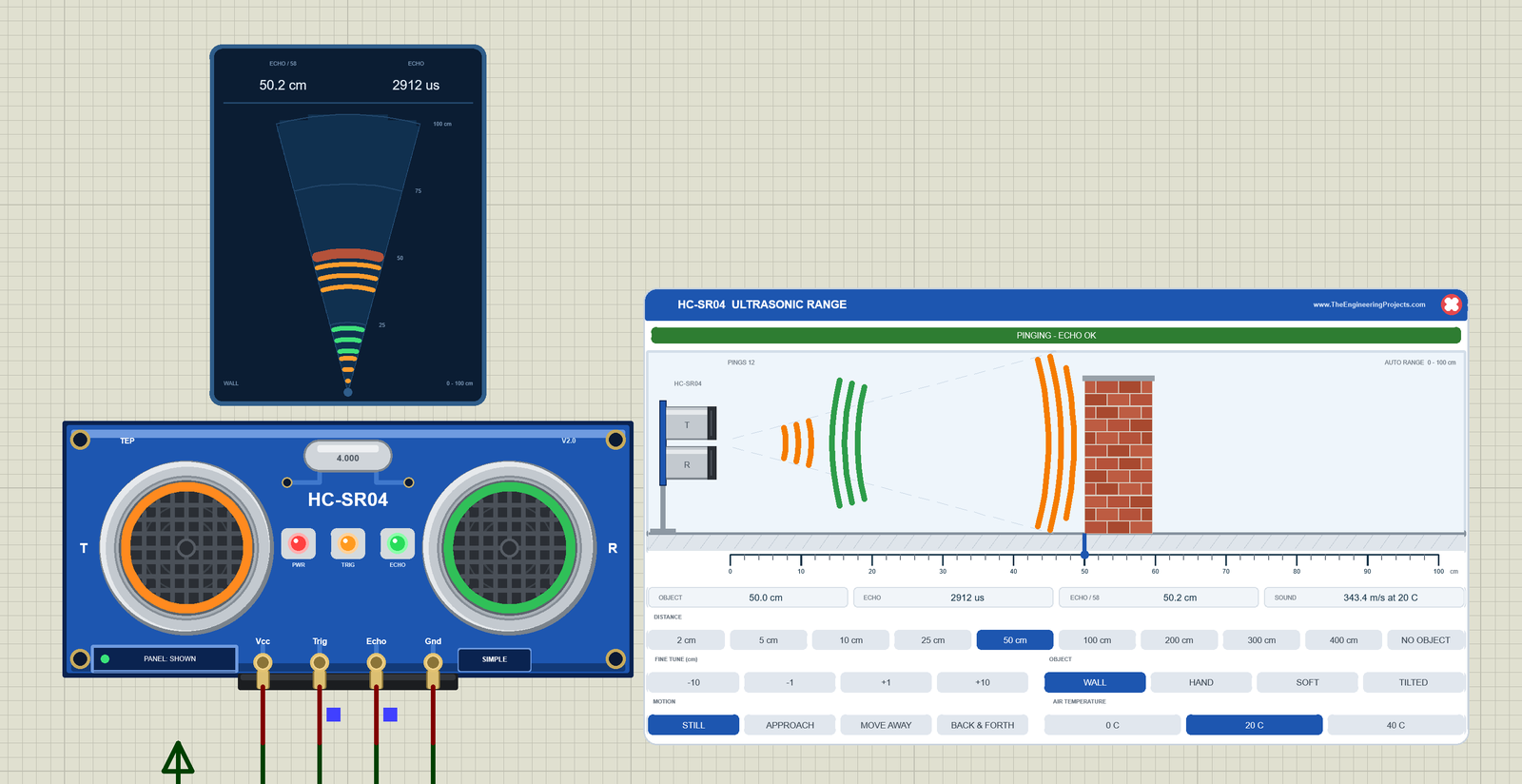
We drew the sensor as a clean TEP board in the blue of the real module: two silver transducers with a dark mesh face (T on the left, R on the right), the 4.000 MHz crystal between them, the white "HC-SR04" print, four gold mounting holes and the header Vcc, Trig, Echo, Gnd at the bottom. Here is U1, the Simple device, with a wall at 50 cm:
The Glowing Rings and the LEDs
The T ring glows orange when the clicks go out, and the R ring glows green when the echo comes back. Between the transducers sit three LEDs: PWR (red, the supply), TRIG (orange, 120 ms after every accepted TRIG pulse) and ECHO (green, while ECHO is HIGH). All three are a TEP addition: the real HC-SR04 has no LED at all. They flash with every ping, so a screenshot catches them on or off.
The Sonar Screen
Above the board stands the sonar screen, also a TEP addition: the beam from above (15 degrees each side) with range rings, the object as a band, and the sound itself, orange arcs going out and green arcs coming back, slowed down so you can see them. On top: ECHO / 58 (50.2 cm, what the demo prints) and the ECHO time (2912 us).
Pinout
The four pins keep the order of the real header: VCC, TRIG, ECHO, GND.
| Pin | What it does | Demo connection |
|---|---|---|
| VCC | Power (+5 V) | +5V terminal |
| TRIG | Input: a HIGH pulse of 10 us starts a ping | Arduino D9 |
| ECHO | Output: HIGH for the echo time | Arduino D8 (the input capture pin) |
| GND | Ground | Ground terminal |
LEDs and Indicators
| Indicator | What it shows |
|---|---|
| T ring (orange) | The 40 kHz clicks go out |
| R ring (green) | The echo is back |
| PWR LED (red) | The supply is connected (TEP addition) |
| TRIG LED (orange) | An accepted TRIG pulse, 120 ms (TEP addition) |
| ECHO LED (green) | ECHO is HIGH (TEP addition) |
| Sonar screen | The beam, the object, the sound out and back, ECHO / 58 and the ECHO time (TEP addition) |
| PANEL / OPEN PANEL, SIMPLE / ADVANCE | The panel button and the device badge |
Component Properties
| Property | Meaning | Default |
|---|---|---|
| DISTANCE | Start distance in cm, 2 to 400 (0 = no object) | 50 |
| OBJECT | WALL, HAND, SOFT or TILTED | WALL |
| MOTION | STILL, APPROACH, AWAY or SWING (= BACK & FORTH) | STILL |
| TEMP | Air temperature in C | 20 |
| NOISE | Measurement noise in cm, a random spread on every ping | 0 |
| NOECHO | How long ECHO stays HIGH without an echo: ms, REAL (170 ms, like many real modules) or STUCK (until power off, a known fault of some modules) | 38 |
| ECHODELAY | TRIG falling to ECHO rising, in us (slow clones: about 2250) | 450 |
| MAXRANGE | The farthest echo in cm, up to 500 | 400 |
| PANEL | Simple only: the panel at the start of a run, OPEN or CLOSED | OPEN |
DISTANCE, OBJECT, MOTION and TEMP give the start of every Run, so each Run begins the same way. The panel style comes from the device (Simple or Advance), not from a property you set.
HC-SR04 Simple: The Ultrasonic Range Panel
Beside the Simple board sits the HC-SR04 ULTRASONIC RANGE panel (on the right of the image above). It is the scene in front of the sensor, and everything on it is live:
| Part | What it does |
|---|---|
| Header, red X | HC-SR04 ULTRASONIC RANGE; the X closes the panel |
| Banner | The sensor's state: PINGING - ECHO OK, NO ECHO with the reason, TOO CLOSE, TRIG TOO SHORT, ECHO STUCK HIGH, WAITING FOR A TRIG PULSE or NO POWER |
| Side view | The sensor on its stand, the beam, the object and the sound arcs; PINGS counts the pings |
| Ruler | AUTO RANGE 0 - 50, 100, 200 or 400 cm; click it or the scene to place the object |
| OBJECT readout | Where the object is now |
| ECHO | The ECHO time of the last ping, measured on the pin |
| ECHO / 58 | What the demo sketch computes from that ECHO time |
| SOUND | The speed of sound at the air temperature |
| DISTANCE | 2, 5, 10, 25, 50, 100, 200, 300, 400 cm or NO OBJECT |
| FINE TUNE (cm) | -10, -1, +1, +10 |
| OBJECT buttons | WALL (echoes up to 400 cm), HAND (150 cm), SOFT (a cushion, 100 cm), TILTED (never) |
| MOTION | STILL, APPROACH (20 cm/s, stops at 3 cm), MOVE AWAY (20 cm/s, to 450 cm), BACK & FORTH (10 - 150 cm, 8 s for a round trip) |
| AIR TEMPERATURE | 0 C, 20 C, 40 C (331.3, 343.4, 355.5 m/s) |
In the start image, the green banner says PINGING - ECHO OK, and the readouts say OBJECT 50.0 cm, ECHO 2912 us, ECHO / 58 50.2 cm and SOUND 343.4 m/s at 20 C. OBJECT is the scene; ECHO / 58 is what your Arduino measures.
25 cm: a Closer Wall
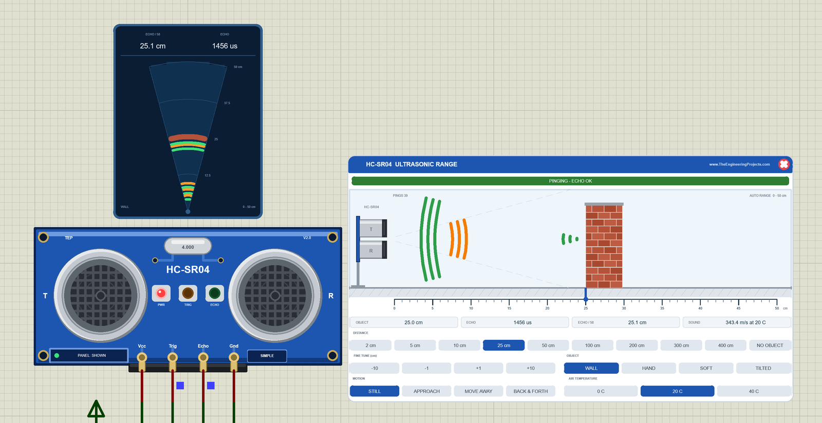
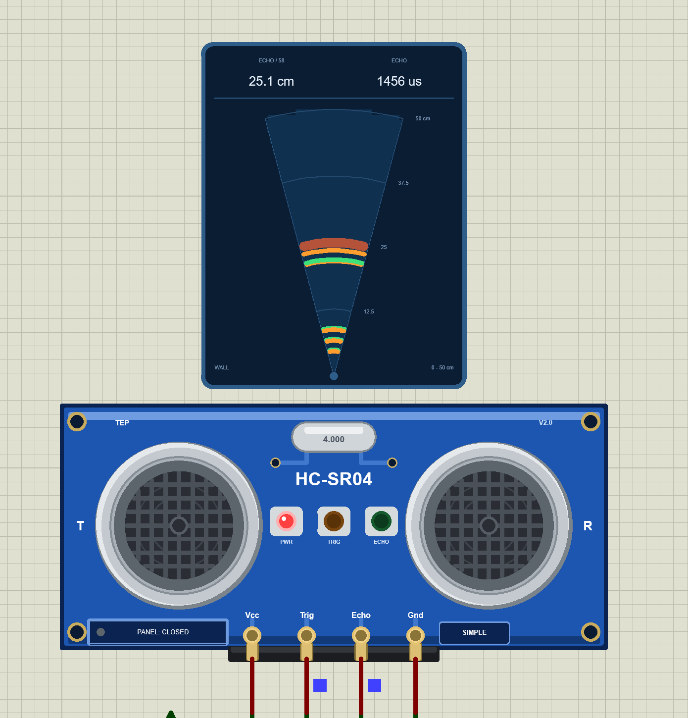
Click 25 cm. The wall moves closer, the ruler zooms in to 0 - 50 cm, and the next ping gives ECHO 1456 us, half of the 50 cm echo: 1456 / 58 = 25.1 cm. The sonar screen shows the same numbers. In this frame the rings and the TRIG and ECHO LEDs are dark: the picture was taken between two pings, and at one ping every 250 ms ECHO is HIGH for only 1.5 ms of each cycle.
HAND at 25 cm: Still an Echo
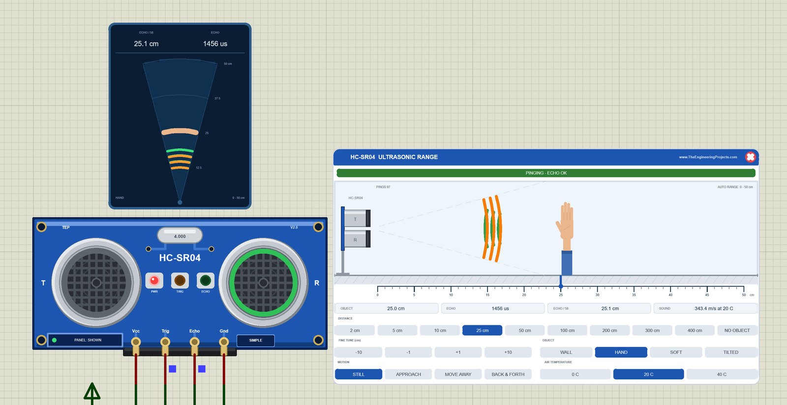
Click HAND. The wall becomes a hand on an arm, and the sonar screen says HAND. A hand is small and a weak reflector, so it echoes much less than a wall. At 25 cm that does not matter yet: the reading is the same 1456 us and 25.1 cm, and the R ring glows green as the echo arrives.
HAND at 200 cm: No Echo
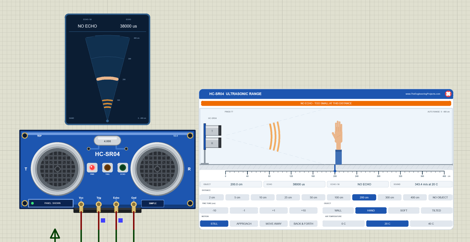
Now click 200 cm. The banner turns orange: NO ECHO - TOO SMALL AT THIS DISTANCE. In our model a hand echoes only up to 150 cm, a soft cushion up to 100 cm, and a tilted board never (it reflects the sound away). ECHO stays HIGH for the full 38000 us, and the arcs on the sonar screen only go out. The demo sketch stops waiting after 30 ms and prints "Out of range".
BACK & FORTH: a Moving Object
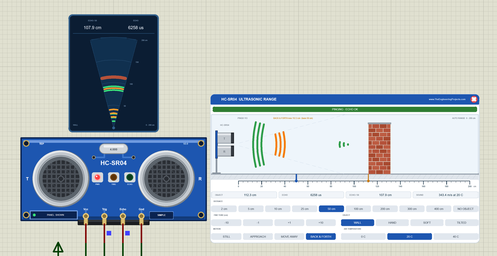
Click 50 cm and WALL again, then BACK & FORTH. The wall now swings between 10 and 150 cm, one round trip in 8 s. The distance you set stays the base: the 50 cm button stays lit, the ruler keeps a blue marker at 50 cm, and an amber marker shows where the wall is now. The side view says "BACK & FORTH now 112.3 cm (base 50 cm)", and the ruler zooms out to 0 - 200 cm.
Look at the readouts: OBJECT 112.3 cm, but ECHO / 58 = 107.9 cm (ECHO 6258 us). That is right: OBJECT is where the wall is now, ECHO / 58 is where the last ping found it, up to 250 ms ago, and the wall moves at 35 cm/s. A ping always lags a moving object. The panel never marks a preset you picked before; only a moving object keeps its base preset lit.
Closing the Panel
Click the red X in the panel's header: the panel disappears, the board button says PANEL: CLOSED with a grey dot, and the sensor keeps running. Click PANEL to bring the panel back. Here, U1 measures the wall at 25 cm with the panel closed:
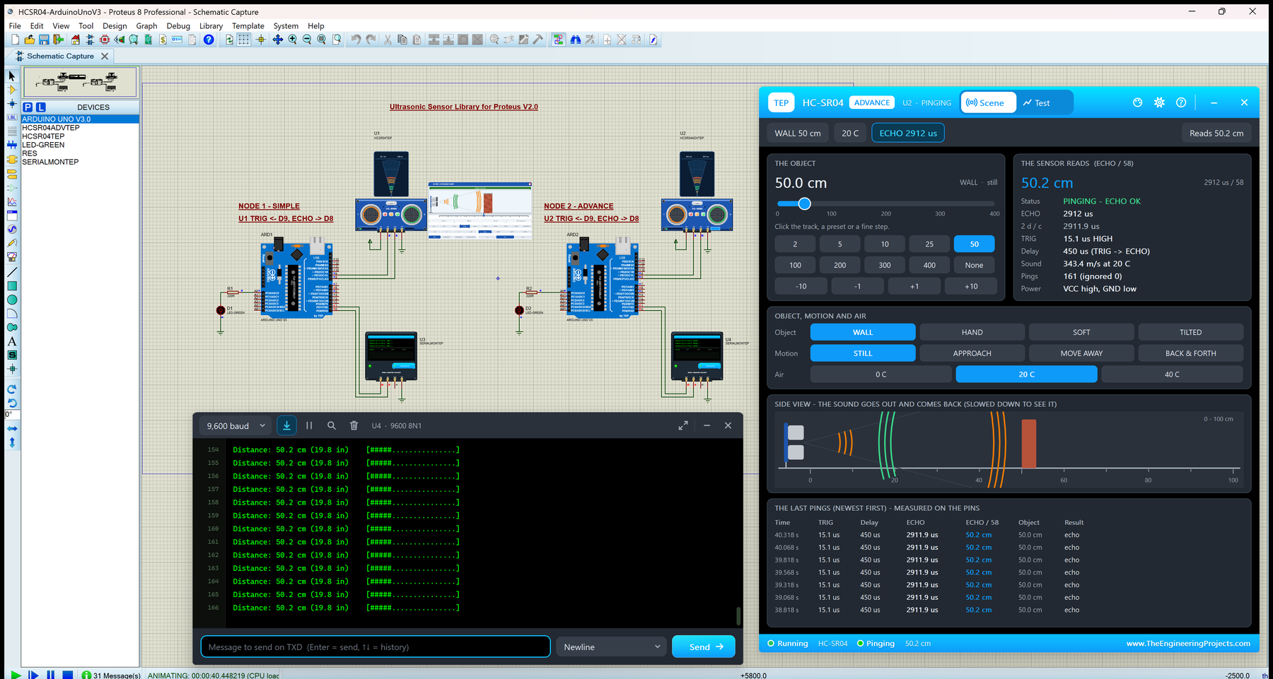
HC-SR04 Advance: The Pop-Up Sonar Window
The Advance device keeps only the board and its sonar screen on the schematic. Here is U2, measuring the wall at 50 cm:
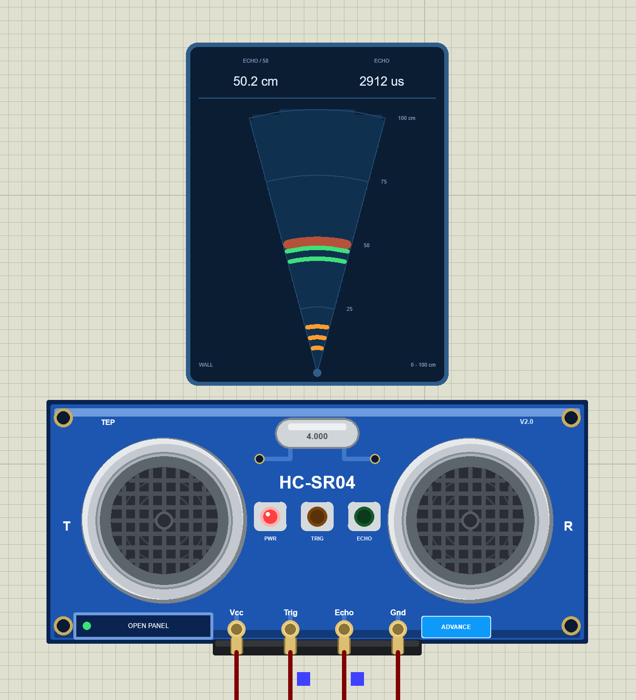
At Run, the "TEP HC-SR04 Advance" pop-up opens with the look of our TEP Serial Monitor and no Windows title bar: move it by its header, resize or minimise it, and reopen it with OPEN PANEL after you close it. The header shows the state (here U2 · PINGING), the Scene and Test tabs and the palette (theme), gear (Settings) and ? (Help) icons. The blue bar at the bottom repeats the state: Running, Pinging, 50.2 cm.
The Scene Page
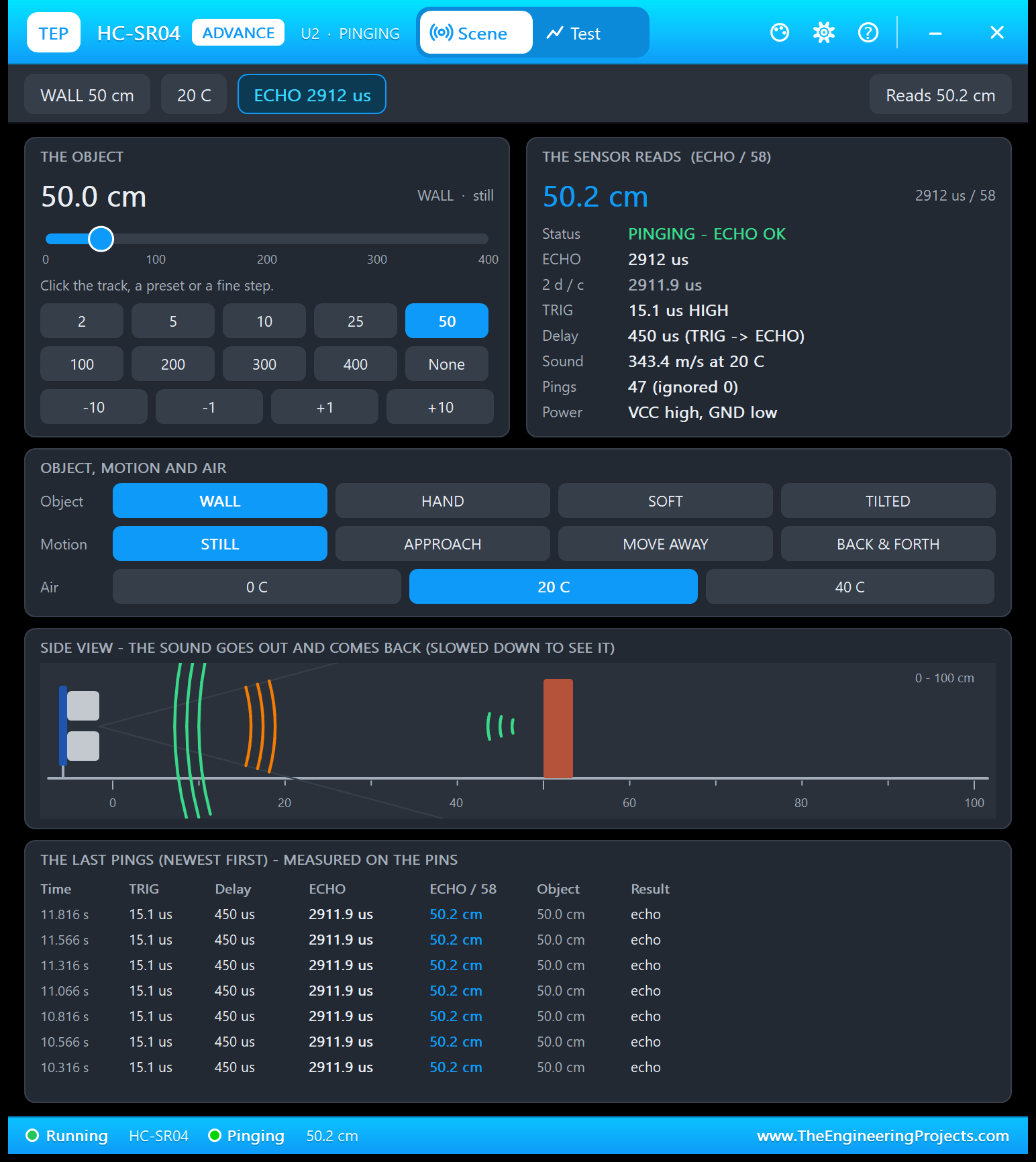
- THE OBJECT: 50.0 cm (WALL · still), a slider from 0 to 400 cm, presets and fine steps.
- THE SENSOR READS (ECHO / 58): 50.2 cm, PINGING - ECHO OK, ECHO 2912 us, the exact 2 d / c = 2911.9 us, TRIG 15.1 us HIGH, a delay of 450 us, the sound at 343.4 m/s, Pings 47 (ignored 0) and the power.
- OBJECT, MOTION AND AIR and a SIDE VIEW with the sound arcs.
- THE LAST PINGS - MEASURED ON THE PINS: the time, TRIG, delay, ECHO, ECHO / 58, the object and the result of each ping.
Notice TRIG 15.1 us: the sketch asks for 10 us with delayMicroseconds(10), but the digitalWrite() calls around it take time too. That is fine; the module needs at least 10 us. The ping times 10.316 ... 11.816 s are exactly 250 ms apart, the demo's rhythm.
The Test Page: Four Measured Sonar Test Tools
The four tools on the Test tab only place the object (and give the scene back afterwards) and read the module's own logs of TRIG pulses and pings. They never talk to your Arduino, so every number is what your sketch and the module really did, timed with the simulation clock. A tool stops when your sketch sends no TRIG for 3 s. Each ends with a bold "Good for:" line. All results come from U2 with the demo sketch at 20 C.
1. Echo Timing: Is Your Formula Right?
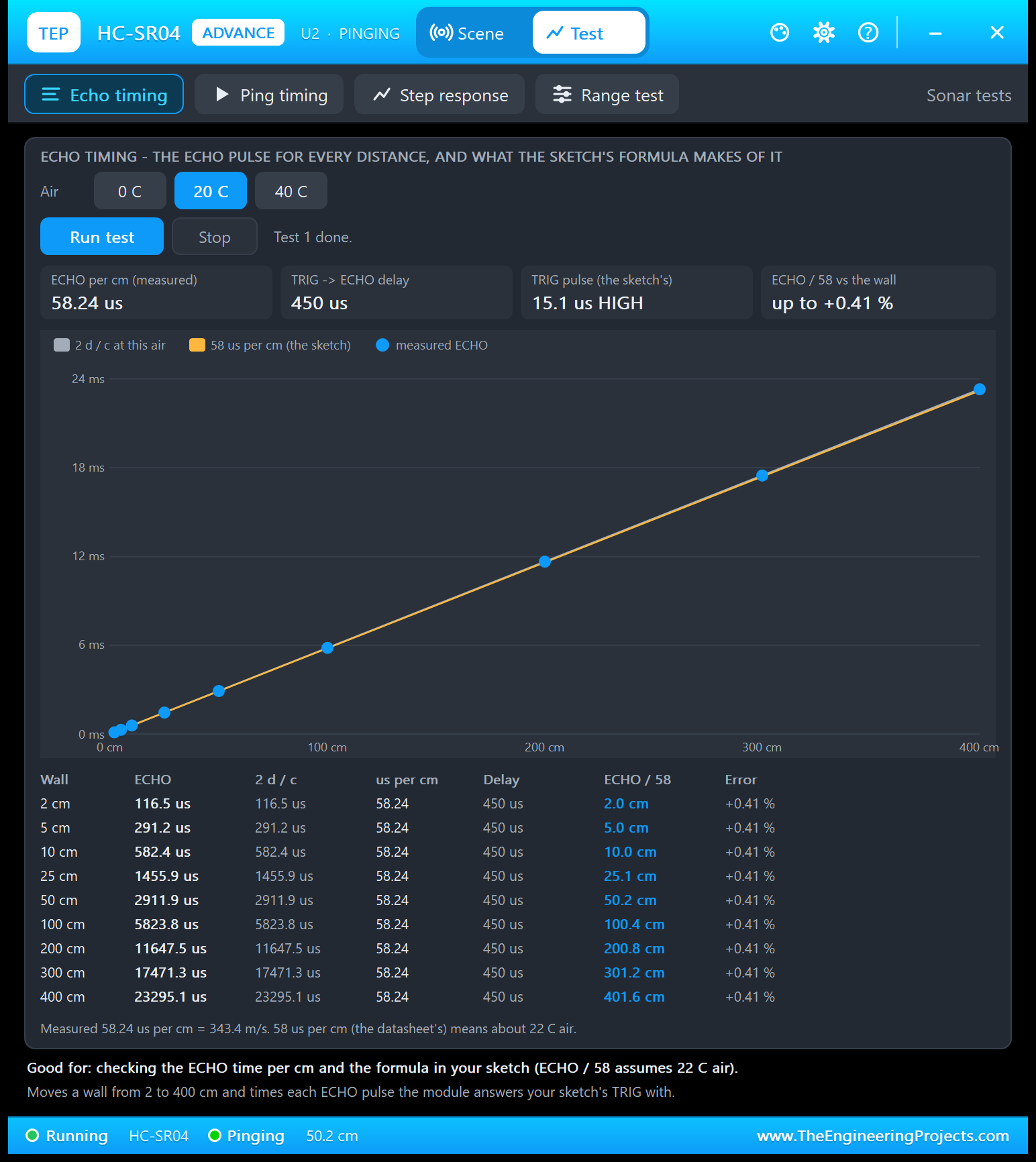
Good for: "checking the ECHO time per cm and the formula in your sketch (ECHO / 58 assumes 22 C air)." Choose the air (0, 20 or 40 C) and click Run test. The tool moves a wall to 2, 5, 10, 25, 50, 100, 200, 300 and 400 cm and times the ECHO pulse your sketch's next TRIG gets at each one:
| Wall | ECHO | ECHO / 58 | Error |
|---|---|---|---|
| 2 cm | 116.5 us | 2.0 cm | +0.41 % |
| 5 cm | 291.2 us | 5.0 cm | +0.41 % |
| 10 cm | 582.4 us | 10.0 cm | +0.41 % |
| 25 cm | 1455.9 us | 25.1 cm | +0.41 % |
| 50 cm | 2911.9 us | 50.2 cm | +0.41 % |
| 100 cm | 5823.8 us | 100.4 cm | +0.41 % |
| 200 cm | 11647.5 us | 200.8 cm | +0.41 % |
| 300 cm | 17471.3 us | 301.2 cm | +0.41 % |
| 400 cm | 23295.1 us | 401.6 cm | +0.41 % |
Every ECHO equals 2 d / c to 0.1 us, so the slope is 58.24 us per cm = 343.4 m/s, and the ECHO / 58 column is exactly what the demo prints. The error is +0.41 % at every distance, because it comes from the formula, not from the sensor. In the chart, the orange 58 us per cm line (what the sketch assumes) almost covers the measured one. At 0 C or 40 C the slope becomes 60.37 or 56.25 us per cm.
2. Ping Timing: How Often Does Your Sketch Ping?
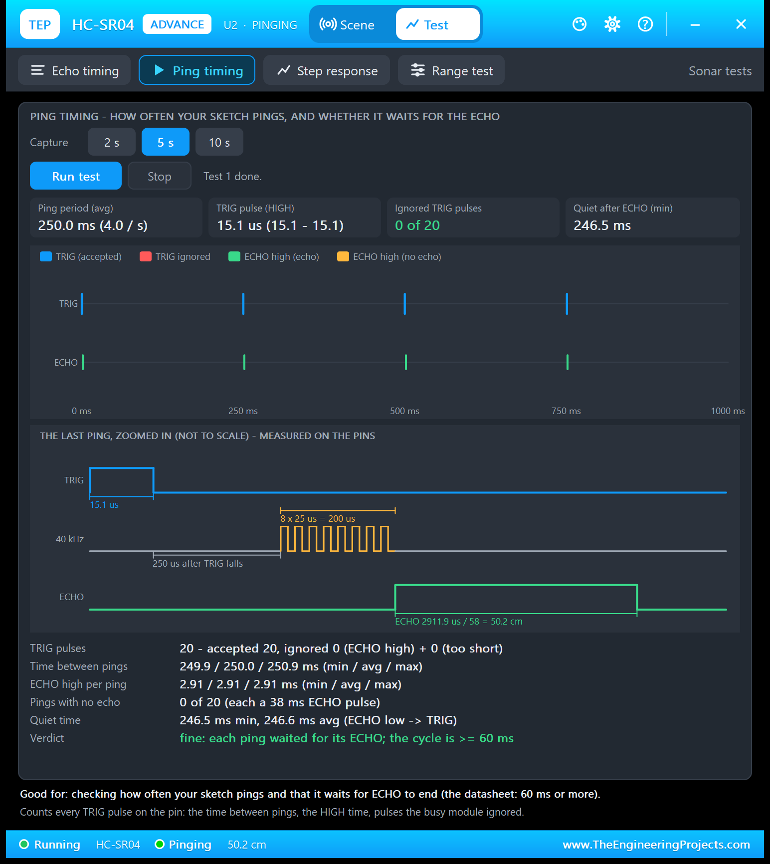
Good for: "checking how often your sketch pings and that it waits for ECHO to end (the datasheet: 60 ms or more)." Choose a 2, 5 or 10 s capture and click Run test. The tool counts every TRIG pulse on the pin:
| Result | U2 with the demo sketch (5 s) |
|---|---|
| TRIG pulses | 20: accepted 20, ignored 0 (ECHO high) + 0 (too short) |
| Time between pings | 249.9 / 250.0 / 250.9 ms (min / avg / max), 4.0 per second |
| TRIG pulse (HIGH) | 15.1 us |
| ECHO high per ping | 2.91 ms |
| Pings with no echo | 0 of 20 (each would be a 38 ms ECHO pulse) |
| Quiet time (ECHO low until the next TRIG) | 246.5 ms min, 246.6 ms avg |
| Verdict | fine: each ping waited for its ECHO; the cycle is 60 ms or more |
Below the 1 s timeline, THE LAST PING, ZOOMED IN draws the datasheet's timing diagram with numbers measured on the pins: TRIG HIGH for 15.1 us, the burst of 8 x 25 us = 200 us starting 250 us after TRIG falls, and ECHO HIGH for 2911.9 us (not to scale). Want to see a problem? Type EVERY 20 on U4, set the object to None and capture again: the TRIG pulses that arrive during the 38 ms no-echo pulse are counted as ignored.
3. Step Response: How Quickly Does Your Sketch See a New Distance?
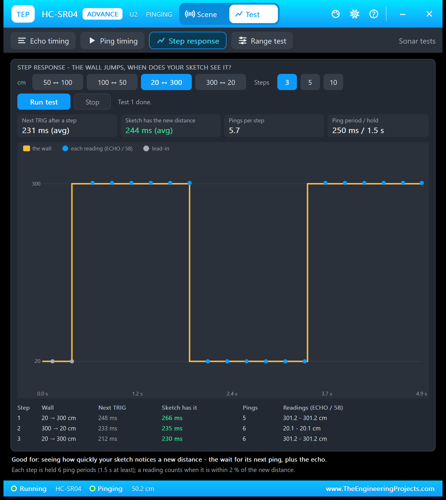
Good for: "seeing how quickly your sketch notices a new distance - the wait for its next ping, plus the echo." Choose the steps (50 to 100, 100 to 50, 20 to 300 or 300 to 20 cm) and 3, 5 or 10 steps. The tool starts with a flat lead-in (the grey dots at 20 cm), then makes the wall jump and holds each step for 6 ping periods (1.5 s at least). A reading counts when it is within 2 % of the new distance. Every reading is kept:
| Step | Wall | Next TRIG | Sketch has it | Pings | Readings (ECHO / 58) |
|---|---|---|---|---|---|
| 1 | 20 to 300 cm | 248 ms | 266 ms | 5 | 301.2 cm |
| 2 | 300 to 20 cm | 233 ms | 235 ms | 6 | 20.1 cm |
| 3 | 20 to 300 cm | 212 ms | 230 ms | 6 | 301.2 cm |
Two things add up: the wait for the sketch's next ping (up to one ping period, here 212 to 248 ms) and the ping itself. At 300 cm the echo takes about 18 ms (266 - 248 ms); at 20 cm about 2 ms (235 - 233 ms). The first reading after each step was already right. Want faster answers? Ping more often with EVERY, but keep 60 ms or more between pings.
4. Range Test: Where Does the Echo Stop?
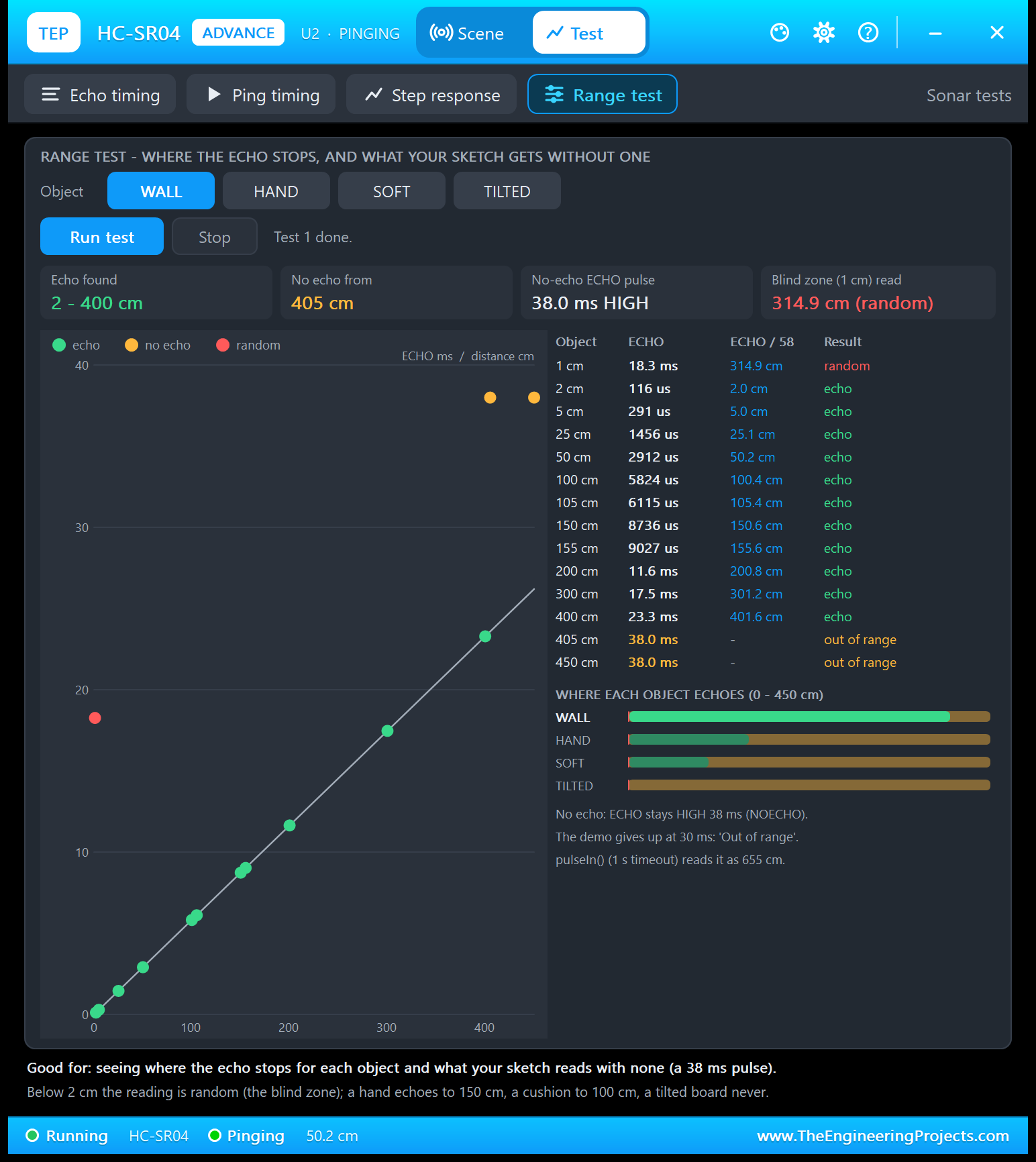
Good for: "seeing where the echo stops for each object and what your sketch reads with none (a 38 ms pulse)." Choose WALL, HAND, SOFT or TILTED and click Run test. The tool puts the object at 14 distances from 1 to 450 cm and records the ECHO pulse of a ping at each:
| Object at | ECHO | ECHO / 58 | Result |
|---|---|---|---|
| 1 cm | 18.3 ms | 314.9 cm | random |
| 2 cm | 116 us | 2.0 cm | echo |
| 5 cm | 291 us | 5.0 cm | echo |
| 25 cm | 1456 us | 25.1 cm | echo |
| 50 cm | 2912 us | 50.2 cm | echo |
| 100 cm | 5824 us | 100.4 cm | echo |
| 105 cm | 6115 us | 105.4 cm | echo |
| 150 cm | 8736 us | 150.6 cm | echo |
| 155 cm | 9027 us | 155.6 cm | echo |
| 200 cm | 11.6 ms | 200.8 cm | echo |
| 300 cm | 17.5 ms | 301.2 cm | echo |
| 400 cm | 23.3 ms | 401.6 cm | echo |
| 405 cm | 38.0 ms | - | out of range |
| 450 cm | 38.0 ms | - | out of range |
A wall echoes from 2 to 400 cm and not from 405 cm: there, ECHO stays HIGH for 38.0 ms. At 1 cm, in the blind zone, the ping gave a random 18.3 ms (314.9 cm). The 105 and 155 cm points sit just beyond the limits of the cushion and the hand, and the bars "WHERE EACH OBJECT ECHOES" sum it up: the wall to 400 cm, the hand to 150 cm, the cushion to 100 cm, the tilted board nowhere.
Read the note under the bars: "pulseIn() (1 s timeout) reads it as 655 cm." A sketch that calls pulseIn() without its own timeout turns "no echo" into a believable 655 cm. Always pass a timeout, as the demo does (30 ms).
Settings and Help
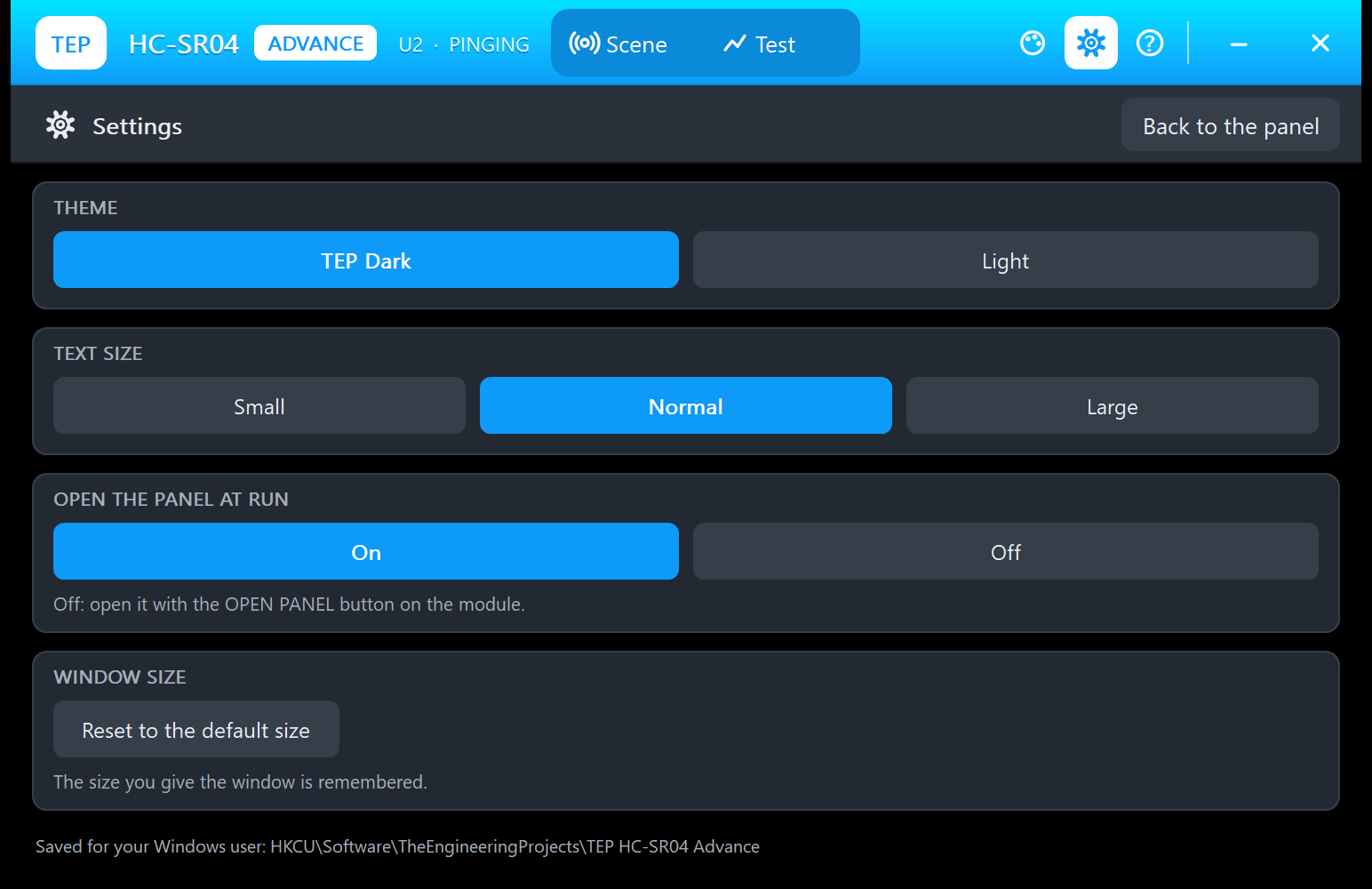
The gear opens Settings: the theme, the text size, whether the panel opens at Run, and the window size, saved for your Windows user.
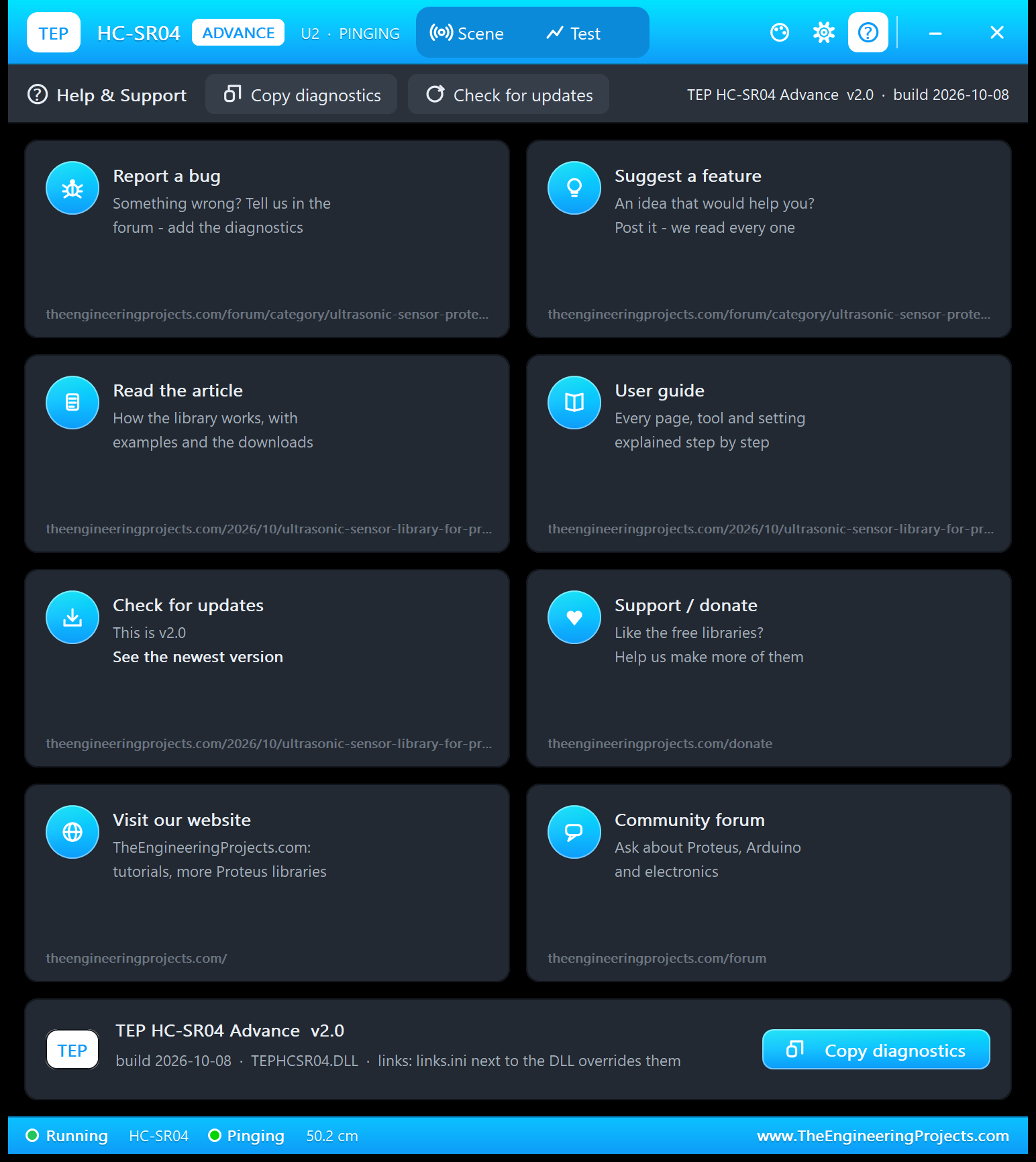
The ? icon opens Help & Support: eight cards with their links (report a bug and suggest a feature on the ultrasonic sensor board of our forum, this article, the user guide, updates, donate, our website and the forum), Check for updates, and Copy diagnostics for a bug report: the sensor, the scene, the timing, the last pings and the test results. A links.ini file next to the DLL can change the links.
HC-SR04 Distance Meter with Arduino in Proteus
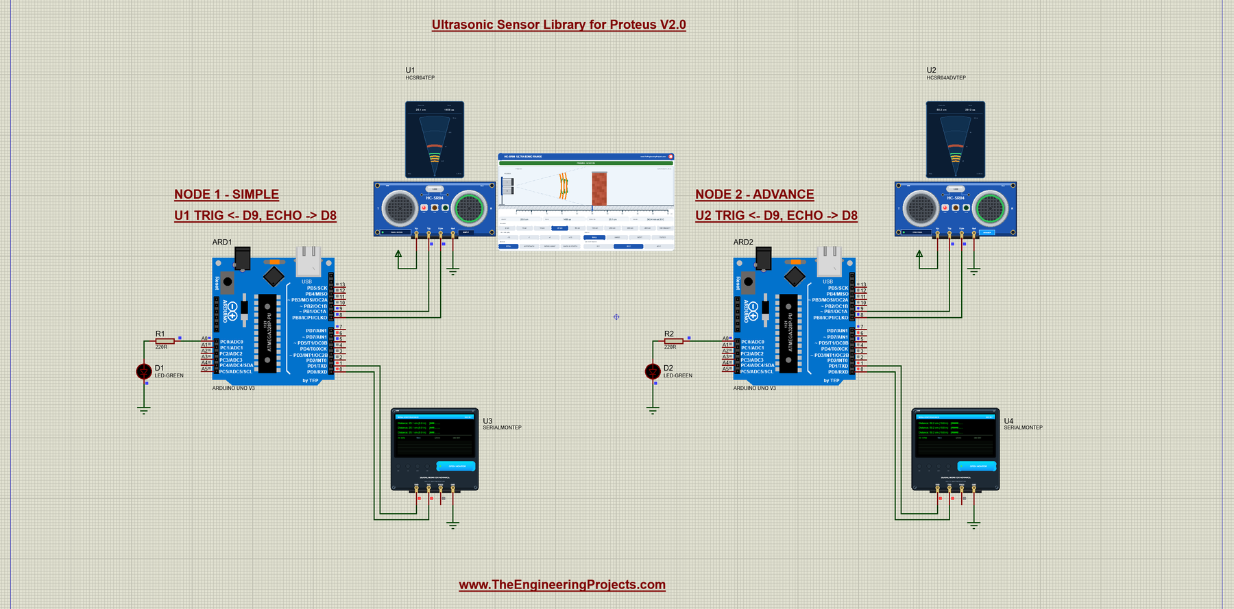
Open HCSR04-ArduinoUnoV3.pdsprj from the Proteus Simulation folder, with HCSR04_Distance.hex and both DLLs beside it. Its two Arduino UNOs from our Arduino Library for Proteus V3.0 run the same HEX file:
- NODE 1 - SIMPLE: UNO 1 (ARD1) with the HC-SR04 Simple (U1), the green "way is clear" LED D1 on A0 and Serial Monitor U3.
- NODE 2 - ADVANCE: UNO 2 (ARD2) with the HC-SR04 Advance (U2), the LED D2 on A0 and Serial Monitor U4.
Wiring
| From | To | Why |
|---|---|---|
| HC-SR04 VCC / GND | +5V terminal / ground | Power (the PWR LED lights) |
| HC-SR04 TRIG | Arduino D9 | The Arduino starts a ping |
| HC-SR04 ECHO | Arduino D8 | The echo pulse, timed by Timer1 input capture (ICP1) |
| LED + 220 ohm | A0 to GND | The way is clear: more than 50 cm, or nothing in range |
| Serial Monitor RXD / TXD / GND | Arduino D1 / D0 / ground | Shows what the Arduino prints, sends what you type |
| Serial Monitor RXD2 | Not connected | The HC-SR04 has no serial line to watch |
Why D8 for ECHO? D8 is the only input capture pin of the UNO's ATmega328P (see our Introduction to Arduino UNO). With pulseIn() any digital pin works (many tutorials use D10), but the capture needs D8. The sketch also drives D5, D6 and D7 for green, yellow and red parking LEDs, if you want to add them.
Why Timer1 Input Capture and Not pulseIn()?
pulseIn() counts how often its loop turns while the pin is HIGH. But every 1.024 ms the UNO's millis() interrupt (Timer0) runs for a few microseconds, and pulseIn() misses those turns. So long pulses read about 0.5 - 0.6 % short: 50 cm reads 49.9 cm. A real UNO does the same.
Input capture works in hardware. Timer1 counts in steps of 0.5 us, and at the moment the ECHO pin on D8 changes, the chip copies the count into the register ICR1, even while an interrupt runs. The reading is exact to 0.5 us, which is why the panel's ECHO / 58 and the Serial Monitor agree. METHOD PULSEIN lets you compare both live.
The Arduino Code
The sketch needs no library. A ping starts with a clean 10 us HIGH pulse on TRIG:
// TRIG HIGH for 10 us = "measure now!"
void sendTrigPulse() {
  digitalWrite(TRIG_PIN, LOW);        // start from a clean LOW level
  delayMicroseconds(2);
  digitalWrite(TRIG_PIN, HIGH);
  delayMicroseconds(10);
  digitalWrite(TRIG_PIN, LOW);
}
In setup(), Timer1 is set to run freely, without interrupts, in 0.5 us steps:
  // Timer1 counts freely in steps of 0.5 us (16 MHz / 8), no interrupts.
  TCCR1A = 0;
  TCCR1B = _BV(CS11);
  TIMSK1 = 0;
The measurement gives up after 30 ms, which covers a 400 cm echo (about 23 ms) plus the module's delay, but not the 38 ms no-echo pulse:
const unsigned long ECHO_TIMEOUT_US = 30000UL;
const uint16_t ECHO_TIMEOUT_TICKS = 60000U;       // the same 30 ms in Timer1 steps of 0.5 us
Now the capture itself. The sketch waits for an old ECHO pulse to end, captures the rising edge, then the falling edge, and returns the difference in microseconds:
// The ECHO pulse in microseconds, timed by Timer1 (0 = no echo in 30 ms).
float readEchoTimeCapture() {
  sendTrigPulse();
  const uint16_t start = TCNT1;
  // 1. like pulseIn(): if an old ECHO pulse is still HIGH, wait for its end
  while (digitalRead(ECHO_PIN) == HIGH) {
    if ((uint16_t)(TCNT1 - start) > ECHO_TIMEOUT_TICKS) return 0;
  }
  // 2. the rising edge: the hardware copies Timer1 into ICR1 at that moment
  TCCR1B |= _BV(ICES1);               // capture a rising edge
  TIFR1 = _BV(ICF1);                  // clear an old capture
  if (!waitForCapture(start)) return 0;
  const uint16_t rise = ICR1;
  // 3. the falling edge
  TCCR1B &= ~_BV(ICES1);              // capture a falling edge
  TIFR1 = _BV(ICF1);
  if (!waitForCapture(start)) return 0;
  const uint16_t fall = ICR1;
  // Timer1 counts 0.5 us steps
  return (uint16_t)(fall - rise) * 0.5;
}
waitForCapture() watches the capture flag ICF1. The uint16_t arithmetic keeps the time right even when the 16-bit timer wraps around during a measurement:
bool waitForCapture(uint16_t start) {
  while (!(TIFR1 & _BV(ICF1))) {
    if ((uint16_t)(TCNT1 - start) > ECHO_TIMEOUT_TICKS) return false;
  }
  return true;
}
The classic method stays in the sketch, so you can compare. It is one line:
float readEchoTimePulseIn() {
  sendTrigPulse();
  // pulseIn() waits for ECHO to go HIGH, then counts how long it stays HIGH.
  return pulseIn(ECHO_PIN, HIGH, ECHO_TIMEOUT_US);
}
The conversion to centimetres uses the rounded 58, as most tutorials do (remember: that means about 22 C air):
// Converting time into distance:
//   Sound travels about 343 m/s at 20 C = 0.0343 cm per microsecond.
//   The sound goes TO the object and BACK, so 1 cm of distance = 2 cm of travel:
//   2 / 0.0343 = 58.3 us per cm. Most tutorials round it to 58.
//   distance (cm) = echo time (us) / 58
const float US_PER_CM = 58.0;
Each reading measures the echo, handles "no echo", and converts:
  // 1. Measure the echo time.
  float echoTime = readEchoTime();
  readings++;

  // 2. No echo (0): nothing within range.
  if (echoTime == 0) {
    outOfRange++;
    lastEchoUs = 0;
    Serial.println(F("Out of range"));
    setParkingLeds(HIGH, LOW, LOW);   // the way is clear: green
    return;
  }

  // 3. Turn the time into a distance.
  float distanceCm = echoTime / US_PER_CM;
  float distanceIn = distanceCm / CM_PER_INCH;
The line "Distance: 50.2 cm (19.8 in)" is padded with spaces, so the bar graphs of all lines start in the same column:
  int printed = 0;
  printed += Serial.print(F("Distance: "));
  printed += Serial.print(distanceCm, 1);   // 1 digit after the decimal point
  printed += Serial.print(F(" cm ("));
  printed += Serial.print(distanceIn, 1);
  printed += Serial.print(F(" in)"));
  while (printed < BAR_COLUMN) {            // pad with spaces up to the bar
    Serial.print(' ');
    printed++;
  }
  printBar(distanceCm);
The loop uses millis() instead of delay(), so the rhythm stays at 250 ms and typed commands are answered at once:
void loop() {
  readCommands();

  // Wait until the reading interval has passed since the last measurement.
  // Using millis() instead of delay() keeps the rhythm steady, whatever the
  // printing takes, and the commands are answered at once.
  if (readIntervalMs == 0 || millis() - lastReadTime < readIntervalMs) {
    return;
  }
  lastReadTime = millis();
  takeReading();
}
EVERY changes the rhythm and reminds you of the datasheet's 60 ms:
      Serial.print(F("Reading every "));
      Serial.print(readIntervalMs);
      if (readIntervalMs < 60) Serial.println(F(" ms (the datasheet asks for 60 ms or more)"));
      else Serial.println(F(" ms"));
The settings live in RAM, so a new Run brings back the start values. To change the sketch, export a new HEX file and load it into both UNOs; see How to get the HEX file from Arduino. New to Arduino? Start with our Arduino Tutorial for Beginners.
Serial Monitor Commands
| Command | What it does |
|---|---|
| HELP | The command list (two lines) |
| STATUS | Two lines: the interval, the method, the formula and the timeout; then the last echo time and distance, the number of readings and how many were out of range |
| READ | One reading now |
| EVERY ms | The time between readings, 10 to 60000 ms (start: 250); EVERY 0 stops them |
| RAW ON / RAW OFF | Also print the echo time of each reading, for example "echo 2912.0 us (Timer1 capture)" |
| METHOD CAPTURE / PULSEIN | Timer1 input capture on D8 (the default, exact to 0.5 us) or pulseIn() |
How to Run the Demo
- Press Run. Both Serial Monitors (9600 baud) and U2's pop-up open, and U3 and U4 print "Distance: 50.2 cm (19.8 in)" four times a second. At 50 cm the A0 LEDs stay off (50 is not more than 50).
- On U1's panel, click 100 cm (100.4 cm, D1 lights), 2 cm, 400 cm (401.6 cm) and NO OBJECT ("Out of range"). Try HAND, SOFT, TILTED and the motions, then the AIR buttons: at 0 C a 50 cm wall reads 52.0 cm, at 40 C 48.5 cm.
- Use U3's quick buttons; type METHOD CAPTURE, RAW OFF and EVERY 250 to go back.
- On U2, try the Scene page and the four tools on the Test tab.
- Close U2's window and reopen it with OPEN PANEL; close U1's panel with its red X and reopen it with PANEL.
Ultrasonic Sensor Proteus Simulation Results
The Serial Monitor in Its Simple Interface
Both monitors in this demo run in the Simple interface of our TEP Serial Monitor, as in every monitor screenshot here. Only the log, the send box and one slim toolbar row stay visible (baud rate, follow, pause, search and clear), so the window stays small.
- Switch to it: right-click the log and choose Simple interface, or press Ctrl+Shift+U.
- Back to the full view: click the corner button (the expand arrows at the top right), press Esc or Ctrl+Shift+U, or right-click and choose Full interface.
- Your choice is remembered.
Type commands in the send box and press Enter; the quick buttons come back with the full view. Every line the sketch prints is shorter than 80 characters, so it fits. Read all about the monitor in TEP Serial Monitor Advance for Proteus.
Start-Up
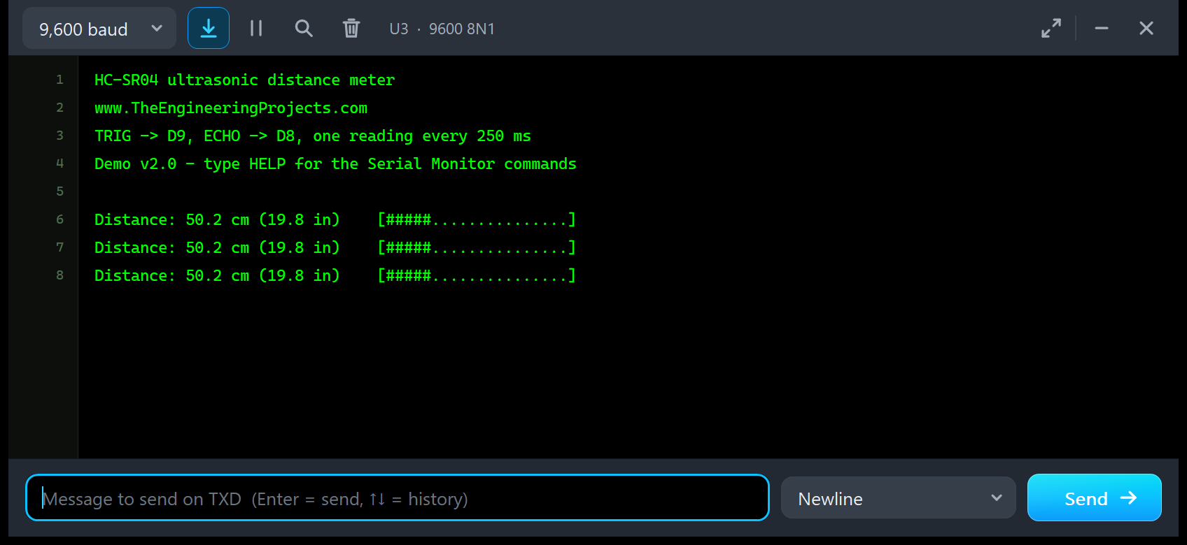
After Run, U3 prints the title "HC-SR04 ultrasonic distance meter", our website and the wiring line (TRIG on D9, ECHO on D8, one reading every 250 ms). Then come the new v2.0 line, an empty line and the readings:
Demo v2.0 - type HELP for the Serial Monitor commands

Distance: 50.2 cm (19.8 in)    [#####...............]
Distance: 50.2 cm (19.8 in)    [#####...............]
Distance: 50.2 cm (19.8 in)    [#####...............]
This is the classic reading line: the distance in cm and in inches, and a bar graph with one # for every 10 cm (a full bar means 200 cm or more). 50.2 cm gives five.
A Moving Object
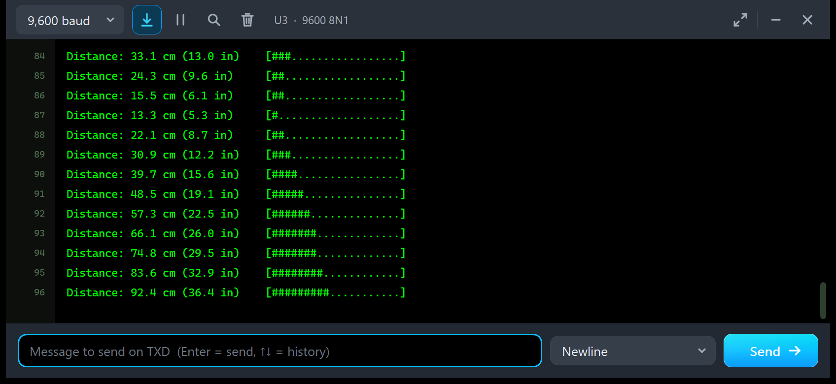
Distance: 33.1 cm (13.0 in)    [###.................]
Distance: 24.3 cm (9.6 in)     [##..................]
Distance: 15.5 cm (6.1 in)     [##..................]
Distance: 13.3 cm (5.3 in)     [#...................]
Distance: 22.1 cm (8.7 in)     [##..................]
Distance: 30.9 cm (12.2 in)    [###.................]
Distance: 39.7 cm (15.6 in)    [####................]
Distance: 48.5 cm (19.1 in)    [#####...............]
Distance: 57.3 cm (22.5 in)    [######..............]
Distance: 66.1 cm (26.0 in)    [#######.............]
Distance: 74.8 cm (29.5 in)    [#######.............]
Distance: 83.6 cm (32.9 in)    [########............]
Distance: 92.4 cm (36.4 in)    [#########...........]
Here, U1 runs BACK & FORTH. The wall moves 35 cm/s, so it travels 8.75 cm between two readings: 33.1, 24.3, 15.5 cm. Then it reaches its turning point at 10 cm and comes back, which is why 15.5 is followed by 13.3 and then 22.1 cm. From 57.3 cm on, the reading is more than 50 cm, and the sketch switches the A0 LED on. The bar graph grows and shrinks with the distance: a simple text radar.
HELP
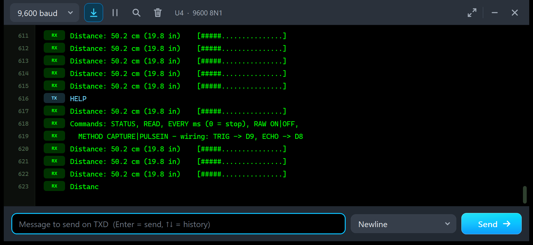
Type HELP on U4. Once you send something, the log marks your lines TX and the sketch's lines RX. The answer has two lines: "Commands: STATUS, READ, EVERY ms (0 = stop), RAW ON|OFF," and a second line with "METHOD CAPTURE|PULSEIN" and the wiring (TRIG on D9, ECHO on D8). One reading came first: the sketch was busy with that ping and answered on its next loop turn.
STATUS, READ and METHOD PULSEIN
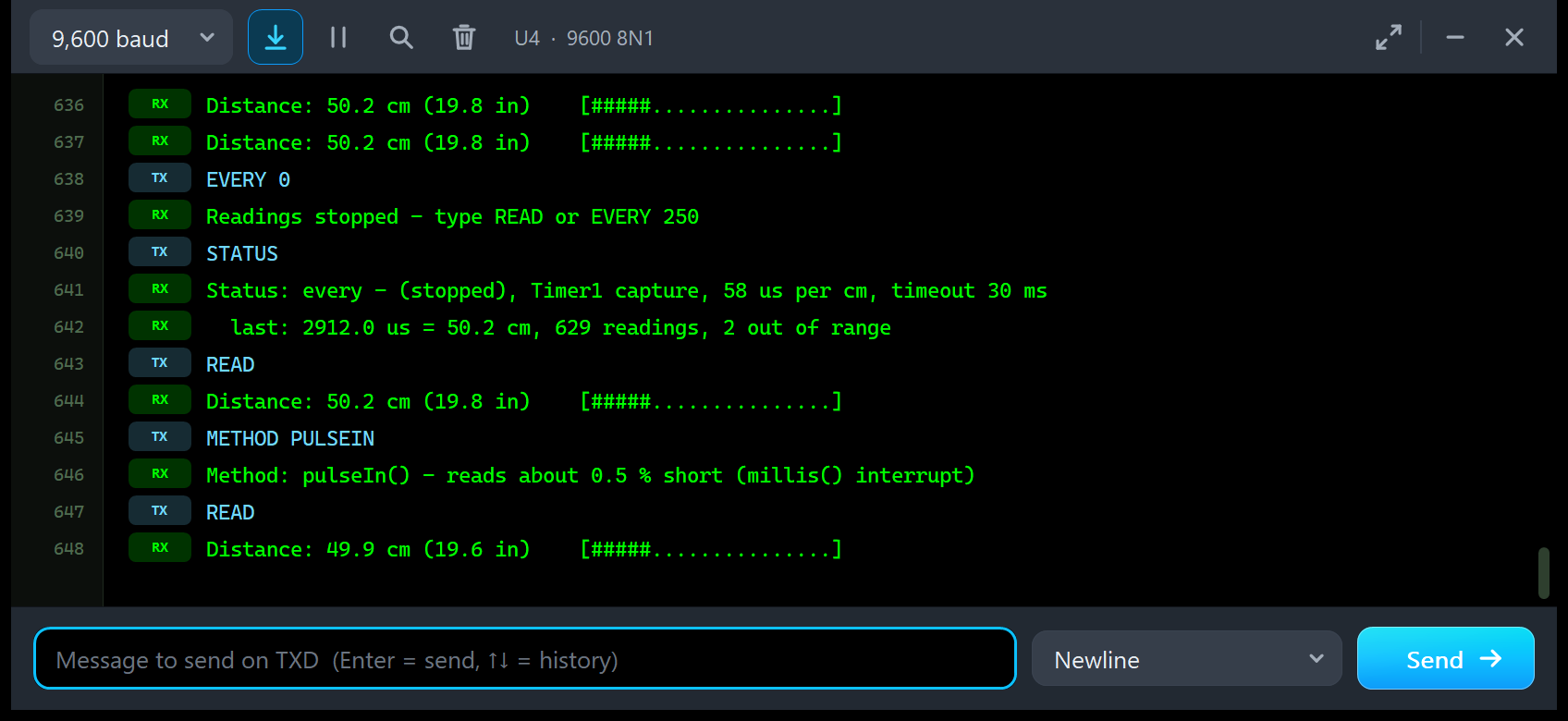
EVERY 0
Readings stopped - type READ or EVERY 250
STATUS
Status: every - (stopped), Timer1 capture, 58 us per cm, timeout 30 ms
  last: 2912.0 us = 50.2 cm, 629 readings, 2 out of range
READ
Distance: 50.2 cm (19.8 in)    [#####...............]
METHOD PULSEIN
Method: pulseIn() - reads about 0.5 % short (millis() interrupt)
READ
Distance: 49.9 cm (19.6 in)    [#####...............]
This is the best test of the two methods. EVERY 0 stops the automatic readings, so nothing gets in between. STATUS shows the settings and the last reading: 2912.0 us = 50.2 cm (the model's 2911.9 us in Timer1's 0.5 us steps), after 629 readings, 2 of them out of range. READ takes one reading with Timer1 input capture: 50.2 cm. Then METHOD PULSEIN switches to pulseIn(), and the next READ gives 49.9 cm (19.6 in), for the same wall at the same distance. That is the Timer0 interrupt that pulseIn() misses. Type METHOD CAPTURE and EVERY 250 to go back.
Troubleshooting
- "Out of range" all the time: check VCC and GND (the PWR LED must be lit), TRIG on D9, ECHO on D8, and the scene: NO OBJECT, TILTED, a HAND beyond 150 cm and SOFT beyond 100 cm give no echo. The banner says which.
- TRIG TOO SHORT: your TRIG pulse is shorter than 5 us; send 10 us.
- Readings about 0.5 % short: that is pulseIn(); use METHOD CAPTURE or accept it.
- A reading jumps around below 2 cm: the blind zone, as on the real module.
- Pings get lost at a fast rhythm with no echo: TRIG pulses during the 38 ms no-echo pulse are ignored. Ping every 60 ms or slower.
- ECHO STUCK HIGH: NOECHO is STUCK; run the simulation again or change NOECHO.
- An object drawn on the schematic changes nothing: the panel, the pop-up and the properties are the scene.
- No simulation, no panel or no monitor window: TEPHCSR04.DLL or TEPSERIALMON.DLL is missing from MODELS and the project folder; click OPEN MONITOR on a closed monitor.
- No Advance pop-up: click OPEN PANEL on the board, or turn "Open the panel at Run" back on.
- Your own sketch receives with SoftwareSerial: that does not work in Proteus 8.5; use the hardware Serial or AltSoftSerial.
Things to Know Before Using a Real HC-SR04
The demo sketch is plain Arduino code, so it runs on a real UNO and HC-SR04 too. Keep in mind:
- Supply: the classic HC-SR04 needs 5 V; the HC-SR04P and RCWL-9610 versions run from 3.3 to 5 V. The classic ECHO is a 5 V signal, so use a voltage divider for a 3.3 V board.
- Range: 2 to 400 cm on a flat, hard surface facing the sensor. A hand, cloth, foam and surfaces at an angle reflect much less; the model's HAND, SOFT and TILTED are rough guides.
- The beam is about 15 degrees each side; anything inside it can echo first, the floor too.
- Leave 60 ms or more between pings, so an old echo does not arrive in the next one.
- Temperature: about 0.6 m/s per degree C; ECHO / 58 is right at about 22 C.
- No echo: many real modules hold ECHO HIGH for about 170 ms, not 38 ms. Set NOECHO = REAL to try it, and always keep a timeout.
- pulseIn() on a real UNO reads about 0.5 % short too; Timer1 input capture does not.
Limitations of the Simulation
- Not modelled: the real beam shape and several objects at once (one object on the axis), floor echoes, multi-path, crosstalk between two sensors, humidity, the supply voltage (the digital model sees only high and low), and the serial / I2C modes of the HC-SR04P and RCWL-9610. The HAND, SOFT and TILTED limits are approximations.
- The model is our own implementation, written from the published HC-SR04 datasheets and user guides and from published measurements of real modules; it contains no third-party code. The HEX file contains the Arduino AVR core 1.8.6, which includes LGPL-licensed code; its source code is on GitHub.
- Speed: the demo runs at about 0.4 - 0.5 x real time with both pop-ups open.
- Tested in Proteus 8.5 in October 2026 (the demo, both panels, the four tools and every screenshot here) and with 3,023 automatic PC checks, all passed, 74 of them with the real demo sketch on two UNOs. Proteus 7 is not supported.
Want a distance sensor with a narrow laser beam instead of a sound cone? See our VL53L0X Sensor Library for Proteus. For a simple "something is close" signal, try our Infrared Sensor Library for Proteus V2.0, and to detect people moving in a room, our PIR Sensor Library for Proteus V4.0.
So, that was all about the Ultrasonic Sensor Library for Proteus V2.0. I hope the glowing transducers, the sonar screen, the moving objects and the four test tools make the HC-SR04 much easier to understand, so your distance meter works the first time you wire a real module. If you use the Ultrasonic Sensor Library for Proteus in a project, please share your feedback in the comments or in our forum, and if you have any questions, ask in the comments and I will help you out. Till the next tutorial, take care and have fun!