Hello friends, I hope you all are doing great. Today, I am going to share the new Flashing LED Library for Proteus. Blinking an LED is the first thing most of us ever do with an Arduino. But did you know that you can buy an LED that blinks all by itself, with no Arduino, no code and no timer? A flashing LED looks just like a normal 5 mm LED, but it hides a tiny chip inside its dome.
Flashing LED Library for Proteus
Latest version: V1.0 (November 2026, this tutorial)
Other component libraries: C945 Transistor · PC817 Optocoupler · Relay Module · Resistor · 5 mm LED · Designer Colour LED · Push Button · Active Buzzer · Electrolytic Capacitor · Ceramic Capacitor · Tantalum Capacitor · Film Capacitor · 1N4007 Diode · Zener Diode · Schottky Diode · Supercapacitor · Photodiode · RGB LED · Bridge Rectifier · Bi-Colour LED · SMD LED · Slide Switch · Toggle Switch · Rocker Switch · Micro Limit Switch · Emergency Stop Switch · SMD Resistor · Power Resistor · Resistor Network · Potentiometer · Trimmer Potentiometer · Slide Potentiometer · NTC Thermistor · DIP Switch · Fuse · Passive Buzzer · Mini Speaker · 7-Segment Display · LED Bar Graph · IR / UV LED · Small Transistors · TIP122 Darlington · N-MOSFET · P-MOSFET · PC817 Optocoupler · Filament Bulb · Power LED · Voltage Regulator · SCR and TRIAC · Inductor · Toroid Inductor · Crystal
Helping Tools
- Serial Monitor Advance: a serial terminal window for the UART of your board
- Serial Monitor Expert: the serial monitor with extra debugging tools
- LCD Library for Proteus V3.0: 16x2, 20x4 and I2C LCDs to show your readings
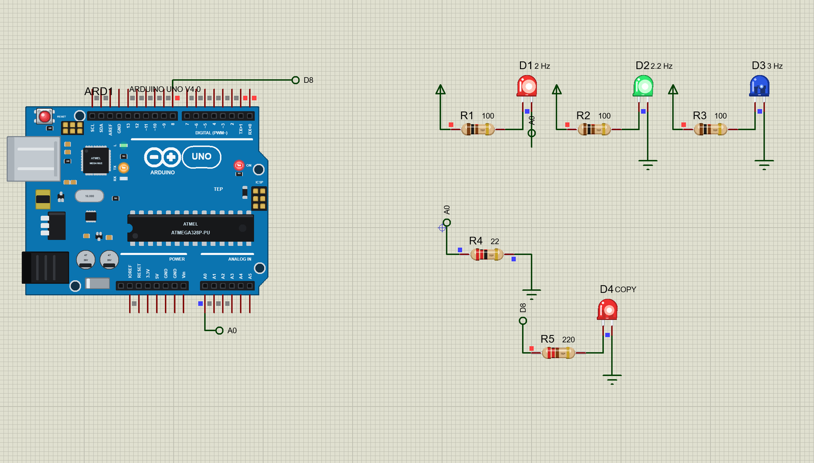
So we built one, at true scale, in red, green and blue, with the same real-looking dome as our other LEDs. Give it a steady supply and it just flashes. For the demo, three of them run from one supply at slightly different rates, so they slowly drift in and out of step like the indicators of cars at a traffic light. An Arduino sits on the side, doing no work at all except timing the flashes with a tiny sense resistor.
NOTICE: Our team has put a lot of effort into these small parts: the bodies, the animation and the pop-ups are all our own design, and you get them free. Your feedback is the fuel that keeps us going, so please tell us what you think in the comments below or in the Flashing LED board of our forum. And if our free libraries help you, you can buy us a coffee. So, let's get started with the Flashing LED Library for Proteus:
What is a Flashing LED?
A flashing LED, sometimes called a self-flashing or blinking LED, is an ordinary LED die with a second, even smaller chip beside it in the same dome. That chip is a tiny oscillator with a switch. Connect the part to a supply, and the chip turns the die on and off by itself, usually at about 1 to 3 flashes each second. If you look closely at a clear one, you can see the extra square of silicon on the lead frame, and sometimes a second bond wire.
They are used in toys, bicycle lights, model trains and warning signs, anywhere that a simple flash is wanted with no extra parts. You can also find versions that fade slowly through colours, using a more complicated chip and three dies. Inside, it is all the same idea: a whole small circuit, packed into a 5 mm dome.
| Feature | The real part | In the library |
|---|---|---|
| Dome | 5 mm | 210 thou, true scale |
| Legs | 2.54 mm apart, long leg + | 100 thou apart |
| Flash rate | about 1 to 3 Hz | 2 Hz by default, a property |
| Supply | about 3 V to 5 V | it needs about 2.5 V to run |
| Current while on | about 20 mA | set by your resistor |
Does It Need a Resistor?
This is the most common question. Some flashing LEDs have a current-limiting resistor built into the chip, and they can go straight on 3 V to 5 V. Others do not, and they need a series resistor like any LED. There is no way to tell by looking, so read the datasheet, or use a resistor to be safe. Our part behaves like the kind with no resistor, so our demo uses 100 ohm. If you want more on choosing that resistor, see our 5 mm LED Library for Proteus.
Can It Set the Time?
Not really. The oscillator in a flashing LED is a tiny resistor and capacitor on the chip, and nobody trims them. Two parts from the same bag can run at noticeably different speeds, and the rate changes with voltage and temperature. So you cannot use one as a clock. But that small difference is also what makes a row of them so nice to watch. They start together, slowly drift apart, and come together again.
Why Do They Drift?
Two flashers at 2 Hz and 2.2 Hz differ by 0.2 flashes a second. So every 5 seconds the faster one gains one whole flash, and the two line up again. This is a beat, the very same effect you hear when two guitar strings are almost in tune. The beat rate is simply the difference between the two rates. You will see exactly this in our demo, without a single line of code driving the LEDs.
Using It as a Simple Oscillator
Here is a neat trick that hobby designers enjoy. The current through a flashing LED is a square wave, so a flasher can drive other things. Put a small resistor in series and you have a voltage that switches at 2 Hz, ready to drive the base of a transistor. A flasher in series with a small active buzzer gives a beeping alarm. A flasher and a normal LED in series make two LEDs flash together. In each case the flasher replaces a timer chip, and a handful of parts besides.
What is a Sense Resistor?
Our demo has to detect the LED's current without getting in the way of it. The way to measure a current with a voltage pin is a sense resistor: a very small resistor in the current's path. By Ohm's law, the voltage across it is the current times the resistance. Here, 22 ohm at about 24 mA gives roughly 0.5 V, which is easy for A0 to see, and small enough that the LED hardly notices. Motor drivers and battery chargers use exactly the same idea, with far smaller resistors.
Inside the Tiny Chip
The chip beside the die is a very small integrated circuit, with no more than a few transistors, a resistor and a capacitor. A ring oscillator charges and discharges that capacitor at a slow, steady rate, and a divider stretches the result out to about two pulses a second. A final transistor acts as the switch in series with the LED die. All of it is powered through the same two legs as the LED, which is the clever part. While the die is off, a tiny current still flows to keep the clock running, and that is why our model has a small idle current.
Flasher or Blink Sketch?
You might wonder why anyone would use one when a blink sketch is so easy. A sketch needs a microcontroller, a pin, and the power and code to run them. A flasher needs a battery and a resistor. If all you want is a warning light on a bicycle, a charger or a model, then a flashing LED costs a few cents and it cannot crash. But when you need a certain rate, a pattern, or a response to something happening, then a microcontroller is the right tool. It is another good example of picking the simplest part that does the job.
Reading a Flasher with a Meter
Put a multimeter in series with a flasher, and you will see an odd thing: the reading jumps about at the flash rate. A slow meter averages it, and at a 50 % duty the reading is about half the real on current. So do not trust a meter here, and use the Average Current tile on our pop-up to see that same effect. It is also a good reminder that a current has a peak value and an average value, and that a part may care about either one.
Colours and Rates
Common flashers come in red, green, blue, yellow and white, in 3 mm and 5 mm sizes. Most run at about 1.5 Hz to 3 Hz. Fast versions at about 5 Hz are sold for warning lights. Slow fading RGB versions cycle through colours by themselves, using a more complex chip and three dies. Because a flasher draws so little between its flashes, a small coin cell can keep a simple warning light running for days on end, with nothing else to look after.
Features of the Flashing LED Library for Proteus
- The real look, at true scale: the same moulded dome as our 5 mm LED, in red, green and blue, with our small TEP signature.
- It flashes by itself: a built-in oscillator switches the current, with no code and no timer.
- A rate you can set: 2 Hz by default, from 0.2 Hz to 20 Hz, a property for each part.
- Its own clock: each part keeps its own time, so a row of them drifts in and out of step.
- A true LED: the diode law in the analog simulator, and too much current burns it out.
- A pop-up for every part: click it at Run for the live values, the series resistor, graphs, an event log and a check page.
- A complete package: about 1.8 MB with the library, our Arduino UNO V4.0, the demo's resistors and plain LED and the demo, without the source code of the models.
The Flashing LED in Proteus
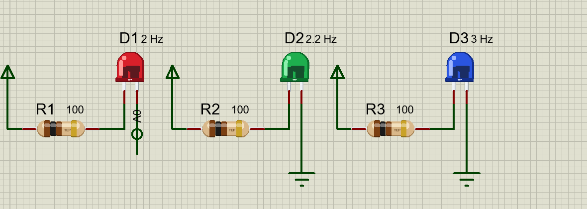
The three devices are LEDFLASHREDTEP, LEDFLASHGREENTEP and LEDFLASHBLUETEP in TEPLEDFLASH.LIB, under Optoelectronics, LEDs, with the prefix D and the model TEPLEDFLASH.DLL. Search LEDFLASH in Pick Devices. The pins are A and K, just like a normal LED.
The Properties
| Property | What it does |
|---|---|
| Forward voltage at 20 mA, V | the die: 2.0 V for red by default |
| Maximum current, mA | 30 by default |
| Flash rate, Hz | the flash rate, 2 by default |
Download Flashing LED Library for Proteus
Click the button below to download Flashing-LED-Library-for-Proteus-v1.0.zip (about 1.8 MB, without the source code of the models):
Flashing LED Library for Proteus V1.0- README.txt: installation, the demo, the properties, troubleshooting and the limits.
- Proteus Library Files:
TEPLEDFLASH.LIB,TEPRESISTOR.LIB,TEPLED5MM.LIBand ourArduinoV4TEP.LIB. - Proteus Model Files:
TEPLEDFLASH.DLL,TEPRESISTOR.DLL,TEPLED5MM.DLLandTEPARDUINO.DLL. - Arduino Code: the demo sketch.
- Proteus Simulation: the demo project, its HEX file and copies of the DLLs.
No Proteus yet? Read How to Download and Install Proteus 7 and 8. New to libraries? Follow How to Install a New Library in Proteus.
How to Install Flashing LED Library for Proteus
- Close Proteus and extract the whole zip file, for example to your Desktop.
- Copy the files from Proteus Library Files into the LIBRARY folder of Proteus.
- Copy the files from Proteus Model Files into the MODELS folder.
- Delete
TEPLEDFLASH.IDXfrom the LIBRARY folder if it is there. - Start Proteus, press P and search for LEDFLASH.
Demo: Three Flashers and a Watching Arduino
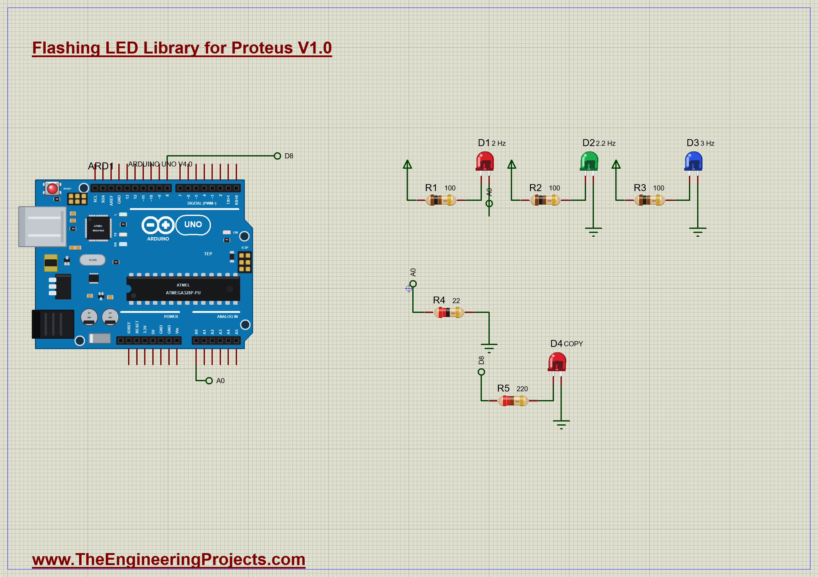
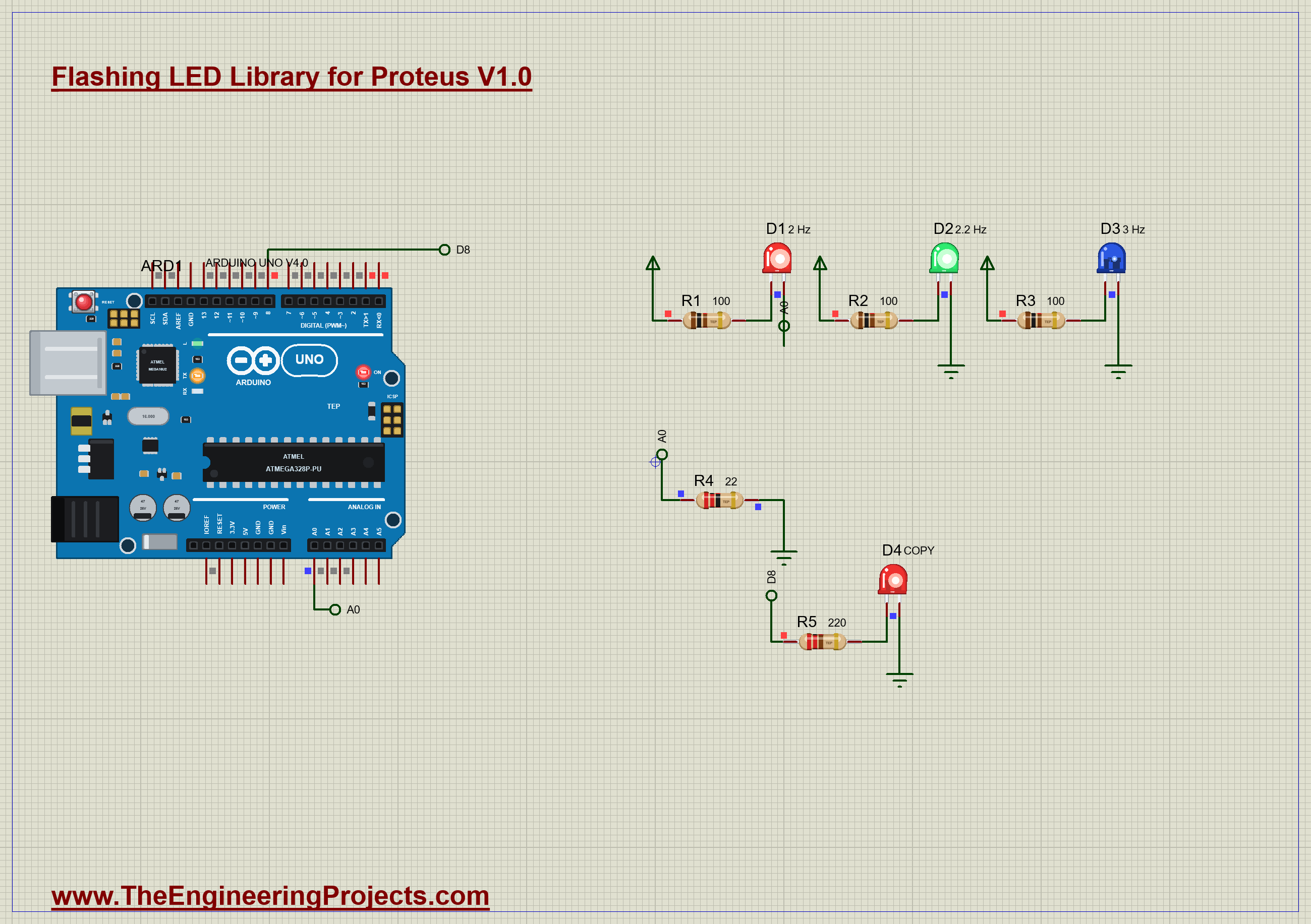
The three LEDs run straight from +5V through their own 100 ohm resistors: red D1 at 2 Hz, green D2 at 2.2 Hz, and blue D3 at 3 Hz. The Arduino does not drive them at all. It only watches D1, through R4, a 22 ohm sense resistor between D1 and GND. Each time D1 flashes, the sketch times it, and it copies the flash to a plain LED, D4, to show what it saw. Open Flashing-LED-ArduinoUnoV4.pdsprj. It runs on our Arduino UNO Library for Proteus V4.0, with its built-in monitor, the same window as our TEP Serial Monitor Advance for Proteus. The resistors are from our Resistor Library for Proteus.
| Part | Connection | Job |
|---|---|---|
| D1, red, 2 Hz | +5V through R1, K to A0 | the one being watched |
| D2, green, 2.2 Hz | +5V through R2, K to GND | drifts against D1 |
| D3, blue, 3 Hz | +5V through R3, K to GND | the fast one |
| R4, 22 ohm | A0 to GND | the sense resistor |
| D4 and R5 | D8 to GND | a plain LED, copying D1 |
Watching a Current
The sketch only reads A0 in a fast loop. With D1 on, A0 sits well above the noise, and with D1 off, it is near zero. Two levels are used, so that a reading on the edge cannot flicker. When the level rises past the top one, a flash has begun, and the sketch works out the time since the last one:
  if (!wasOn && level > ON_LEVEL) {
    wasOn = true;
    digitalWrite(COPY_PIN, HIGH);
    unsigned long period = now - lastRise;
Notice that the plain LED D4 is the only LED in this demo that the Arduino controls.
Run the Demo
Press Run, and the three LEDs start flashing at once. There is no code behind them: you could delete the Arduino from the sheet, and they would carry on. Click D1 to open its pop-up. The current in the tile jumps between about 24 mA and almost nothing:
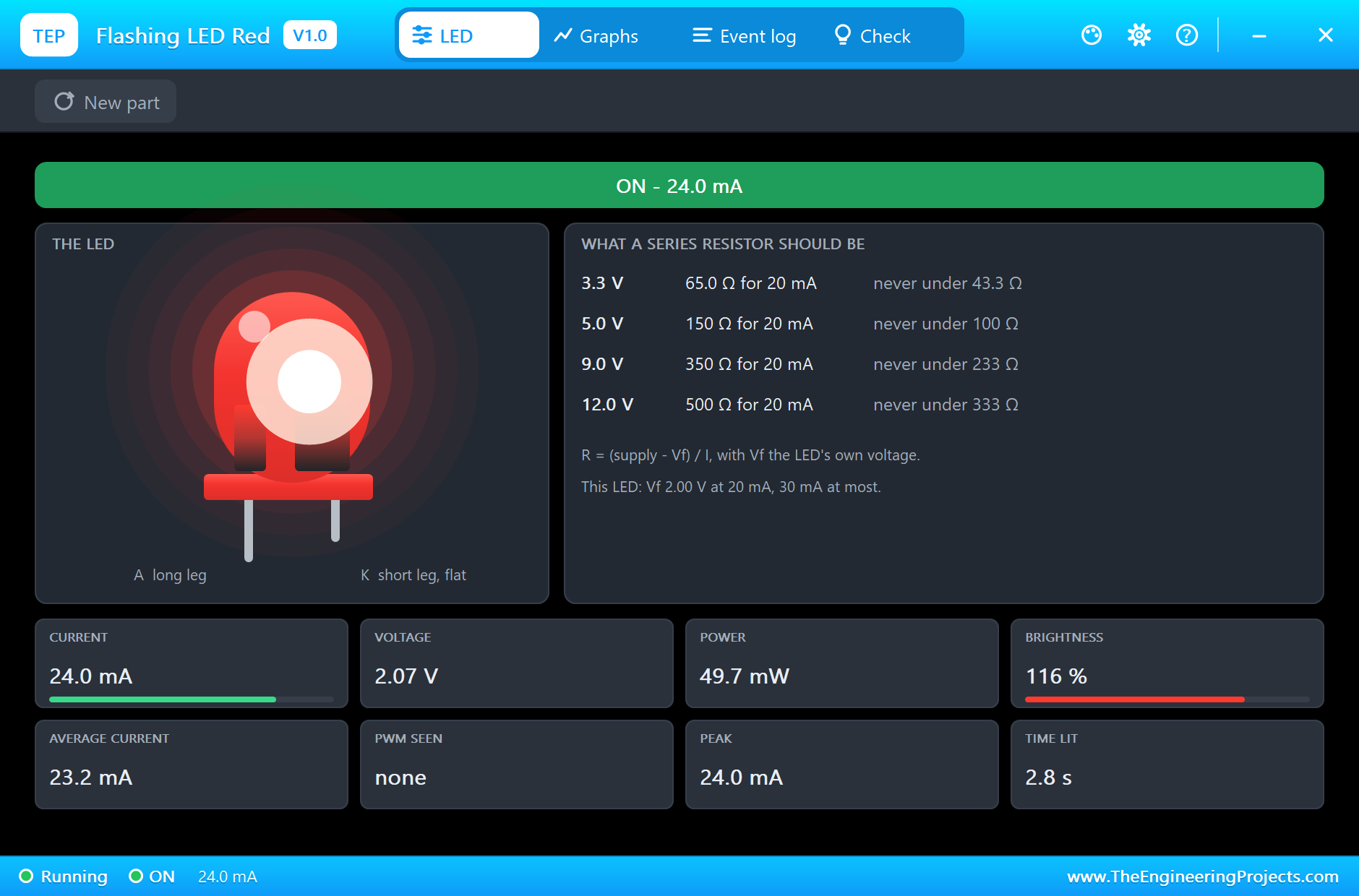
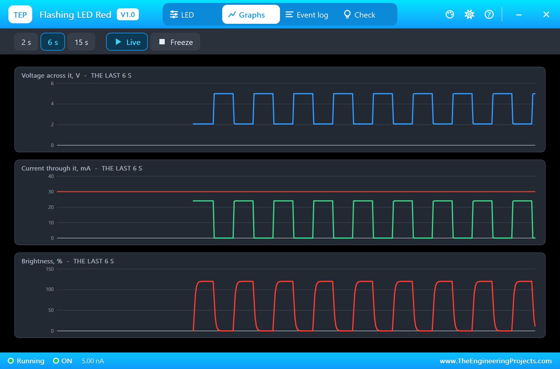
The Graphs tab is the clearest view. A steady supply goes in, and a square wave of current comes out:
Here is the complete circuit, truly running. Watch the three LEDs for a while. At first they flash together, then they slowly separate, and a few seconds later the red and green come back together:
The Arduino's View
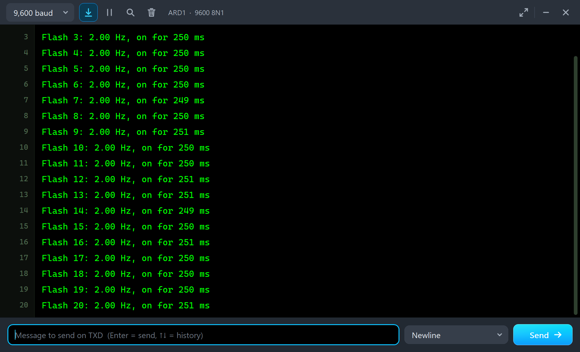
The monitor prints a line for each flash of D1, with its rate and its on time. It reads 2.00 Hz, on for 250 ms, exactly as set on the part:
The Log and the Check Page
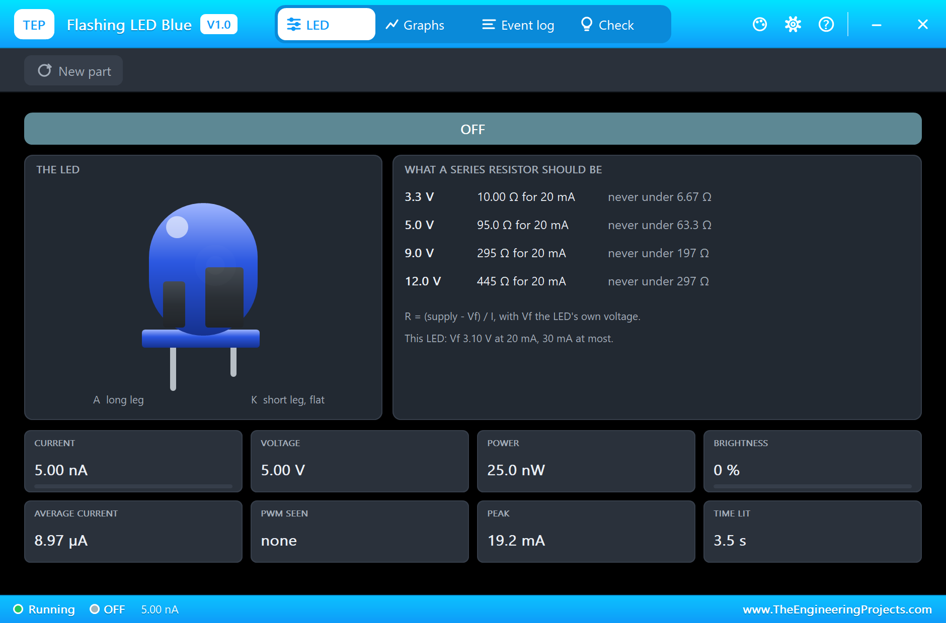
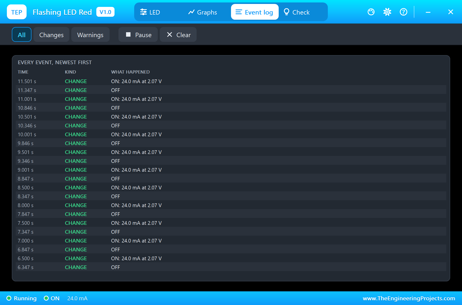
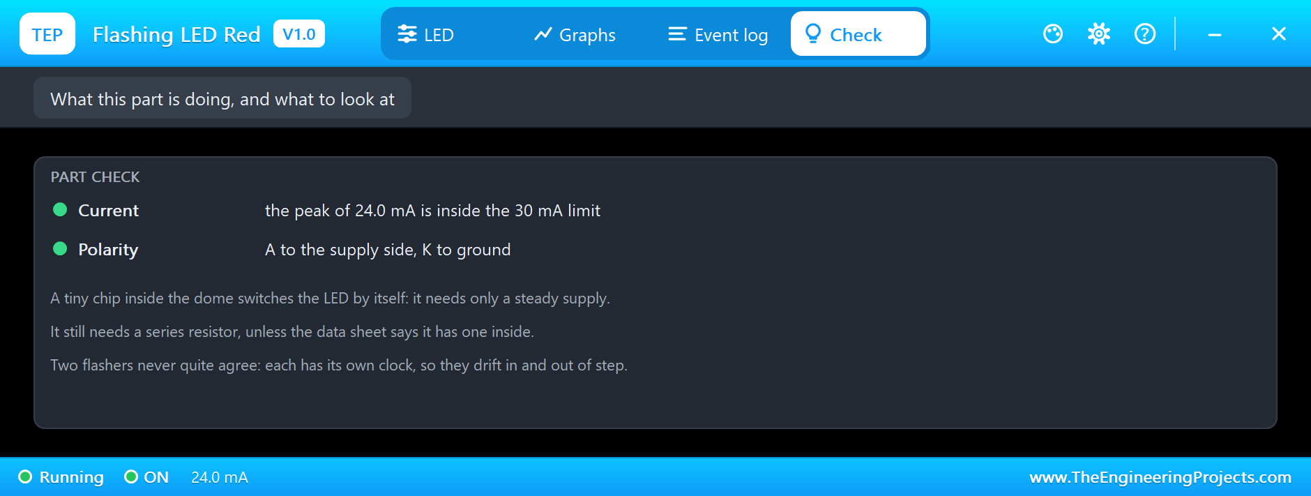
The Event log shows each change, and the Check page looks at the current against the limit:
Try It Yourself
- Change the green LED's flash rate to 2.05 Hz, and see how slow the beat becomes.
- Remove the Arduino, and check that the LEDs carry on flashing.
- Run D3 from a lower supply, and find the voltage where it stops.
- Change R1 to 47 ohm, and see the current rise on the pop-up.
- Print the time between red and green flashes, and watch it shrink.
Ideas to Extend the Demo
- Use a flasher to drive a small active buzzer as a beeping alarm.
- Drive a transistor from a flasher, and flash a bigger lamp.
- Count flashes for a minute, and see how close to the set rate it is.
- Build a railway crossing with two flashers and one Arduino.
Your Own Sketches
The demo sketch is in the zip file, and you can change it in the Arduino IDE. New to Arduino? Start with our Arduino Tutorial for Beginners. Export the compiled binary, and set the UNO's PROGRAM property to the new file. Our guide on How to get the HEX file from Arduino shows you where the file ends up.
Things to Know Before Using a Real Flashing LED
- Check the datasheet: a built-in resistor is not a given.
- Check the voltage: most stop working under about 3 V, and some do not like more than 5 V.
- Do not dim it with PWM: its chip needs a steady supply, and PWM confuses it.
- Do not expect accuracy: the rate differs from part to part.
- Mind the polarity: the long leg is the anode, as on a normal LED.
Troubleshooting
- It does not flash: the voltage across it is under about 2.5 V.
- It stays lit: set the flash rate property to a value you can see.
- BURNT OUT: use more ohms, then press New part.
- The pop-up does not open: click the LED while the simulation runs.
- The part is not simulated:
TEPLEDFLASH.DLLis missing from MODELS and from the project folder.
Limitations of the Simulation
- The rate does not change with voltage or temperature, and it is exact for each part.
- The sheet repaints at most four times a second, so a fast rate may look uneven.
- The chip's own start-up is left out.
- Arduino is a name of Arduino; this library is not made or endorsed by Arduino or Labcenter.
- Tested in Proteus 8.5 in October 2026 (the demo as shipped). Proteus 7 is not supported.
So, that was all about the Flashing LED Library for Proteus. I hope you enjoy seeing a whole circuit hiding inside a 5 mm dome, and watching three of them dance in and out of step. If you have any questions, ask in the comments and I will help you out. Till the next tutorial, take care and have fun!