Temperature Conversion in LabVIEW
Hello friends! I hope you all will be absolutely fine. Today, I am going to share my knowledge with all of you guys, on how to make a
Temperature Conversion in LabVIEW. Temperature is actually measured with different units at different places all across the world. However, there are three basic standard units for measuring the temperature i.e.
Celsius, Fahrenheit and
Kelvin. We can convert them in each other by performing some mathematical operations. In this tutorial I am going to elaborate only one of these conversions.
I would like to tell the standards of these scales with reference to the freezing and boiling point of water. "Celsius" scale is basically the scale based on 0 degrees for the freezing point of water and 100 degree for the boiling point of water. "Fahrenheit" scale is based on 32 for the freezing point and 212 for the boiling point of water. Kelvin scale is based on 273 for the freezing point and 373 for the boiling point of the water.Fahrenheit, Celsius and Kelvin are denoted by "F", "C" and "K" respectively. There are mathematical expressions to convert the temperature from one scale to another scale.
Temperature Conversion Formulas
Here are the three formulas for temperature conversion.
Celsius to Fahrenheit Conversion
- To convert "Celsius" to "Fahrenheit" use the expression below.
F = 9/5 °C + 32
Fahrenheit to Celsius Conversion
- If you want to convert "Fahrenheit" to "Celsius" use the expression below.
C = 5/9 ( F - 32 )
Celsius to Kelvin Conversion
- You can convert "Celsius" to "Kelvin" by using the expression below.
K = C + 273
By using all of the above expressions you can convert easily one scale to another one. Here, I am going to elaborate the steps which will help you to design
Temperature Conversion in LabVIEW 2015. Click on the below button to download this LabView Simulation for Temperature conversion. So, now let's get started with the the designing of Temperature Conversion in LabView:
Download LabView Simulation
Temperature Conversion in LabVIEW
- Go to the Front Panel and right click on it.
- Now, go to the Controls -> Modern -> Numeric -> Numeric Control as shown in below figure:
- Select this block and place it on the Front Panel.
- Change its name to "Celsius" as shown in below figure:
- Now, go to Controls -> Modern -> Numeric -> Numeric Indicator.
- Select this block and place it on the Front Panel.
- The figure below explains it:
- Name it as a Fahrenheit.
- Select another Numeric Control and place it similarly on the Front Panel and name it Kelvin.
- All these numeric controls are shown in below figure:
- Now let's move to the block diagram and design our small algorithm.
- Your block diagram will look something as shown in below figure:
- Now, we have to apply some technique so that the conversion from one scale to another becomes possible in an easy manner.
- Go to Functions -> Express -> Arithmetic & Comparison -> Formula.
- Select this block and place it on the "Front Panel" window.
- Here is the figure in which you can see how to do this:
- As you place this block on the "Front Panel" , you will see the figure below on your laptop's screen.
- Now Change the formula according to your requirements.
- I have changed the formula in order to convert "Celsius" to "Fahrenheit".
- After changing the formula press "OK".
- And now, the "Block Diagram" window looks like the figure below.
- Now, connect the "Celsius" with the "X1" terminal of the "Formula" block and connect "Result" with the "Fahrenheit" block.
- The figure below shows the display of the above step.
- Now, the "Celsius" scale is converted into the "Fahrenheit " scale.
- We have to convert "Celsius" to "Kelvin" now.
- Go to Functions -> Programming -> Numeric -> Add.
- Select this block and place it on the Front Panel.
- Connect the input terminal of the Add block to the Celsius.
- And go to the second input terminal of the Add block.
- Go to Create -> Constant.
- And set the value of the constant as 273.
- The figure below explains all of the above steps.
- Go to the "Front Panel".
- Run the Program and you can see by changing the values of the "Celsius" the change occurs in the values of the "Fahrenheit" and "Kelvin" as well.
- You can see for 0°C the "Fahrenheit" scale shows 32 and the "Kelvin" scale show the value of 273.
- Here is the screen shot of the "Front Panel".
- You can also see the different temperatures by using other FPGA blocks.
- Go to Controls -> Modern -> Numeric -> Thermometer.
- Select this block and place it on the "Front Panel".
- Change its name from "Thermometer" to "Fahrenheit".
- Similarly select the same block again an place it on the "Front Panel".
- Change its name from "Thermometer" to "Kelvin".
- Change its upper limit from "100" to "300" in order to observe the results more accurately.
- The figure below shows the above steps.
- Go to the "Front Panel" and connect these blocks with "Fahrenheit" and "Kelvin" as in below figure:
- Now "Run" the program and change the value of the "Celsius" scale.
- You can see the change in the temperature on both "Fahrenheit" and "Kelvin" scale. Red color shows the temperature.
- Here is the screen shot of the above steps.
- You can observe the temperature on "Gauge".
- Go to the Controls -> Modern -> Numeric -> Gauge.
- The figure below shows the gauge selection:
- Select this block and place it on the "Front Panel".
- Change its name from "Gauge" to "Fahrenheit".
- Similarly select another block and change its name from "Gauge" to "Kelvin".
- Change its range from "100" to "300".
- The figure below illustrates all of the above steps.
- Go to the "block Diagram" window and connect these blocks with "Fahrenheit" and "Kelvin".
- Here is the screen shot of the above step.
- Now, go to the "Front Panel".
- Run the program and change the value of the "Celsius" scale.
- You can see the corresponding changes on both the blocks.
- The figure below elaborate all of the above steps.
- This is the temperature conversion program from the "Celsius" scale to both the "Fahrenheit" and the "Kelvin".
- If you want, that your program should continue to run until you terminate it, "For Loop" is helpful in this condition.
- Go to the "Block Diagram" window and press "Right Click".
- Go to Functions -> Programming -> Structures -> For Loop.
- The figure below illustrates the above steps:
- Select this block and place it on the "Block Diagram" window.
- Place the complete program inside this loop as shown below
- Go to the bottom right button and go to Create -> Control as shown below.
- Complete output of the system is shown below.
- Here's the video demonstration of this Temperature Conversion Project in LabView, it will explain How to use this simulation:
That's all from the tutorial "Temperature Conversion in LabVIEW. I hope you enjoyed this tutorial. I will share few more LabView Tutorials soon. Till then, take care :)
Water Level Detector in LabVIEW
Hello friends! Hope you all will be absolutely fine. Today I am going to share my knowledge with you about how to create an algorithm for
Water Level Detector in LabVIEW 2015. LabVIEW is an excellent software for simulation purpose as well as for the hardware interfacing (interfacing with the external devices). I support the "Graphical Language" which is usually known as "Field Programmable Gate Array (FPGA) " based language. In other software we have to create logic first and then we need to write a complete syntax for the created logic. This software is very easy to use and is quite helpful. Because, we don't have to write the complete complex syntax, instead we have to just create our logic and implement this logic using FPGA blocks. In this tutorial we will learn to make a simple water level detector in LabView. The simulation is given below for download and if you guys have any problem in it then ask in comments and I will resolve them. This simulation is tested on LabView 2015.
Water Level Detector in LabView
Here I am going to elaborate you that how to make a simple
Water Level Detector in LabVIEW 2015. First of all we will look at the important LabVIEW components or you can say tools, required to design a water level detector. You can see the list of these components below
- Tank
- Vertical Pointer
- Upper Level Indicator
- Lower Level Indicator
- Graph to observe the results
You can download this simulation of Water Level Detector in LabView by clicking the below button:
Download LabView Simulation
Vertical pointer is used to control the level of the water in the tank. Upper level indicator shows when the tank is about to completely fill. Lower level indicator shows indication by turning "ON" the LED when the level of the water in the tank is too low and we need to fill it. Graphs shows the graphical visualization as the vertical pointer moves up ow down.
- Go to the "Front Panel" and press "Right Click" from your personal computer or laptop.
- Now, go to the Controls-> Modern-> Numeric-> Tank.
- By doing this, you can see the following figure in your PC's screen.
- You can see different blocks in the above figure
- Select the encircled "Tank" and place it on the "Front Panel"
- It looks like the below figure
- Now, put the "Cursor" on the tank and press "Click" you can see that the water level changes with each different click on the tank
- You can see the above step in the figure below:
- Blue color show the level of the water in the tank.
- Now go to the "Front Panel" and then go to the Controls-> Modern-> Numeric-> Vertical Pointer.
- By doing this, you can see the following figure in your PC's screen:
- You can see different blocks in the above figure.
- Select the encircled block i.e. "Vertical Pointer".
- Place this block on the "Front Panel".
- It is looking like the figure below:
- Put the "Cursor" on the "Vertical Pointer", press click and then move up and down.
- It looks like the figure below:
- Blue color indicates the value or rate at which we want to fill the tank
- So now, you have selected both the tank and the vertical pointer and you can see that it looks like the figure below:
- Now press "Ctril+T"
- You can see the "Block Diagram" window is looking like the below figure
- Now, since we want to control the level of the water in the tank with the help of the vertical pointer by adjusting it at different positions
- So, we have to build a connection between them
- Take a wire from the output terminal of the vertical pointer (Slide) and connect it to the input terminal of the tank
- The figure below exhibits the above steps
- No we have to set the upper and lower level for the less and high amount of water indication
- We need to put two LED's, one for the upper level ndication and the second for the lower level indication
Upper Level Indicator
- Press "Click" on the "Block Diagram" window
- Go to the Functions-> Programming-> Comparison-> Greater or Equal?
- Figure displays the above steps
- Select and place this block on the "Block Diagram" window
- Connect its first input terminal with the output terminal of the "Vertical Pointer"
- Go to the second input terminal of the "Greater or Equal" press "Right Click"
- Go to the Create->Constant
- The figures below displays the above steps
- Set the value of the constant as "9"
- The figure shows the adjusted value of the "Constant"
- Now we have to put an LED in the "Front Panel" for the upper level indication
- Press "Right Click" on the "Front Panel"
- Go to the Controls-> Modern-> Boolean-> Square LED
- The figure below shows all of the above steps
- Select the LED and place it onto the "Front Panel" with the top right corner of the tank
- Figure elaborates a bit more
- Now, Go to the "Block Diagram" window again
- Connect the output terminal of the "Greater or Equal" to the input terminal of the "LED" as shown below
- Now go back to the "Front Panel"
- You can see, as the vertical pointer moves up from the desired upper which is "9" in this case, limit LED turns on
- Here is the screenshot of the "ON" LED
Lower Level Indicator
- As the upper limit is adjusted above.
- Similarly set the lower limit.
- Go to the "Block Diagram" window and press "Right Click".
- Go to Functions-> Programming-> Comparison-> Less or Equal.
- select this block and connects one of its inputs to the "Vertical Pointer".
- Go to the second input and press "Right Click".
- Go to Create-> Constant.
- Set the constant, in this case I have set it to "2" as shown below:
- Place and LED in " Front Panel"
- In "Block Diagram" window connect the LED with the "Less or Equal" block
- If you want that your program should no terminate until you did it by your self then follow the below steps
- Now, Go to the "Front Panel" and press "Right Click"
- Go to Functions-> Programming-> Structures-> While Loop
- Select and place it on the "Block Diagram" window
- Place the whole program inside the "While Loop"
- Now, go to the "Front Panel" and press "Right Click"
- Go to Controls-> Modern-> Boolean-> Stop Button
- Select and place it on the "Front Panel"
- Now, go to the "Block Diagram" window
- Connect this button with the "RED" small circle at the bottom right corner of the "While Loop" as shown below in the figure
- Complete "Block Diagram" logic of making water level detector is shown below
- Complete output of the water level detector is shown below
So, That's all from today's tutorial of Water Level Detector in LabVIEW 2015. I hope you have enjoyed my effort. I will share a new project on LabView soon. Till then take care :)
Creating First Project using LabVIEW Programming
Hello everyone! I hope you all will be fine. Today, I am going to elaborate that how to create your
First Project using NI LabVIEW Programming. This software is very easy to use in comparison to the other software. You do not have to write the complete source code for the desired output, like in other software e.g. Arduino, MATLAB, Dev C++, Eclipse etc. instead you have to just implement your logic using Field Programmable Gate Array (FPGA) blocks. The program is designed with the help of the FPGA blocks, is usually known as “
Virtual Instruments”.
Normally we used to call it as VI’s. We create in “Block Diagram” window as described in our previous tutorial on
Introduction to LabView. If you haven't read that tutorial then I owuld suggest you to read that one first because I have given a detailed introduction to LabView software and today's we are gonna have the same introduction but about LabView Programming. So, today we are gonna design our first project using LabView Programming and you will see how easy it is in LabView Programming. If you ask me then when I was a beginner on LabView Programming then it seems to me the most difficult programming Language but now I can say that LabView Programming is the most easiest and flexible one. Labview has a great online support, yu should also have a look at this online
LabView Community because its very extensive and has great projects and tutorials. Here I am going to guide all of you, about creating your first program using
NI LabVIEW Programming.
Creating First Project using LabVIEW Programming
- First of all create a new project as we have done in our previous tutorial Introduction to LabView.
- Now once you created the project you will have two windows in front of you named as Front Panel and Block Diagram.
- I will start the very first step by simple adding two parameters in our Block Diagram.
- So, open your “Block Diagram” window and go to Functions-> Programming-> Numeric.
- By doing this, you can see the following window on your screen:
- Select the very first block named as “Add”, its an addition operator in LabView Programming.
- Drag and place it on the “Block Diagram” window.
- You can see that it has two input terminals (x and y) and only a single output terminal (x+y) which shows that this block gives only one result by manipulating the two different parameters simultaneously.
- Inputs are known as “Controls” and outputs are known as "indicators".
- Since we want to manipulate the two parameters by changing them according to our requirement so we will make the input terminals as “Control”.
- Place the cursor on one of the input terminal and right click it.
- Go to the Create-> Control as shown in the figure below:
- By pressing the “Control” option, one input of this block can be controlled manually by you.
- Similarly, perform the same procedure on the second input terminal.
- The figure shows both of the manually controlled inputs:
- Now we have to observe the output of the block, which is now manipulating the two input parameters.
- Place the cursor on the output terminal of the block and make a click on it.
- Now, go to Create-> Indicator because we have to display the output.
- The figure below shows a bit detail:
- Press the “Indicator” option and you will get an indicator on your output pin.
- You can see that output has also been created now as show in the figure below:
- Now our first project using LabView programming is completed in the “Block Diagram” window.
- Since we have create our project with the help of FPGA blocks.
- So, what we have to do is to observe the output of the designed algorithm.
- So now, we need to go to the “Front Panel” which helps us to show the output of the program as described in detail in our previous tutorial Introduction to LabView.
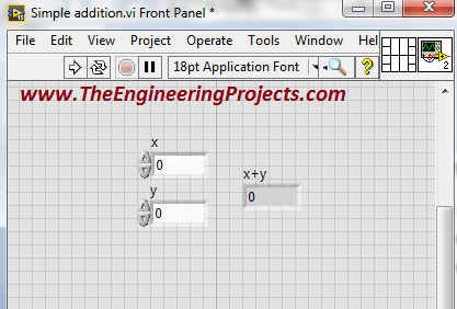
- Open the “Front Panel” window and it will be something like the image shown below:
- On the left side of the “Add” block there are two inputs represented by as “x” and “y”.
- And on the right side there is a single output represented by “x+y” to perform the addition operation.
- Now adjust the both of the input parameters to obtain the desired output according to the adjusted parameters.
- Here I have adjusted “x” input by assigning it with a value “2”.
- And I have adjusted “y” input by assigning it with a value “5”.
- You can see both of the adjusted inputs in the figure below:
How to Run LabView Simulation ???
- You have to see the output of the program according to the adjusted parameter
- Go to the “Run” button on the top left corner of the “Front Panel” window, and just run the program
- The figure shown below will explain a bit about both of the above two steps
- You can see the output of the program has been successfully obtained according to the adjusted input parameters.
- So that is how you can perform the simple addition of the two parameters in LabVIEW.
- You can also use the all of the other operators in the Functions-> Programming-> Numeric similarly to perform different operations for the different input parameters according to your own requirements.
For Loop using LabView Programming
- In previous part, you can see that as you compile (run) your program it shows the desired output and then terminates.
- That means if you have to change input parameters then you have to run your program again as well.
- Now I am going to explain you that what to do with this program, if you want that this should run for a number of iterations.
- There is “For Loop” option which helps us to run our designed algorithm for number of iterations we want.
- You can select the “For Loop” by following the below procedure:
- Select the “For Loop”, drag and place it in the “Block Diagram”.
- It will look like the figure shown below:
- You can see that there is a “N” symbol on the top left corner of the “For Loop”.
- Basically the symbol “N” shows the number of iterations for which we want to run our program.
- Go to the input terminal of the symbol “N” and click on it.
- Now, go to Create Constant as shown below:
- So, set the number of iterations according to the requirement.
- Here, I am going to set the iterations value to 5 as shown in below figure:
- Now place the designed algorithm inside the “For Loop” to run the program five times in this case as shown in the figure below:
- Now your program will run for five iterations.
While Loop using LabView Programming
- If you want that your program should have continue to run until you terminate then it is also possible.
- “While Loop” option will be helpful for us in such a condition.
- Here I will tell you how to select the “While Loop” in this software. It is quite similar to the selection of the “For Loop” described in previous section.
- Go to Functions-> Programming-> Structures-> While Loop as shown in below figure:
- Select the “While Loop” drag and place it on the “Block Diagram” window.
- Now, place the designed algorithm inside the “While Loop” like shown below:
- You can see there the “Run” button is not in a normal condition which shows that there is some problem with the program.
- It is due to the fact because we have not yet defined the terminating condition of the program.
- Now, go to the “Front Panel” window and right click on it.
- Go to Controls-> Modern-> Boolean-> Stop Button as shown in the figure below:
- Connect the “Stop Button” with the red dot surrounded with the green boundary at the bottom right corner of the “While Loop” as shown in the figure below:
- Now you can see that the “Run” button is now again in normal state which shows that the everything is going fine with the program.
- Now, run the program and it will continue to run until you press the “Stop Button” in the “Front Panel” window.
- Running Program is shown in the figure below:
- You can change the input according to the requirements and you can see output immediately and you do not have to run the program again and again for the different inputs
- If you press the stop button you can see that the program terminates only then
That's all from this tutorial. I hope you enjoyed that and it will help you in learning Labview Programming. If you face any sort of problem then you can ask us without feeling any kind of hesitation. I will explain the further details of NI LabVIEW in the later tutorials. Take care till then :)
Introduction to LabVIEW
Hello everyone. I hope you all will be absolutely fine. Today, I am going to share an Introduction to LabView. LabView is a really exciting software and recently I have worked on many LabView Project so I thought to start this new set of series in which I am gonna explain all about LabView from beginners level to Pro Level. So, today I am gonna upload the first tutorial in this LabVIEW series so that's why I have named it Introduction to LabView and I hope you are gonna like this tutorial. :)
LabVIEW basically stands for “Laboratory Virtual Instrument Engineering Workbench”. This software is designed by the National Instruments (NI) for the control and design of the projects. You can use it for simulation purposes, can also interface hardware with LabVIEW, data acquisition is another big benefit of LabView. Moreover we can also design automation and robotics projects in LabVIEW. Before designing such projects, let's first have a look at the Introduction to LabVIEW:
Introduction to LabVIEW
- So, let's get started with Introduction to LabView and first of all what you need to do is to open the NI LabVIEW 2015 software.
- A small window will open up as shown in the below figure:
- So, this newly opened LabView window will have two portions “left bar” and “right bar”.
- If you want to design new project then you have to click on the button “Create Project”.
- If you want to open the project which already exists then press “Open Existing” button.
Opening New VI in LabView
- Go to the “File” menu of the software as show in the figure below
- Click on “New VI” or you can press the short code Ctrl+N. to open up new VI in LabView.
- So, now when you click on this NewVI then you will see that two windows will open up.
- One of them is known as “Front Panel” and second is known as “Block Diagram”.
- Both windows and their functionalities are explained in detail below:
Block Diagram
- Here is the screen shot of the “Block Diagram” so when we are having the Introduction to LabVIEW then we must discuss these windows in detail. :)
- This window is named as Block Diagram because we design our LabVIEW Block Diagram in this window.
- It's more of a back end programming section.
- So suppose you are designing some simulation in LabView then what features you want in your simulation depends on your code in the Block Diagram.
Front Panel
- Here's the screen shot of “Front Panel” of LabVIEW.
- It's also known as GUI of LabVIEW.
- In this Front Panel of LabView, we design the presentable output.
- For example, you are working on some simulation and you have to display some sensors' values then they are gonna be displayed in this Front Panel.
So, both of these windows are equally important and works simultaneously with each other. So, if you change anything in Front Panel then its counter part in Block Diagram will also change. So, let's have a look at How to align these two windows in LabVIEW.
Windows Alignment in LabView
- Now we know that if we are gonna work on some LabView simulation then we have to deal with two windows and in the above section of Introduction to LabView, we have discussed both of these windows.
- Now the problem is when we are working on two windows simultaneously then we need both of them to be rite in front of us.
- In order to do so, press “Ctrl+T” and both of your windows will be rite in front of you.
- It will help you to align both the windows, the “Front Panel” and the “Block Diagram”.
- The aligned windows are shown below and you can see the are looking nice comparatively.
- If “Front Panel is there on you screen and “Block Diagram” window is not on the screen, then just pres “Ctrl+E”.
- You can see “Block Diagram” also appears automatically on the screen.
- You can perform it for the vice versa purpose as well.
Description of Block Diagram Window
- Block diagram is a window in which we can create our logic by using different blocks.
- NI LabVIEW basically supports Field Programmable Gate Array Language (FPGA).
- We have to select different blocks according to the requirement ad they are known as FPGA blocks.
- Press “Right Click” on the “Front Panel” a new “Function” tab opens as shown below:
- From this “Function Tab” you can select different blocks to create your logic according to the requirements
- The detail about few of the blocks and functions is given below.
Numeric Toolbox in LabVIEW
- Go to the Functions-> Programming-> Numeric and you will get all your numeric tools there.
- You can see, the following window on your screen
- You can see different alphanumeric blocks (operators) like addition, subtraction etc. in the above figure
- Using these operators you can perform different mathematical operations
Graphics in NI LabVIEW
- Graphics tool is another amazing tool in this software and I think we should discuss them in this Introduction to LabView.
- Go to Functions-> Programming-> Graphics & Sounds and you will get all your graphics tools in there.
- You can see a window on your screen as shown below:
- You can make three dimensional picture and plot three dimensional graphs as well.
Comparator in LabView
- Go to Functions-> Programming-> Comparison and there's a big list of comparator waiting for you there.
- You can see a window on the screen as shown below
- These blocks are used for the comparison of two or more than two operators.
- These blocks are used in the projects where there are some restrictions i.e. if temperature exceeds the threshold, fire alarm or buzzer turns into “ON” state then.
Loops in LabView
- Go to Functions-> Programming-> Structures and here lie the most important functions of LabView programming.
- The below window will appear on the screen:
- If you want to run your created logic for different no of iterations, these loops will be helpful.
- You have to just set the number of iterations and your program will according to the adjusted number of iterations.
Timing Toolbox in LabVIEW
- Go to the Functions-> Programming-> Timing and you will find all the timing blocks in there.
- You can see the following window on the screen:
- If you want that your program should run with some delay.
- These timing clock bocks will be helpful.
- Usually their values are in milliseconds but you can adjust them accordingly by setting their properties.
Driver Support in NI LabVIEW
- One of the amazing functions of the NI LabVIEW is that, it supports the external device drivers.
- The device which we want to use and interface with the NI LabVIEW, we have to just install the driver of that device.
- After the successful installation you can see that device in "Functions" Palette.
- For example, go to the Functions-> Programming at the end of the window you can see the installed drivers or toolkits.
- I have installed Arduino interface for NI LabVIEW 2015.
- The figure below describes all of the above steps.
NI LabVIEW Supported Devices
Here's the list of most commonly used NI LabVIEW devices:
- compactRIO.
- myRIO (Re-configureable Input Output Device).
- sbRIO (Single Board Reconfigureable Input Output Device).
- Arduino.
- Raspberry PI.
- NI LabVIEW suppors different devices.
- You have to just install the drivers or toolkit of these devices.
- After successful installation you will be able to use these devices.
Description of Front Panel
- Press “Right Click” on the “Front Panel” window
- You can see the output of your designed algorithm on the “Front Panel” window.
- We can make our output’s look more and more beautiful.
- For this purpose NI LabVIEW provides us with the “Decorations” section.
- Go to the Controls-> Modern-> Decorations and the following window will be appeared on your screen.
- These blocks are helpful while giving the better external look to the Front Panel.
- Now go to the Controls-> Modern-> Boolean and you will have a look at the Boolean Buttons which are different in shapes and sizes.
- You can see a new window on the screen as shown in below figure:
- Round LED, Square LED are used for some indication purposes.
- You can use a “Stop” button to terminate the program.
- You can use radio buttons for “checking” and un-checking purposes.
Graphical Visual Display
- Graphical Visual display is also a good function in NI LabVIEW.
- You can display your output on different graphs.
- Go to Controls-> Modern-> Graph and all the graphical Visual Displays open up.
- The figure shown below will be appeared on the screen.
- Select the graph you want and display your output on a particular graph.
- 3D graphs is a very good option for the good looking output.
Searching Desired Blocks
- Press “Right Click” in the front panel
- Go to the “Search” option as shown in the figure below
- Press the “Search” option
- You can see following window on the screen
- Type the name of the block you want to find.
- Sometimes the “simple search” method takes a lot of time in finding the desired blocks.
- So, I prefer to use the quick search method.
- So, you should use “Quick Search” method, it will be helpful in time saving perspective.
- Go to the “Front Panel” and press “Ctrl+Space Bar”.
- You can see a new window on the screen.
- You can see the window in the figure below.
- For example, I want to search the “Simulate Signal” block.
- So, I typed “Simulate Signal” in the search bar.
- The desired blocks are appeared as shown in the figure below.
So, that's all form today's tutorial on
Introduction to LabView. I hope that it will be helpful for all of you. I have tried my level best to share in detail, my knowledge on Introduction to LabVIEW, with all of guys. I'll share further knowledge about this software soon, till then take care :)
Eye Ball Detection in MATLAB
Buy This Project
Hello friends, I hope you all are doing great. In today's tutorial, I am going to share
Eye Ball Detection in MATLAB. I have designed this simulation in MATLAB and I have designed a GUI in which I am detection the Eye Balls from Images. Our team has worked quite hard in designing this project so we haven't shared the code for free. Instead we have placed a very small amount and you can buy it from our shop via PayPal. Click the above button in order to buy the project.
If you are having any difficulty in buying this project then you can also ask in comments and we will surely help you out. Moreover, this algorithm has a small restriction that the person's eyes must be open in the image and his/her eye balls must be clearly visible otherwise this algo won't work on it. I have added 10 images in the database which will help you in understanding the main algorithm of this project. So, let's get started with Eye Ball Detection in MATLAB:
Eye Ball Detection in MATLAB
- So, first of all, click the below button in order to buy this Eye Ball Detection Project in MATLAB.
Buy This Simulation
- Once you download the files, then open the files named as MainGUI.m.
- Note, you must have MATLAB 2015 or higher in order to run this program correctly.
- It will open up a window which will look something as shown in below figure:
- One thing you should remember that MATLAB is not much good with graphics so you may have to change your axes' sizes.
- Anyways now click the button which says Browse and open any of the images present in the folder and then click Load Image button.
- I have opened the below image:
- If everything goes fine then you will get results something as shown in below figure:
- So, you can see in the above figure that I have labelled all the images of Eye Ball Detection in MATLAB.
- These labels are actually the steps in which we are doing our Eye Ball Detection.
- So, first of all I cropped the Pair of eyes and shown it in the Figure 2.
- After that I gray scaled the image and it is shown in Figure3.
- Next thing we need to do is to crop single eye from the pair of eyes which is done in Figure 4.
- In Figure 5, I have simply converted my gray scale image into binary image.
- In Figure 6, I have applied some filters to make it more smooth and to ignore noises.
- In Figure 7, I have taken the inverse of image in Figure 6. That's why now Eye Ball is showing in white color and rest of the background is in black.
- In Figure 8 and 9, I have applied filters, filters are always used to remove noise and to make figure more visible.
- In figure 10, I have taken the edges of the previous image.
- Finally in Figure 11, I have detected the circular region and then plotted a circle around it and I have done the same thing in Figure 12.
- Here's the results of another image for Eye Ball Detection in MATLAB:
- As, I have told earlier that our team has done a lot of effort in designing this project that's why we haven't shared its code but you can buy it quite easily from our shop by clicking the above button.
- Moreover, I have designed this video which will help you better in understanding this project.
- So, please must watch this video before buying this simulation so that you are sure what you are buying. you can also contact us if you are having any problems in buying it.
- Here's the video for EyeBall Detection in Matlab:
So, that's all about
Eye Ball Detection in MATLAB. I hope you guys have enjoyed today's post. Will meet you guys in the next tutorial. Till then take care and have fun !!! :)
Interfacing of Keypad with PIC Microcontroller
Hello everyone, I hope you all are doing great. Today, I am going to share a very basic tutorial on PIC Microcontroller, which is Interfacing of Keypad with PIC Microcontroller. I have designed this simulation of Keypad with PIC Microcontroller in Proteus ISIS and the simulation along with code is given below for download. But I would suggest you to read it first and then design it on your own so that you learn most out of it.
In today's tutorial, I am not gonna discuss the details of How keypad works because I have discussed it in detail in my old tutorial
Interfacing of Keypad with Arduino so if you don't have much idea about working of keypad then I would recommend you to read that tutorial first, before proceeding with today's tutorial. I have also interface this Keypad with 8051 Microcontroller, so today we are gonna interface this keypad with PIC Microcontroller. I have written programming code for this project in MikroC Pro For PIC. So, let's get started with Interfacing of Keypad with PIC Microcontroller:
Interfacing of Keypad with PIC Microcontroller
- First of all, you can download the Simulation for this project along with programming code by clicking the below button:
Download Code & Simulation
- Now, let's design it step by step.
- I have used LCD Library for Proteus so download it first and then run this simulation.
- First of all, design a simple simulation in Proteus software as shown in below figure:
- Now paste the below programming code in MikroC Pro For PIC.
- In this Programming code, the key pressed on keypad will be displayed on the LCD.
- So, when you press any button on the keypad, it will appear on the LCD.
- Here's the code which you need to use in MikroC Pro For PIC:
unsigned short kp, cnt, oldstate = 0;
char txt[6];

char  keypadPort at PORTD;

sbit LCD_RS at RB0_bit;
sbit LCD_EN at RB1_bit;
sbit LCD_D4 at RB2_bit;
sbit LCD_D5 at RB3_bit;
sbit LCD_D6 at RB4_bit;
sbit LCD_D7 at RB5_bit;

sbit LCD_RS_Direction at TRISB0_bit;
sbit LCD_EN_Direction at TRISB1_bit;
sbit LCD_D4_Direction at TRISB2_bit;
sbit LCD_D5_Direction at TRISB3_bit;
sbit LCD_D6_Direction at TRISB4_bit;
sbit LCD_D7_Direction at TRISB5_bit;


void main() {
  cnt = 0;
  Keypad_Init();
  Lcd_Init();
  Lcd_Cmd(_LCD_CLEAR);
  Lcd_Cmd(_LCD_CURSOR_OFF);
  Lcd_Out(3, 2, "The Engineering");
  Lcd_Out(4, 5, "Projects");
   Lcd_Out(1, 1, "Key Pressed:");

  do {
    kp = 0;
    do
      kp = Keypad_Key_Click();
    while (!kp);

    switch (kp) {
      case 10: kp = 42; break;  // '*'
      case 11: kp = 48; break;  // '0'
      case 12: kp = 35; break;  // '#'
      case  1: kp = 49; break; // 1
      case  2: kp = 50; break; // 2
      case  3: kp = 51; break; // 3
      case  4: kp = 65; break; // A
      case  5: kp = 52; break; // 4
      case  6: kp = 53; break; // 5
      case  7: kp = 54; break; // 6
      case  8: kp = 66; break; // B
      case  9: kp = 55; break; // 7
      case 10: kp = 56; break; // 8
      case 11: kp = 57; break; // 9
      case 12: kp = 67; break; // C
      case 13: kp = 42; break; // *
      case 14: kp = 48; break; // 0
      case 15: kp = 35; break; // #
      case 16: kp = 68; break; // D

    }

    Lcd_Chr(1, 14, kp);
  } while (1);
}
- Now get your hex file and upload it in your Proteus Simulation.
- Run your simulation and if everything goes fine then you will get results as shown in below figure:
- So, in the above figure, I have pressed button 5 on the keypad and it is shown on the LCD.
- Here's the video demonstration which will help you better in understanding this project:
So, that's how we can interface our Keypad with PIC Microcontroller. If you got into any trouble following this tutorial then ask your problems in the comments and I will help you out. That's all for today, I hope you guys can now interface keypad with PIC Microcontroller easily. :)
Interfacing of Arduino with GLCD
Hello friends, I hope you all are doing great and having fun with your lives. In today's tutorial, I am going to share How to interface Arduino with GLCD. I am gonna design a Proteus Simulation in which I will interface Arduino GLCD together. GLCD is also called Graphical LCD so today we are gonna do some designing on the LCD. The GLCD I am going to use is ks0108 and its model in Proteus is LGM12641BS1R and I have shared the complete Simulation along with Arduino Code below for download. But I would suggest you to design it on your own so that you could get the most out of it. If you haven't worked on the LCD before then I would suggest you to read
How to Interface Simple LCD with Arduino.
Moreover, I am quite happy to announce that we have started
TEP Forum so if you guys have any questions related to your engineering projects then ask in our forum and we will try our best to resolve your issues. Anyways, let's get back to our today's tutorial and interface Arduino GLCD in Proteus ISIS.
Interfacing of Arduino with GLCD
- First of all, you can download the Proteus Simulation and Arduino Code for Interfacing of Arduino with GLCD, by clicking the below button:
Download Code & Simulation
- Now let's design it so that you can understand how this is working.
- So, first of all design a Proteus Simulation for Interfacing of Arduino with GLCD, as shown in below figure:
Note:
Proteus doesn't have Arduino in its database so you need to install this
Arduino Library for Proteus if you wanna use Arduino in Proteus.
- Now upload the below Arduino code in your Arduino Software and Get your Arduino Hex File, which we are gonna upload in our Proteus Arduino.
- Here's the Arduino Code for Interfacing of Arduino with GLCD:
Note:
- You also have to install the GLCD Library for Arduino, I have added this library in the above package so when you download it first of all install this library in Arduino Software.
#include <glcd.h>
#include "fonts/allFonts.h"
#include "bitmaps/allBitmaps.h"

Image_t icon;

gText textArea;
gText textAreaArray[3];
gText countdownArea =  gText(GLCD.CenterX, GLCD.CenterY, 1, 1, Arial_14);

unsigned long startMillis;
unsigned int  loops = 0;
unsigned int  iter = 0;
         int  theDelay = 20;

void setup()
{
  GLCD.Init();
  if(GLCD.Height >= 64)
    icon = ArduinoIcon64x64;
  else
    icon = ArduinoIcon64x32;

  GLCD.ClearScreen();

  GLCD.SelectFont(System5x7, BLACK);
  GLCD.CursorTo(2, 2);
  GLCD.print("The Engineering");
  GLCD.CursorTo(5, 3);
  GLCD.print("Projects");
}


void  loop()
{

}
- So, now if everything goes fine then when you run your Proteus Simulation of Arduino with GLCD, you will get results as shown in below figure:
- So, what we have done is we just printed our blog name on the GLCD using Arduino.
- Now, in the package you download I have also added another example which when you upload will give you a demo of GLCD.
- Here's the results of the second example, I have added some screenshots:
- So, that's how you can interface Arduino with GLCD and can design anything you want.
- It's really very easy but quite lengthy, I must tell.
- I have designed this video which will help you in better understanding:
So, that's all about Interfacing of Arduino with GLCD and I hope I have helped you guys in some ways. So, will meet you guys in the next tutorial. Till then take care and have fun !!! :)
How to use Arduino PWM Pins
Hello friends, I hope you all are doing great. In today's tutorial, I am going to show you
How to use Arduino PWM Pins. It's the next tutorial in our new
Arduino Tutorial for Beginners series. We will design a small code in which we will be controlling a dc motor's speed using the Arduino PWM Pins but before going into the details, let me first give you an introduction to Arduino PWM Pins because without understanding the PWM, which is the abbreviation of
Pulse Width Modulation, you won't be able to understand How to use Arduino PWM Pins. In our previous tutorial, we have seen
How to use analogWrite in Arduino and I have told you in that tutorial that we use this command for PWM as well. So, today we will have a look at How to do that.
PWM is an abbreviation of Pulse Width Modulation, its a simple technique in which we just modulate the width of a pulse to get our required results. Suppose, we have a 12V DC signal but my requirement is to get the 6V instetad of 12V so here what I need is PWM. I will use PWM on 12V signal and then reduce it to 6V. Another important thing related to PWM is duty cycle. Duty Cycle is the percentage for which the pulse remains HIGH. For example, if the pulse is of 12V and you turn it into 6V using PWM then the duty cycle of PWM is 50%. I have posted many tutorials on PWM for example you should have a look at
How to Generate PWM in 8051 Microcontroller. In this tutorial, I have explained in detail about PWM signal. Moreover, you can also have a look at
DC Motor Speed Control using Arduino in which I have controlled the speed of DC Motor with LDR Sensor. Anyways, let's get back to How to use Arduino PWM Pins:
How to use Arduino PWM Pins ???
- You can download the complete simulation along with its Arduino code for Arduino PWM by clicking the below button:
Download Simulation & Cod
- First of alll, we should know which pins of Arduino can be used for PWM purposes.
- So, if you have a look at the below figure, its an Arduino UNO and all the pins of Arduino UNO which has this sign "~" in front of them are PWM pins.
- If you have a look at the above Arduino UNO image then you can see that "~" this sign is placed in front of six pins.
- So, Arduino UNO PWM Pins are:
- Pin # 3
- Pin # 5
- Pin # 6
- Pin # 9
- Pin # 10
- Pin # 11
- Using these PWM Pins, you can create the PWM pulse which we are gonna do rite now. :)
- So, design a simulation in Proteus as shown in the below figure:
- As you can see in the above figure that I have used LDR Sensor with Arduino UNO and I have plotted the PWM output coming from Arduino UNO on the oscilloscope.
- For PWM output the command used in Arduino is:
analogWrite(PWM_Pin, PWM_Value);
- As, you can see its just an analog Write command and using it you can write any value to the PWM Pin ranging from 0 to 255.
- At 0 the duty cycle of PWM will be 0% and at 255 it will be 100%.
- So, what I did in the above example is I just take the analog value coming from LDR and then transferred it to PWM Pin of Arduino UNO.
- So, now upload the below code in your Arduino board:
int PWMControl= 6;
int PWM_Input = A0;

int PWM_Value = 0;

void setup() {
    pinMode(PWMControl, OUTPUT);
    pinMode(PWM_Input, INPUT);
    Serial.begin(9600);
}

void loop()
{
    PWM_Value = analogRead(PWM_Input);
    PWM_Value = map(PWM_Value, 0, 1023, 0, 255);
    analogWrite(PWMControl, PWM_Value);
}
- So, now Get your Arduino Hex File and upload it in your Proteus software.
- You will also need to download Arduino Library for Proteus, if you wanna use this Arduino UNO in Proteus.
- Now, if everything goes fine then you will get results as shown in below figure:
- Now you can see in the above figure that I have shown the PWM pulse in the oscilloscope and now when you change the LDR value then this pulse's PWM will also change.
- You can download the complete simulation with Arduino code by clicking the button above.
- If you have any problems or issues in this Arduino PWM tutorial then let me know in comments.
I hope you have enjoyed today's post on Arduino PWM Pins and I would suggest you to have a look at
DC Motor Speed Control using Arduino, it will help you a lot in understanding the basic concept of Arduino PWM. So, that's all about Arduino PWM, will see you guys in the next tutorial. Till then take care and have fun !!! :)
Arduino Tutorial for Beginners
Hello friends, I hope you all are fine and having fun with your lives. Today, I am going to share a complete
Arduino Tutorial for Beginners because I was having a lot of requests about it. Reader were asking the same question that they are new to Arduino and how should they start so if you are beginner to Arduino and you don't have any idea How to learn it then you should read the below tutorials.
I have posted all the basic Arduino Tutorial for Beginners already so in today's tutorial I am just gonna arrange them and must ask you to read them one by one from top to bottom and at then end you will really be able to design any kind of project on Arduino. So, let's get started with Arduino Tutorial for Beginners:
Arduino Tutorial for Beginners
Before going into the practical Arduino Programming, you must first read some theoretical knowledge about Arduino which will really help you out in your Arduino Projects. So these are the
basic Arduino tutorial which I will post here step by step:
What is Arduino ?
First of all, you should read this tutorial in which I have given the basic introduction of Arduino. This tutorial is essential one, if you are new to Arduino.
Arduino Vs Raspberry Pi
Next thing you should read is Arduino Vs Raspberry Pi, its not that important but its always good to have a look at alternatives.
Installation of Arduino Driver in Windows
Now, I suppose that you know the basics of Arduino and have got your Arduino UNO in your hand and are ready to install Arduino Drivers in your Windows.
Arduino Library for Proteus
Next thing you need to read is How to use Arduino Library for Proteus. Using this library you can easily simulate your Arduino boards in Proteus software.
Getting Started with Arduino Software
Now you have the basic idea of Arduino board and you know How to use it in Proteus, the next thing you need to do is to have some understanding about Arduino software.
Basic Arduino Commands
Now, that you have understood the basics of Arduino and its programming so now let's have a look at some
Basic Arduino Commands and I would suggest you to test these commands in Proteus on your own so that you do mistakes and get some knowledge from them. Anyways, let's continue with these Basic Arduino Commands:
Getting Started with Arduino Programming
After having a look at the Arduino software, next thing you need to do is to read about Getting Started with Arduino Programming.
Arduino Data Types
Then we have a tutorial at Arduino Data Types in which we have explained in detail all the Data Types of Arduino.
How to use pinMode in Arduino
How to use pinMode in Arduino is the next tutorial which you must read so that you have an idea about how to make pins input or output.
How to use DigitalRead in Arduino
How to use DigitalRead in Arduino is the next tutorial which you must read so that you have an idea about how to use the digital Pins of Arduino.
How to use DigitalWrite in Arduino
How to use DigitalWrite in Arduino is the next tutorial which you must read so that you have an idea about how to use the digital Pins of Arduino.
How to use AnalogRead in Arduino
How to use AnalogRead in Arduino is the next tutorial and I have explained here how to read the status of analog Pins.
How to use AnalogWrite in Arduino
Analog Write is used to update the status of analog Pins as well as PWM Pins. Here we will discuss this command and in next tutorial we will have a look at PWM Pins.
How to use Arduino PWM Pins
How to use DigitalRead in Arduino is the next tutorial which you must read so that you have an idea about how to use the digital Pins of Arduino.
A Simple Arduino LED Example
First of all, you should have a look at A Simple Arduino LED Example in which I have designed a simple example in Proteus and blinked the LED at Pin # 13 of Arduino.
How to write Arduino code
Next article you should have a look at is How to write Arduino code, in this tutorial I have explained how to write arduino code efficiently.
- Now that you have the idea of basic Arduino programming so now let's move a little further and have a look at How to do Arduino Serial Communication. I have posted a lot of Arduino Serial Tutorial and I would suggest you to read them one by one. Here are all the links of Arduino Serial Tutorials:
At the end, I would suggest you to have a look at this list of
Arduino Projects in which I have given all the Arduino Projects which are posted on our blog, so once you get trained in Arduino then you can try those projects and can get pro in Arduino.
The Practical Guide for Tech Entrepreneurs
Even the best tech entrepreneurs have made mistakes while working their way to the top. Many of the past and present entrepreneurs have difficulty making their businesses succeed. It is a rough world for beginners. It is hard to succeed when a person does not know how to grow their business and make a financial gain. The Practical Guide for Entrepreneurs has been written to assist other entrepreneurs. It teaches the steps of what to do and what not to do as a beginner. The guide answers a lot of questions that tech startup has. They are informative and knowledgeable in the steps to take to make a business excel. The valuable information can impact their tech business and help it financially grow into something bigger. The entrepreneur guide has important information that should be followed and examples of decisions to stay away from.
Start at The Beginning
A tech entrepreneur should start with getting your office or space ready to conduct business. Get the area ready and supplies set up for a tech business. It is very important to always find ways to lessen your business cost. From office supplies to technology, find discount deals from different shops that offer promo codes such as Currys and Sprint. Also, find team members who want to work with you. If you need other items such as the internet, then this would be the time to purchase them. It is important to be prepared and educated on what to expect next. The guide explains these and many other pieces of information about how to begin as a tech entrepreneur.
Capital Gain and Finances
The Practical Guide for Tech Entrepreneurs discusses how to get financial assistance and capital gain. Financial stability is important to understand for a tech startup. A business that has money to create more business, is a surviving company. There are businesses that had begun as tech entrepreneurs. These companies have risen above and created a huge name for themselves.
Knowledge of Surroundings
A tech entrepreneur needs to know the surroundings. Being able to recognize bad deals is important. It is a good idea to say no to a bad investment or proposition. If you feel that your surroundings are not improving, then it is time to get out. If at some point, you need to get out from under the company, then it is best to take the time to do some research. Find out who would be the best buyer and ensure that the team is taken care of. The guide explains how to make a decision that works well for everyone involved.
Lead by Example
A tech entrepreneur can review the companies that have succeeded and grown their companies and brands. These companies are great resources. The entrepreneurs can learn and study the way these companies had conducted business and overcome the challenges to excel in the industry.
A tech entrepreneur will benefit from the guide because of the valuable and educational information. There are many wonderful tips and suggestions to help people in the tech world to succeed. It also teaches the mistakes to avoid and ways to improve from those bad choices.