

LCD is also used almost in every Engineering Project for displaying different values. For example, if you have used the ATM machine, which you must have, then you have seen an LCD there displaying the options to select. Obviously that's quite a big LCD but still LCD. Similarly, all mobile phones are also equipped with LCDs. The LCD we are gonna use in this project is quite small and basic. It is normally known as the 16x2 LCD as it has rows and 2 columns for writing purposes. So, we are gonna interface that LCD with 8051 Microcontroller. The proteus Simulation along with hex file and the programming code in keil uvision 3 is given at the end of this post for download. If you are working with Arduino, then you should have a look at Interfacing of LCD with Arduino. The next level from LCD is Graphical LCD also known as GLCD, so if you wanna know more about that then you should read Interfacing of Arduino with GLCD. So, let's get started with it.
Interfacing of LCD with 8051 Microcontroller in Proteus ISIS
- First of all, we are gonna need to design the Proteus Simulation as we always did.
- After designing the simulation, we are gonna write our embedded code for 8051 Microcontroller.
- I will be designing the code in Keil uvision3 compiler and the 8051 Microcontroller I am gonna use is AT89C51.
- So, let's first get started with Proteus Simulation for interfacing of LCD with 8051 Microcontroller.
Proteus Simulation
- First of all, get the below components from the Proteus components Library and place them in your workspace.

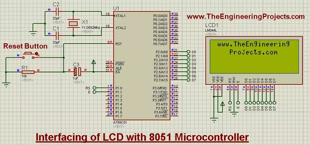
- Now design a circuit in Proteus using these above components as shown in below figure:
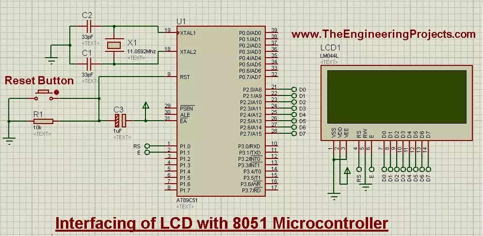
- If you have read the previous tutorial, you have noticed a small change, which is the RESET button.
- Its a good thing to have a RESET button in your project. When you press this button, your 8051 Microcontroller will get reset and will start again.
- Moreover, we have added a 20x4 LCD. The data pins of this LCD are attached with Port 2, while the RS and enable pins are connected to 0 and 1 pins of Port 1.
- So, now let's design the programming code for interfacing of LCD with 8051 Microcontroller.
Programming Code
- For programming code I have used Keil uvision 3 software. I am gonna first explain the code in bits so let's get started with it.
- Before starting the LCD programming, let me clear few basic concepts.
- In LCD, there are two types of data, we need to sent.
- The first type is the command like we need to tell the LCD either to start from first column or second column so we need to place the LCD cursor at some point from where we need to start writing. So, this type of data is called commands to LCD.
- The second type of data is the actual data we need to print on the LCD.
- So first of all we send commands to the LCD like the cursor should go to second line and then we send the actual data which will start printing at that point.
- The first function, I have used is named as lcdinit() , this function will initialize the LCD and will give the initializing commands to it.
void lcdinit(void)
{
    delay(15000);
   writecmd(0x30);
     delay(4500);
   writecmd(0x30);
     delay(300);
   writecmd(0x30);
     delay(650);

   writecmd(0x38);    //function set
   writecmd(0x0c);    //display on,cursor off,blink off
   writecmd(0x01);    //clear display
   writecmd(0x06);    //entry mode, set increment
}
- Now in this function I have used another function which is writcmd, which is as follows:
void writecmd(int z)
{
   RS = 0;             // => RS = 0
   P2 = z;             //Data transfer
   E  = 1;             // => E = 1
   delay(150);
   E  = 0;             // => E = 0
   delay(150);
}
- In order to send the commands to LCD with 8051 Microcontroller, we have to make the RS pin LOW and then we send the data and make the Enable pin HIGH to LOW which I have done in the above writecmd() function.
- Next function, we have used is writedata() function, which is as follows:
void writedata(char t)
{
   RS = 1;             // => RS = 1
   P2 = t;             //Data transfer
   E  = 1;             // => E = 1
   delay(150);
   E  = 0;             // => E = 0
   delay(150);
}
- So, if you check above two functions then its quite clear that when we send command to the LCD then we have to make RS pin 0 but when we need to send data to be printed on LCD then we need to make RS pin 1. That's the only thing worth understanding in interfacing of LCD with 8051 Microcontroller.
- Now below is the complete code for interfacing of LCD with 8051 Microcontroller and I think now you can get it quite easily.
#include<reg51.h>

//Function declarations
void cct_init(void);
void delay(int);
void lcdinit(void);
void writecmd(int);
void writedata(char);
void ReturnHome(void);

//*******************
//Pin description
/*
P2 is data bus
P1.0 is RS
P1.1 is E
*/
//********************

// Defines Pins
sbit RS = P1^0;
sbit E  = P1^1;

// ***********************************************************
// Main program
//
void main(void)
{
   cct_init();                                     //Make all ports zero

   lcdinit();                                      //Initilize LCD

   writecmd(0x81);
   writedata('w');                                 //write
   writedata('w');                                 //write
   writedata('w');                                 //write
   writedata('.');                                 //write
   writedata('T');                                 //write
   writedata('h');                                 //write
   writedata('e');                                 //write
   writedata('E');                                 //write
   writedata('n');                                 //write
   writedata('g');                                 //write
   writedata('i');                                 //write
   writedata('n');                                 //write
   writedata('e');                                 //write
   writedata('e');                                 //write
   writedata('r');                                 //write
   writedata('i');                                 //write
   writedata('n');                                 //write
   writedata('g');                                 //write

   writecmd(0xc4);

   writedata('P');                                 //write
   writedata('r');                                 //write
   writedata('o');                                 //write
   writedata('j');                                 //write
   writedata('e');                                 //write
   writedata('c');                                 //write
   writedata('t');                                 //write
   writedata('s');                                 //write
   writedata('.');                                 //write
   writedata('c');                                 //write
   writedata('o');                                 //write
   writedata('m');                                 //write

   ReturnHome();                                   //Return to 0 position

    while(1)
    {
    }

}


void cct_init(void)
{
P0 = 0x00;   //not used
P1 = 0x00;   //not used
P2 = 0x00;   //used as data port
P3 = 0x00;   //used for generating E and RS
}

void delay(int a)
{
   int i;
   for(i=0;i<a;i++);   //null statement
}

void writedata(char t)
{
   RS = 1;             // => RS = 1
   P2 = t;             //Data transfer
   E  = 1;             // => E = 1
   delay(150);
   E  = 0;             // => E = 0
   delay(150);
}


void writecmd(int z)
{
   RS = 0;             // => RS = 0
   P2 = z;             //Data transfer
   E  = 1;             // => E = 1
   delay(150);
   E  = 0;             // => E = 0
   delay(150);
}

void lcdinit(void)
{
    delay(15000);
   writecmd(0x30);
     delay(4500);
   writecmd(0x30);
     delay(300);
   writecmd(0x30);
     delay(650);

   writecmd(0x38);    //function set
   writecmd(0x0c);    //display on,cursor off,blink off
   writecmd(0x01);    //clear display
   writecmd(0x06);    //entry mode, set increment
}

void ReturnHome(void)     //Return to 0 location
{
  writecmd(0x02);
    delay(1500);
}
- So, place this code in your keil software and get the hex file.
- Upload this hex file in your Proteus software and Run it.
- If everything goes fine then you will get something as shown in below figure:
- Now, you can see we have printed our website address on the LCD with 8051 Microcontroller.
- You can print anything you wanna print on this LCD instead of our address.
- You can download the Proteus Simulation along with hex file and the programming code in keil uvision 3 by clicking on below button.
Download Proteus Simulation & Code
That's all for today, in the next post I am gonna share how to display custom characters on LCD with 8051 Microcontroller, because till now you can just display the simple characters like alphabets and numbers on it but can't display the custom characters like arrowhead etc. You should have a look at LCD Interfacing with Microcontrollers, where I have combined all tutorials related to LCD. So stay tuned and have fun.