- What is Pulse Width Modulation?
- What is 555 Timer?
- how does 555 Timer is used in the Pulse Width modulation circuit?
- How do we design the circuit of Pulse Width Modulation in Proteus ISIS?
| Where To Buy? | ||||
|---|---|---|---|---|
| No. | Components | Distributor | Link To Buy | |
| 1 | 555 Timer | Amazon | Buy Now | |
| 2 | LEDs | Amazon | Buy Now | |
| 3 | Resistor | Amazon | Buy Now | |
Pulse Width Modulation
Pulse width Modulation is a useful technique in the world of Modern Electronics. Let's have a look at the information about Pulse Width Modulation.Abbreviation of Pulse Width Modulation
The Abbreviation of the Pulse Width Modulation technique is PWM.Definition of Pulse Width Modulation
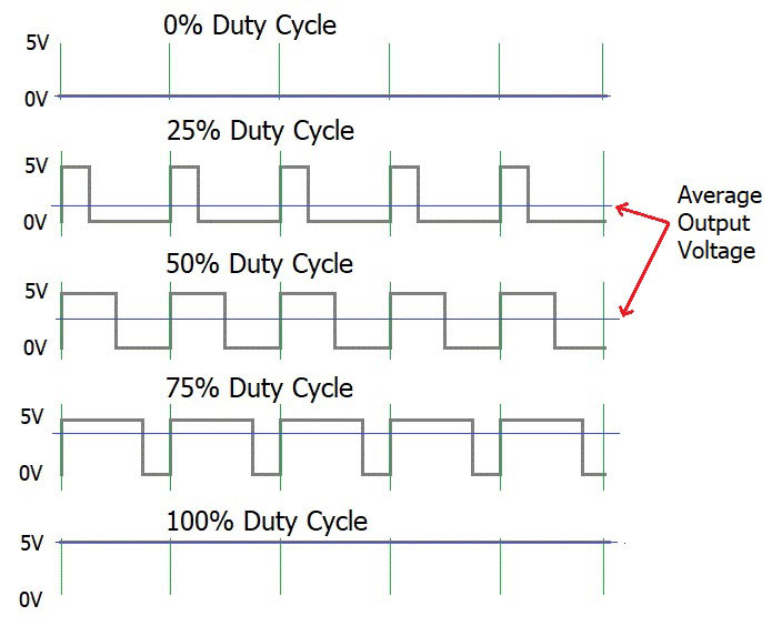
We define the pulse Width Modulation as:"The Pulse Width Modulation is the technique in the electronics to control the power given to the analogue devices through which the average power delivered by the electrical signal is reduced due to division of the signals into discrete parts."The Pulse Width Modulation is important to the inertial load devices such as motors because in these devices the change is slow due to their inertial ability and the Pulse Width Modulator has enough time to control the device.
Example of PWM
We know that in the bulb that we use in our daily life, the AC Power changes its direction from positive to negative cycle and vise versa. The frequency through which the cycle change decides the brightness of the bulb. Consider the example of the circuit in which the LED is connected to the power. The Power connection lightens the LED. When the switch between the power source and the bulb is close, the power is transmitted to the bulb and the brightness is observed.
DID YOU KNOW????????????
"The Pulse Width Modulation technique is also called as the Pulse Duration Modulation or PDM. It is because this technique works with the duration of the cycle of the circuit. "
555 Timer in Pulse Width Modulation
Prior to start the work of 555 Timer in Pulse Width Modulator, we must clear some important concepts about the 555 Timer device. Let's have a glance on the points.Definition of 555 Timer
The 555 Timer was termed as the SE NE555 Timers. Another Type of the 555 Timer is SE555 Timer. These were first invented by "Signetic Corporation" . We define the 555 Timer as:"The 555 Timer is an 8 pin Integrated Circuit that generates accurate timing pulse. The designing of the 555 timer is done by collectively arranging the electrical and electronic components such as resistors, transistors, diodes and Flip Flops."

Pin out of 555 Timer
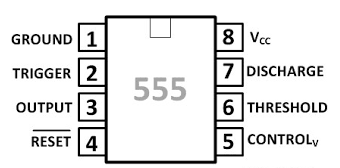
There are 8 pins of 555 Timer and each pin has its own function and operation. For the best concept, we have designed a table for each pin given below:| Pin Number | Pin Name | Description |
| 1 | Ground | This pin is labeled as GND and used to supply the 0 voltage. |
| 2 | Trigger | When the Time interval starts, the output remains low when this pin is high and vise versa. |
| 3 | Output | This is the output pin. |
| 4 | Reset | This pin overrides the Trigger pin and that overrides the Threshold. It is connected with Vcc if not used. |
| 5 | Control | It controls the Pulse Width and the level of threshold and Trigger. |
| 6 | Threshold | Hen the voltage is applied at this pin, it acts in the contrast to the voltage. |
| 7 | Discharge | This pin is an open-collector output. During the intervals, this pin is used to discharge the capacitor. |
| 8 | Supply | This is the power supply pin. The input of power is taken against the Ground pin. |
DID YOU KNWO???????????
"We use the counter instrument in the Proteus to count the Pulse Width Modulation of the circuit using 555 Timer."
Implementation of PWM using 555 Timer in Proteus ISIS
To implement the Pulse Width Modulation using 555 Timer, we are using the simulation in Proteus ISIS. To Implement the 555 Timer PWM just follow the simple steps given next:- Fire up your Proteus Software.
- Choose the following components:
- 555 Timer
- 1N4148 Diode
- 3005P-1-502 Variable Resistor
- DC Power Supply
- Resistor
- Counter
- Oscilloscope
- Fix first five components from the "Pick Library" at the working area.
- Change the values of Resistor, Capacitors and variable Resistors according to the table given below:
Component Values Resistor 1k ohm Variable Resistor 50k ohm Capacitor 1 10nf Capacitor? 1uF DC Power source 10V
- Go to Terminal mode>Ground and set it at the end of the circuit.
- Connect the components through the connecting wires according to the image given next:

- To get the counting of the output, go to virtual Instrument Mode and choose the counter.
- Go to Virtual instrument Mode and select the Oscilloscope.
- Connect the counter with any terminal of the Oscilloscope.
- Join both the instruments with pin 3 of 555 Timer.

- Pop the play button and simulate the circuit.
- Change the values of voltages and the frequency according to need.
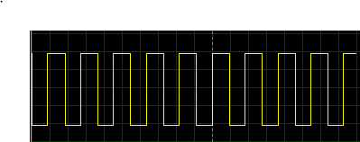
- We observe that the Oscilloscope shows us the width as:


