Creating the First Ladder Logic Program in PLC Simulator


After this article, you will have a complete understanding of PLC contact and coil including their types and possible causes. Because they are the building block of any rung of a ladder logic program. So let us start with ladder logic rung components.
Ladder Logic Contact/Input
- In ladder logic programming, a contact represents the input of the system and it could be a button press by the operator or a signal from the sensor.
- Examples of contacts are toggle switches, pushbuttons, limit switches, sensors like level, pressure, proximity switches et cetera.
- There are two types of contacts normally used, which are:
- Normally Open Contact.
- Normally Closed Contact.
1. Normally Open Contact
- A normally open contact is Open/LOW by default and it gets Closed/HIGH by pressing or getting signal from any external source i.e. sensors.
- As shown in the first row of figure 1, the contact is open or disconnected by default and then the operator turns it to closed or connected status, shown in the second row.
Figure 1: Normally Open (NO) contact [1]
- Let's understand it with its equivalent electrical circuit, imagine you wire a switch in series to a lamp as in figure 2.
- After you complete wiring and connect L1 to the hotline and L2 to the neutral.
- See that at the start the lamp is off until you come and press the pushbutton then it is turned on.
- So, here the switch is acting as a normally open switch.
Figure 2: Normally open contact or switch in a circuit [2]
2. Normally Closed Contact
- A normally closed contact is at HIGH/Closed state by default and gets Low/Open if pressed by the operator.
- Figure 3 shows the symbol of normally close contact.
- So it flows current at the very beginning and disconnects the current flow by being pressed by the operator to become like an open circuit or contact.
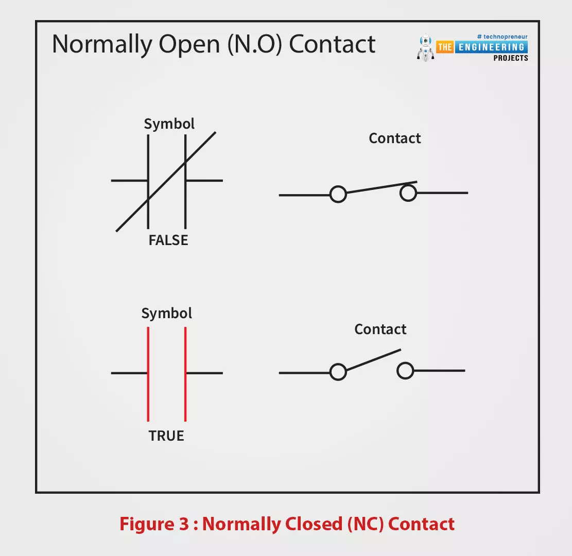
Figure 3: Normally Closed (NC) contact
- For elaborating the behavior, let us wire a circuit that is depicted in figure 4.
- The contact is connected in series with a lamp to convey the current and let it turn on.
- So initially, the lamp started in ON status when the contact is not activated by the user.
- And, when the operator activates the contact it turns off.
- So, the switch is acting as a normally closed switch.
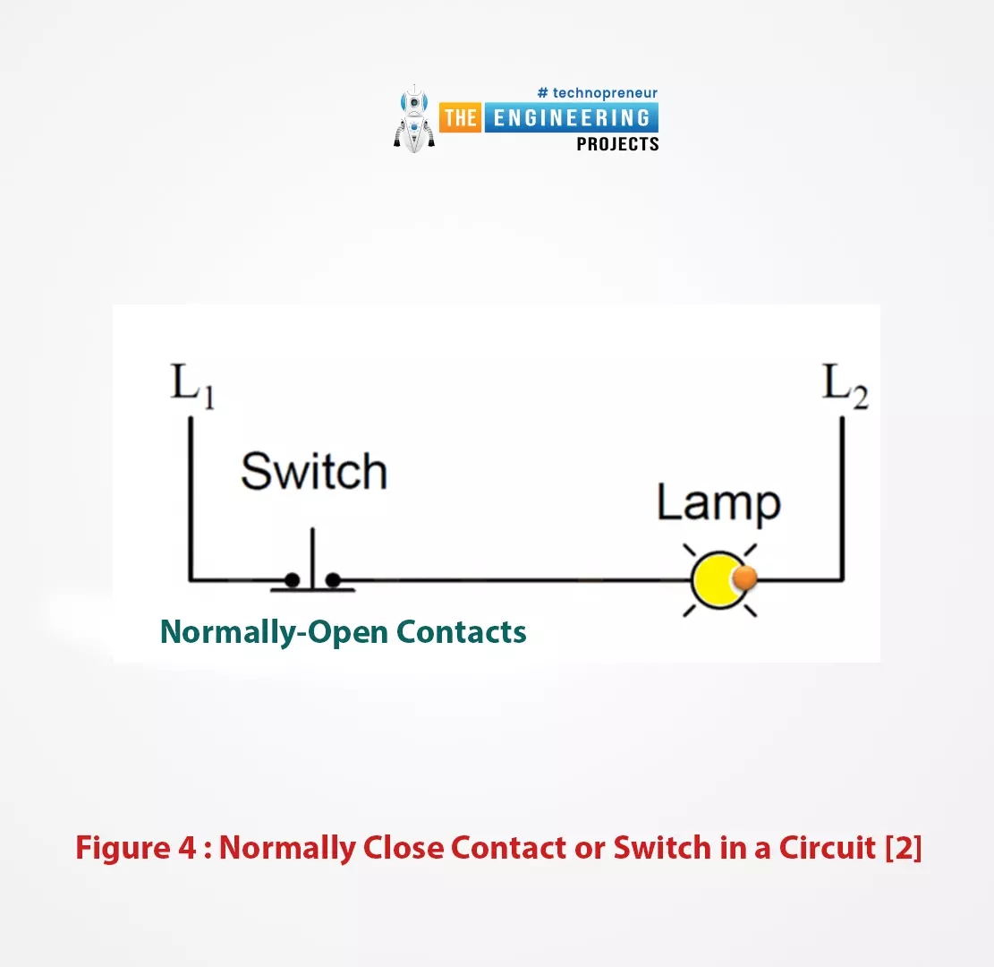
Figure 4: Normally close contact or switch in a circuit [2]
Ladder Logic Coil/Output
- The coil in ladder logic represents the actuator or the equipment we aim to turn on or off.
- A good example of a coil is a lamp and motor.
- Typically it is located at the most right side of the ladder logic rung.
- Same as contact has two types based on the initial state and the next state after user activation, also the coil comes in two forms which are:
- Normally Active Coil
- Normally Inactive Coil as shown in figure 5.
- An inactive coil is normally not energized until it gets connected by connecting the left side to the hot wire thanks to a contact.
- In contrast, active or negated coil type comes initially On status or energized and turned off when the left side is connected to the hot wire.
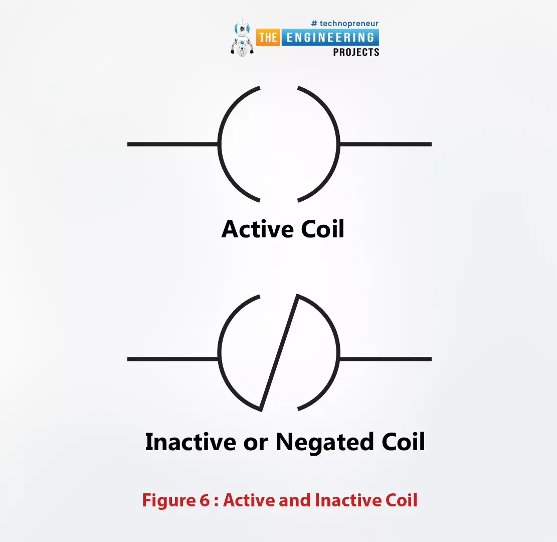
Figure 6: active and inactive coil
Create First Ladder Logic program
To our fortune we no longer need wires and devices to practice what we have been learning together, thanks to the simulator, which we have installed in the previous lecture. Let's create a new project on TIA portal software and test it with the PLCSIM simulator.
Creating a new project on TIA Portal
As this is the first time to use our software to write and simulate a ladder logic code, let us go step by step creating our very first project on the TIA portal software.
- You now get in the Lab by opening the TIA portal and hitting create a new project as shown in Figure 7.
- On the right, you just need to name your project like “new project” and you may leave the default location of projects or alter the data to the project file location as you prefer.
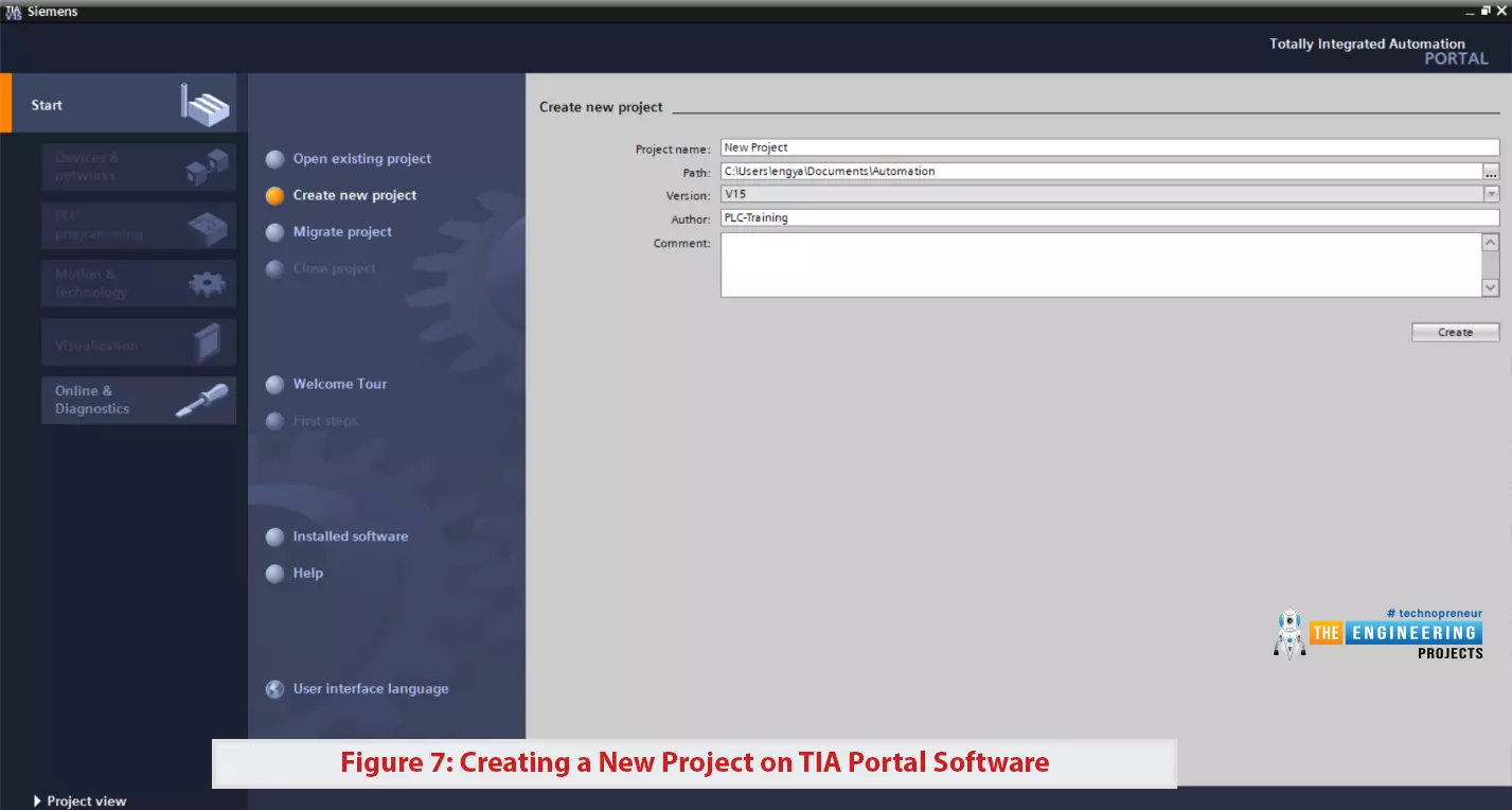
Figure 7: Creating a new project on TIA portal software
- You will have to select a PLC controller whom we are going to use. So you simply select one PLC controller as shown in figure 8 and click okay.
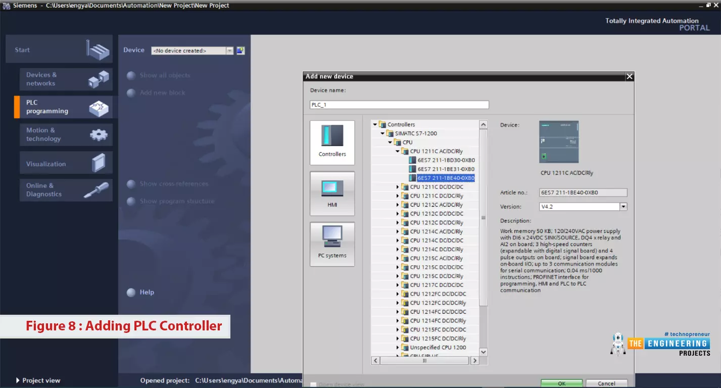
Figure 8: adding PLC controller
- The wizard now goes on asking you to add a program block.
- You can see in Figure 9, the default program block is the Main block which has the main program and other blocks are additional blocks.
- So for now let us go with the essential requirements for our program which is the main block and you just double click on the Main block to go to the next step.
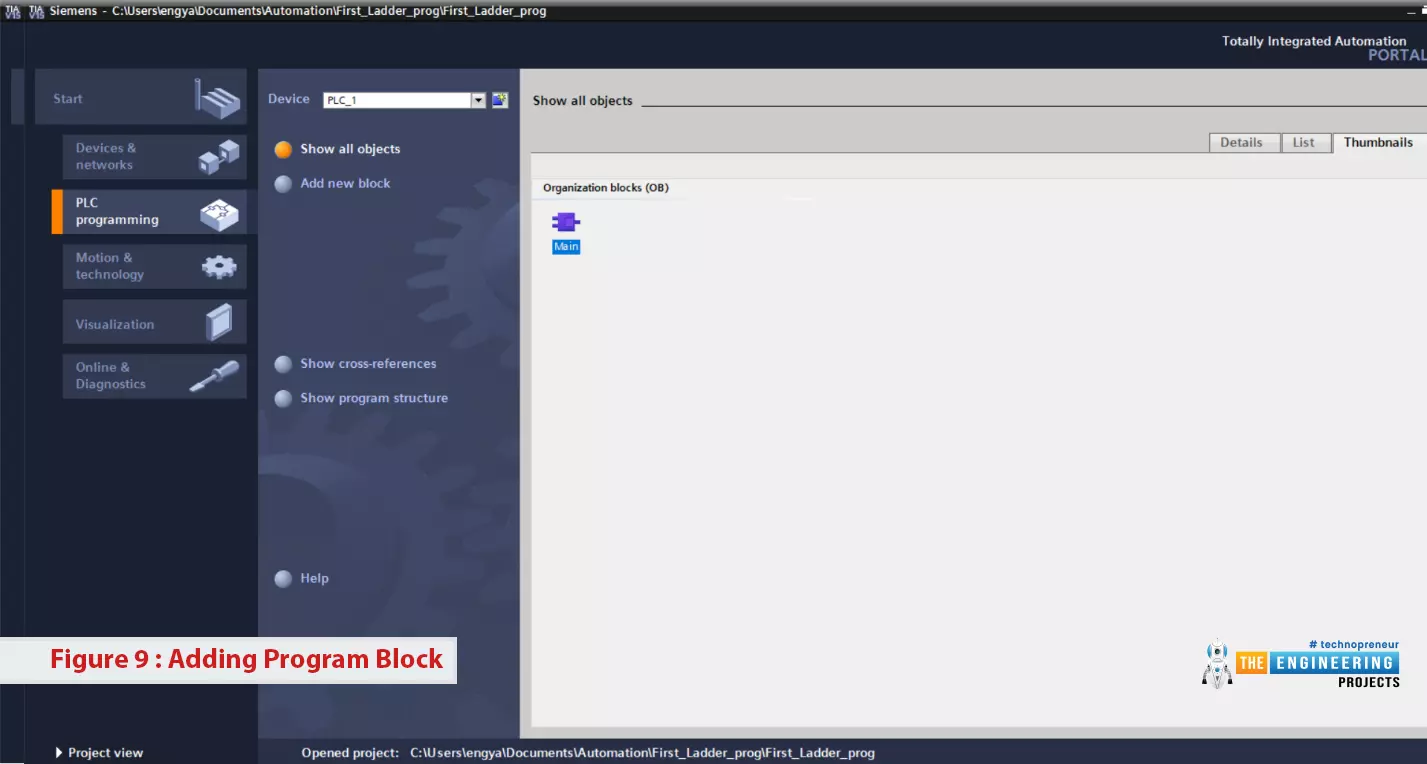
Figure 9: adding program block
I just want to say well done! And congratulate you that you are now all set to start writing your first ladder logic rung as shown in Figure 10. It shows on the left the project components including hardware i.e. devices and controllers, networking devices, configurations, program blocks etc. The most important thing you need to know for now is the program blocks which contain the only main block and other blocks as the project needs. Now! please stare your eye toward the right to see the icon bar that contains every ladder symbol. You can see the contact of normally open and normally closed. Furthermore, you should see the coil and more which we are going to go into detail later in our upcoming articles of PLC tutorial.
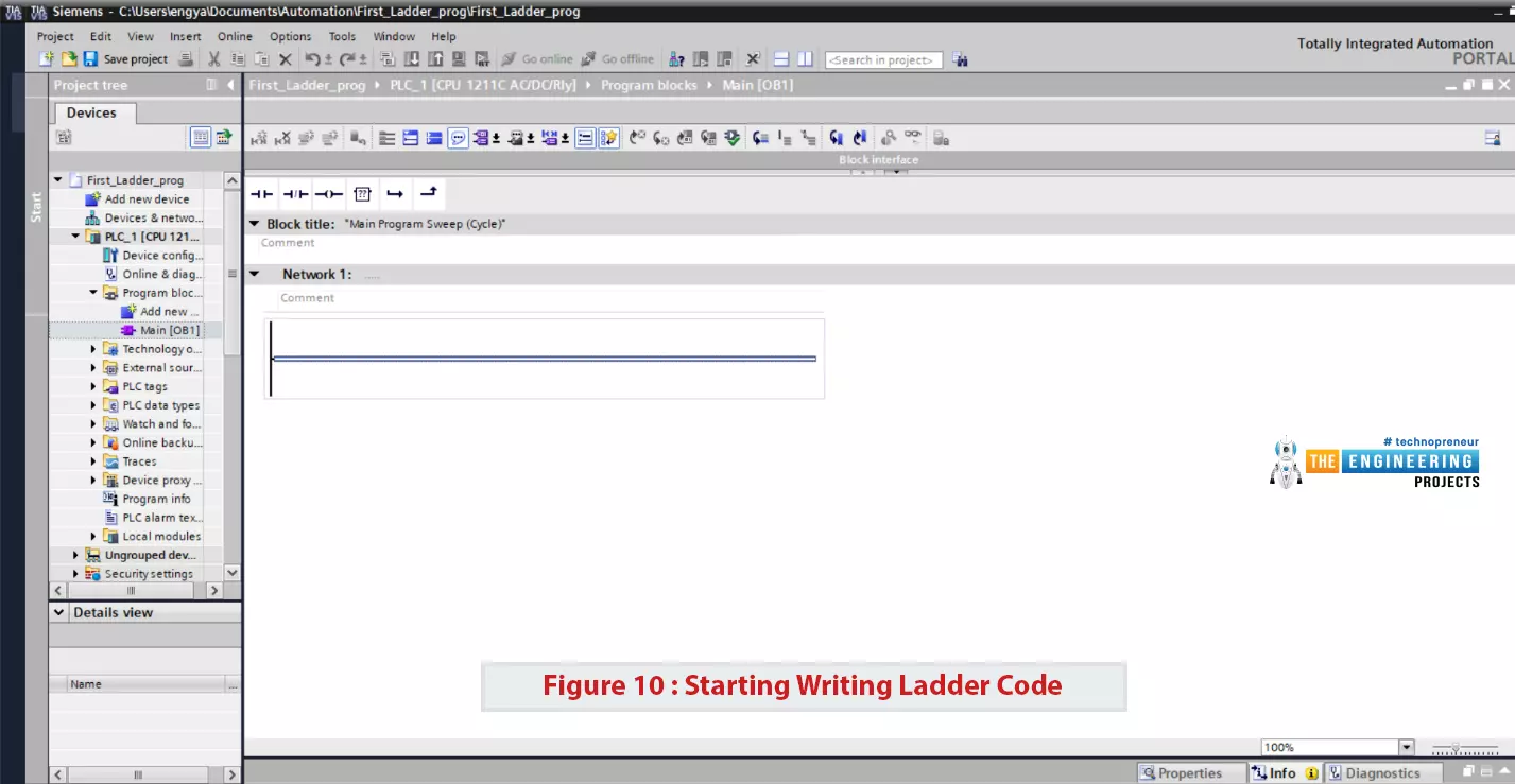
Figure 10: starting writing ladder code
Writing First program on the TIA Portal
- WOW! You are a superb learner as I can see you can follow figure 11 and by dragging a contact and dropping it on the blue line, you added a start button of normally open (NO) contact type.
- For identifying contacts and coils, the compiler assigns a unique name & address to each component and can recognize it anywhere in the program.
- Therefore, you just set the address and name for every component you add to your rung.
- The address of components has a specific format that is very logical and easy to understand.
- For example, the contact address “I0.0”, the first character is “I” which denotes input and it is followed by the number of the input module in the rack that holds all inputs and outputs modules.
- Then a number of the input channel as each input module has many channels.
- For instance, an eight channels input module can have numbers from 0 to 7 while 16 channels input module can have numbers from 0 to 15.
- A period is used to separate between the number of input modules and the channel number.
- So by set address I0.0, this refers to the very first channel in the first input module in a PLC rack.
- In addition, a name is used as a tag to easily identify the input i.e. “start” to refer to a start switch.
- Similarly, you add a stop button of the type normally closed (NC) with address I0.1 which means the second input channel in the first input module.
- Furthermore, you double-clicked the coil for the motor and set address Q0.0 which means the first output channel in the first module.
- I know you wonder what is “Q”? Yes! “Q for denoting output like “I” is denoting an input. Well done!. Now let us enjoy simulating the very first code you just have done yourself.
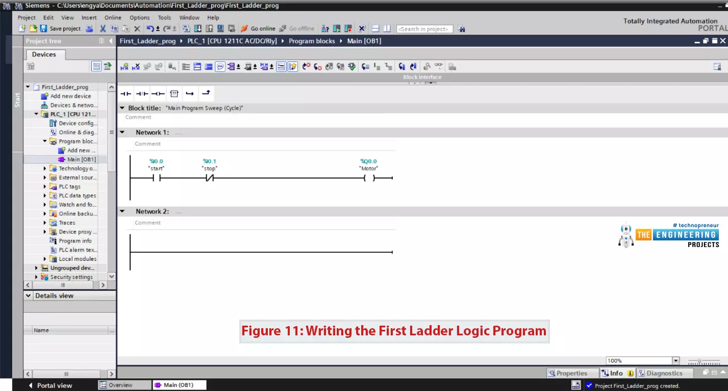
Figure 11: writing the first ladder logic program
Compiling Ladder Logic Program
- Like any programming language, the first thing to do after writing a program is to compile, to make sure it is free of error and ready to be downloaded into the PLC controller to run.
- Figure 12 shows the very simple steps to compile your program by clicking the compile icon in the toolbar which is highlighted in yellow.
- And you can notice in the lowest window below the results of compilation in blue showing that the code is free of error and warnings.
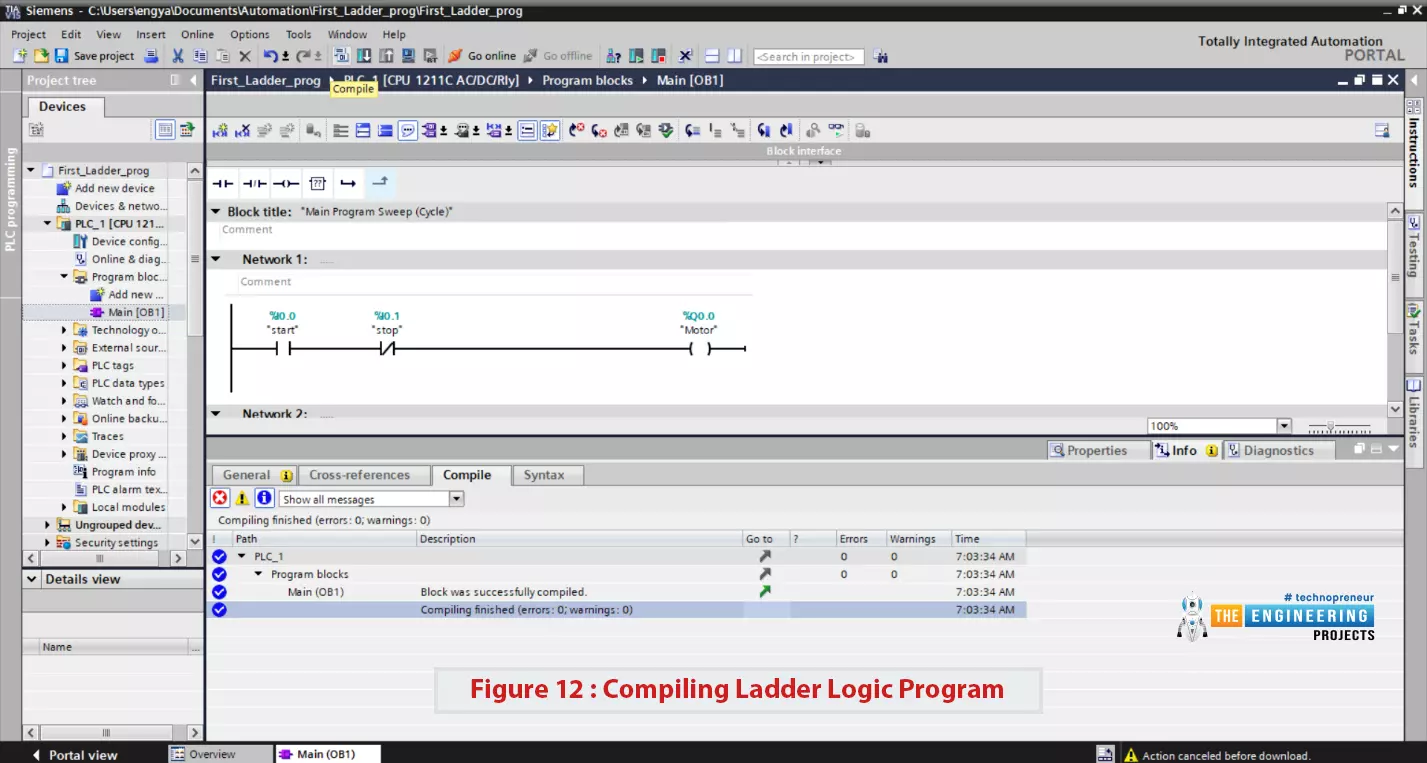
Figure 12: compiling ladder logic program
- To let you imagine how the compiler can help you to find the error location and type, we have done one mistake in the code and compiled as shown in figure 13.
- You can notice that compiler is telling the rung that has the issue which is network 1.
- In addition, the message clarifies the error by telling, you missed the required data for operand which is the address of input is missing.
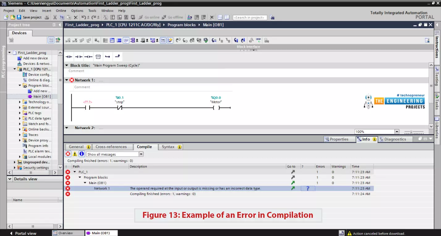
Figure 13: Example of an error in compilation
Simulating First ladder logic program
- After compiling our program successfully, now the next step is to download it to the PLC controller.
- Yes for sure our simulator will act as the plc controller.
- So, by clicking the simulator button on the toolbar, the simulator window comes out and also another window to download the program to the controller as shown in figure 14.
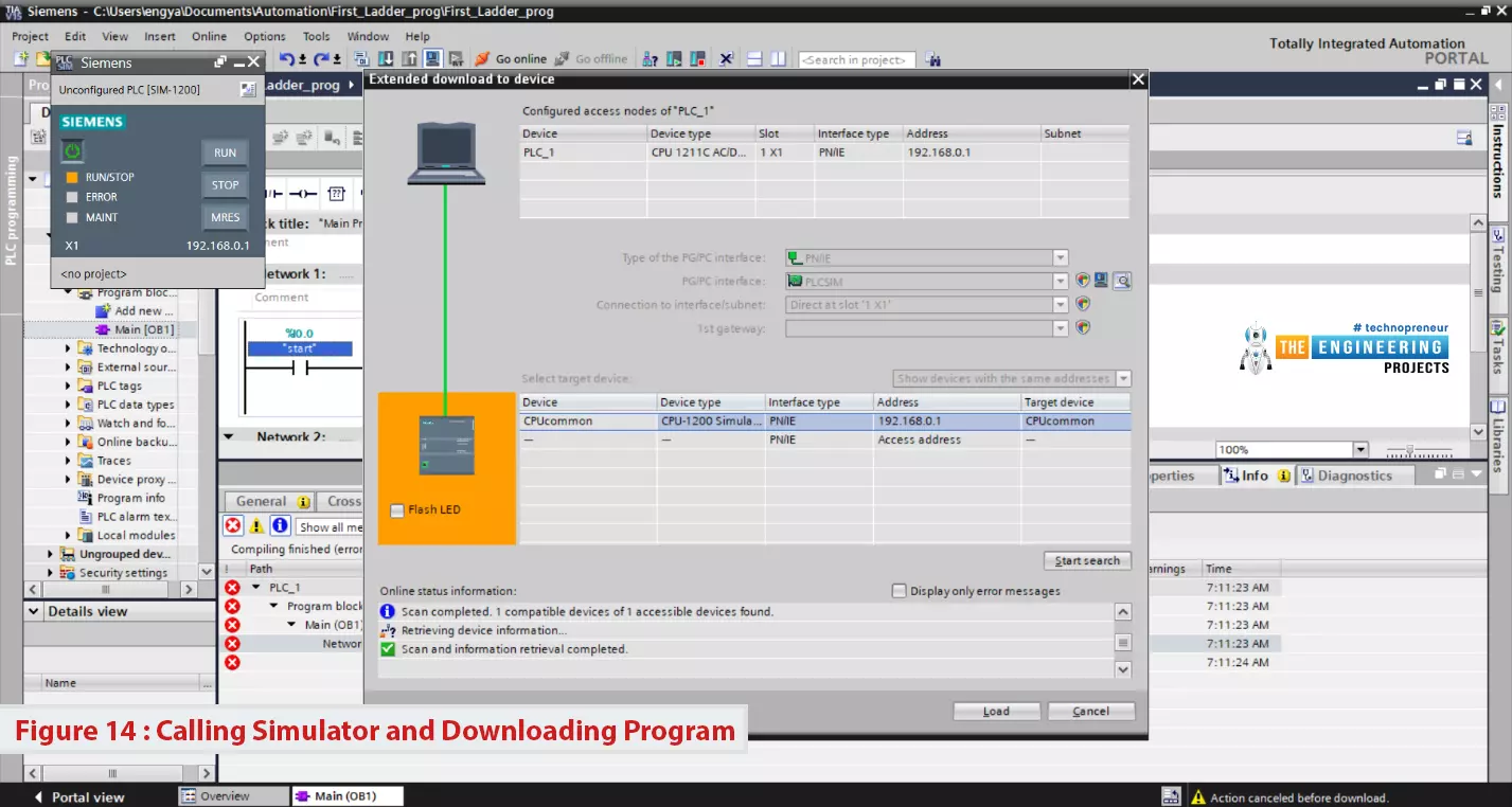
Figure 14: calling simulator and downloading program
- You simply hit the “start search” button to search for the connected PLC controller.
- In our case, the simulator will appear in the search results.
- So, you just select it and click load to proceed with the wizard of downloading your program as shown in figure 15.
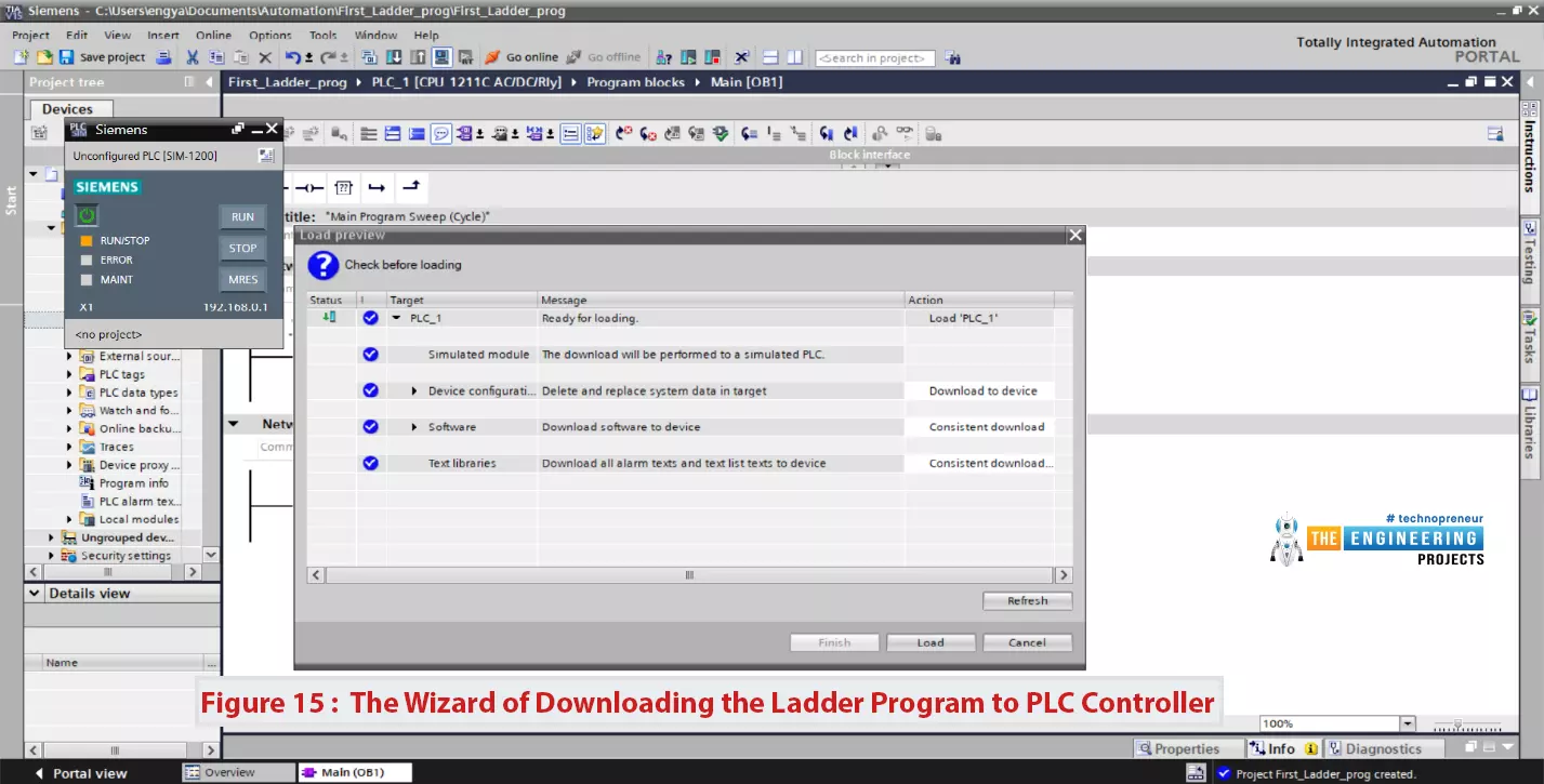
Figure 15: the wizard of downloading the ladder program to plc controller
- By reaching the last screen and clicking finished you have downloaded your first program to the simulator.
- Well done! And let's move forward with simulating our first program to validate our code and enjoy tracing the logic behavior same as a real-time plc controller.
But wait! Will you continue pressing the push button for our motor to keep running? For sure No, there should be a way to let it keep running by just hitting the button thanks to the latching technique.
Simulating our first PLC Program
- After downloading the program and pressing the run button on the very small window of the PLCSIM simulator, we can notice the run/stop indicator turned on in green showing the running status of the PLC as shown in figure 16.
- Now, click on the monitor icon on the toolbar highlighted in yellow on the most right of figure 16, you can notice the rung shows every status of each contact and coil in our program.
- I am very happy to reach this point at which you can see the normally closed contact is showing a green connection as we described above and the normally open contact showing disconnect status and can not wait until the operator press it down to connect and energize the output.
- But how do we press the buttons or switches when we are simulating? There is no physical switches or button to press!!! No friends that are not the case. Let us see how that can happen thanks to the great simulator that we have between our hands.
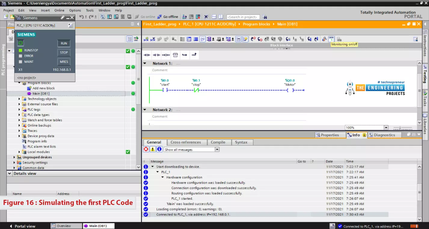
Figure 16: Simulating the first PLC code
Simulating the operator behavior
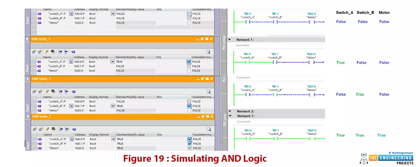
- This section is more than exciting, it shows you how the simulator not only does imitate the PLC controller but also it has the facility to imitate devices, switches, push buttons besides showing outputs’ status and values.
- In addition, we will go further in plc programming to show the series and parallel connections of contacts in branches and utilize simple logic AND, OR, NOT to form simple and complicated logics.
- The first way to set inputs on and off is by right-clicking on any contact and modifying the status to 0 or 1 as shown in figure 17.
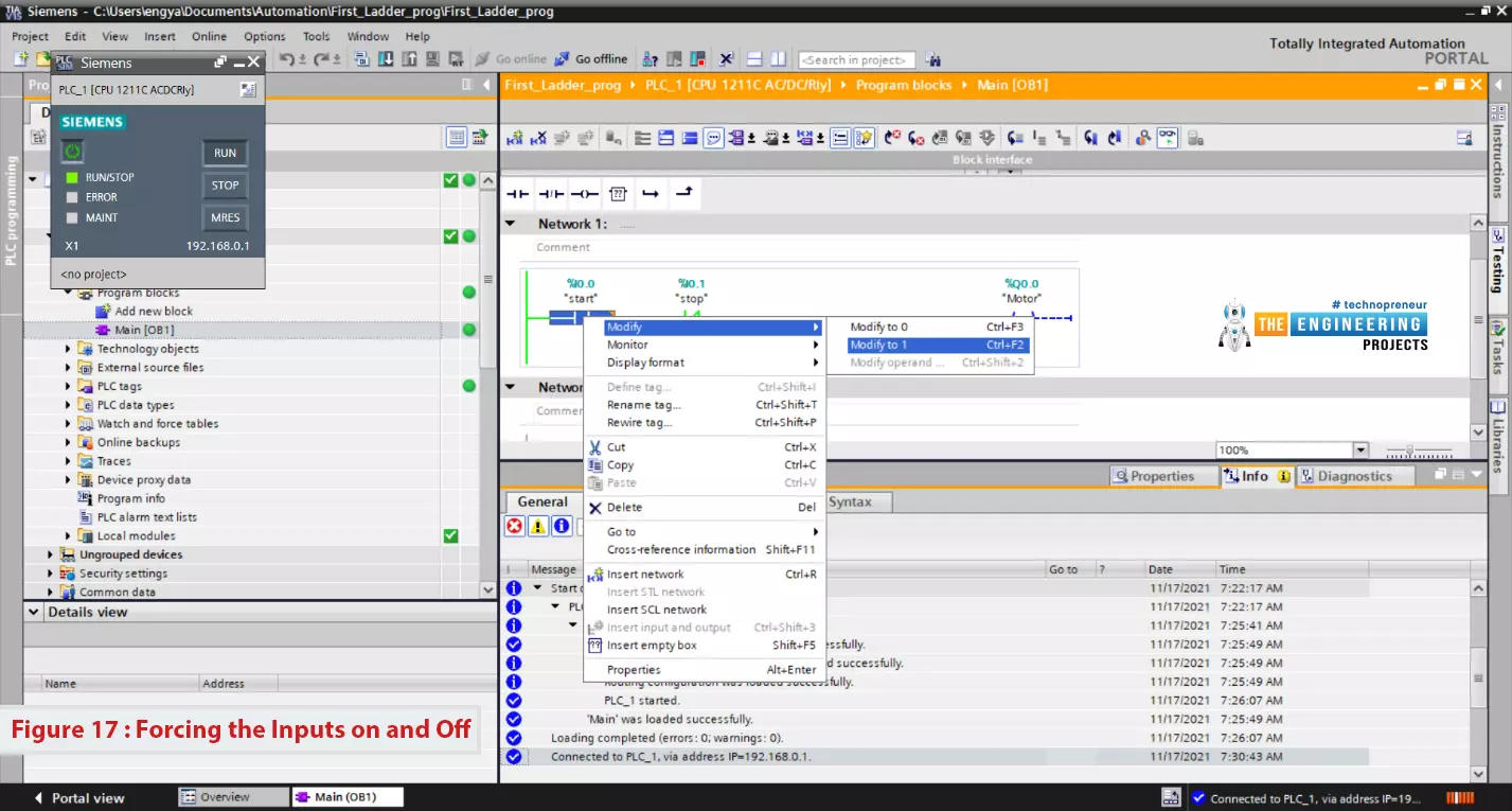
Figure 17: forcing the inputs on and off
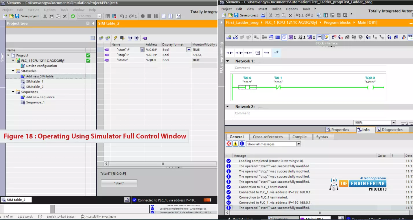
- The other way is to go to the expert mode of the full functional simulator, by hitting the which icon on the very small simulator window.
- A full version of the simulator control window will open up, where you can add inputs and outputs on the right as you can see in figure 18(left side).
- You can notice the inputs have an option in form of a check button to set it on or off.
- As a result, the contact will be turned into the selected status and the program perform according to the new status and the designed logic of your program as shown in figure 18 on the right side.
- It shows the output coil is turned to true status and highlighted in green.
- At this point, I would like to thank you my friends to follow up on our PLC tutorial series and let us move forward to learn further and do more practice with our simulating lab.
Figure 18: operating using simulator full control window
What’s next
Now, how do you see your progress so far? I can see you have just completed the most basics of ladder logic programming. You are now very familiar with the ladder basic components, using the editor to write a ladder logic program, simulate your work for verifying your logic correctness. So you are doing progressively and that’s great to hear that. However, we still have a lot to learn to master ladder logic programming. For example, using blocks like timers, counters, mathematical blocks, data comparison etc. So we hope you have enjoyed what we have reached so far in our PLC tutorial and please get yourself ready for the next part. In the next part, you will learn about types of Timers and how you set their configuration and how you utilize them to achieve the timing-based tasks accurately.