Control Project with Ladder Logic Programming


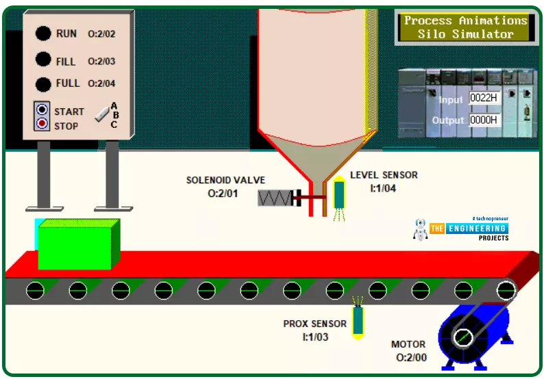
Hey guys! hope you are all very well. Today I come to you with a new process to learn, program, and simulate for practicing ladder logic more and more. The process we are going to implement today is a very common process that could be there in many many industries which is a silo process that aims to automate the process of filling containers or bottles with a liquid. Figure 1 shows the complete scene of the process including the system components, switches, indicators, sensors, and actuators that are integrated to make the system operate. Briefly and before going into deep details, let’s state what the system does and how it operates. Well! The system automatically fills the boxes that are traveling on the conveyor which is driven by a motor. They are filled with a liquid stored in the silo shown in the middle of figure 1. The process operates continuously from the moment we hit the start button shown in the tail of the control panel on the left side of figure 1 until termination of the process is requested by pressing the stop push in the same panel. Many inputs and outputs are utilized to address the sensors, switches, push buttons, motors, and valves. So let’s get started on the project.
Project Logic Philosophy
As we have thought, the first step in the development of a control system is to sit with the operator or the client to get to comprehend how the system works including all details and scenarios. So the system starts by receiving the kickoff by hitting the start pushbutton. Unless there is no stop has been requested or faults, the box moves on the conveyor that is driven by a motor until it reaches the filling station which is at the silo. At that position, the box should stop for filling, and the flow of the liquid starts and goes on until the box is full. Then, it is time for the box to continue its journey to the end of the conveyor and another box commences a new trip for filling. At any time a stop is requested, the system should halt until a command to continue is presented. Operation status should be shown thanks to indicators showing the run, fill, and full status. Now, friends, that’s all the story we have gotten by sitting with the client or the operator who requested us to implement his system. have understood the requested silo operation? Well done! I know it is simple to understand but what is the next step? Yes, the next station in the project is to interpret the story narrated by our client into operation sequences and conditions and determine the list of inputs and outputs to get that project done.
Logic sequence
The aims of the project we are going to implement is to implement the ladder logic program that execute the narrated logic of SILO by client. The logic can be resumed in the following sequence of operations:
The batch process can be started or stopped at any point of execution
Indicator lamps should be appropriately controlled to present the run, fill, and full statuses of the operation throughout the whole process.
All actuators should be stopped at any time a termination requested by the end user
The FULL lamp is switched on showing the full status of the box as long as the box at its filling position under the silo.
After converting the logic narrative received from the client into clear logic sequences, now the time comes to list the inputs and outputs to use to accomplish these logic sequences. In the next section, the complete list of inputs represented by sensors and switches and outputs represented by motors, valves, and light indicators.
Project I/Os
Figure 2 shows the location and address of all inputs and outputs used in this project. Also, the table below lists all inputs and outputs of the project including descriptions and addresses. The control panel on the lift shows two inputs that enable an operator to start and stop the operation. Also, it shows indicators showing the status of the operation throughout the whole process. These status indicators are RUN. FILL, FULL to show the process is running, the box is filling, and when it is full. Also, it shows the motor that drives the conveyor and the proxy sensor that detects the position where the box is exactly under the silo and ready to be filled for initiating the filling process. Also, a level sensor is utilized to determine when the box is filled up to full. In addition, a valve is used to open and close the silo.
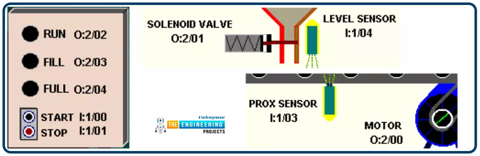
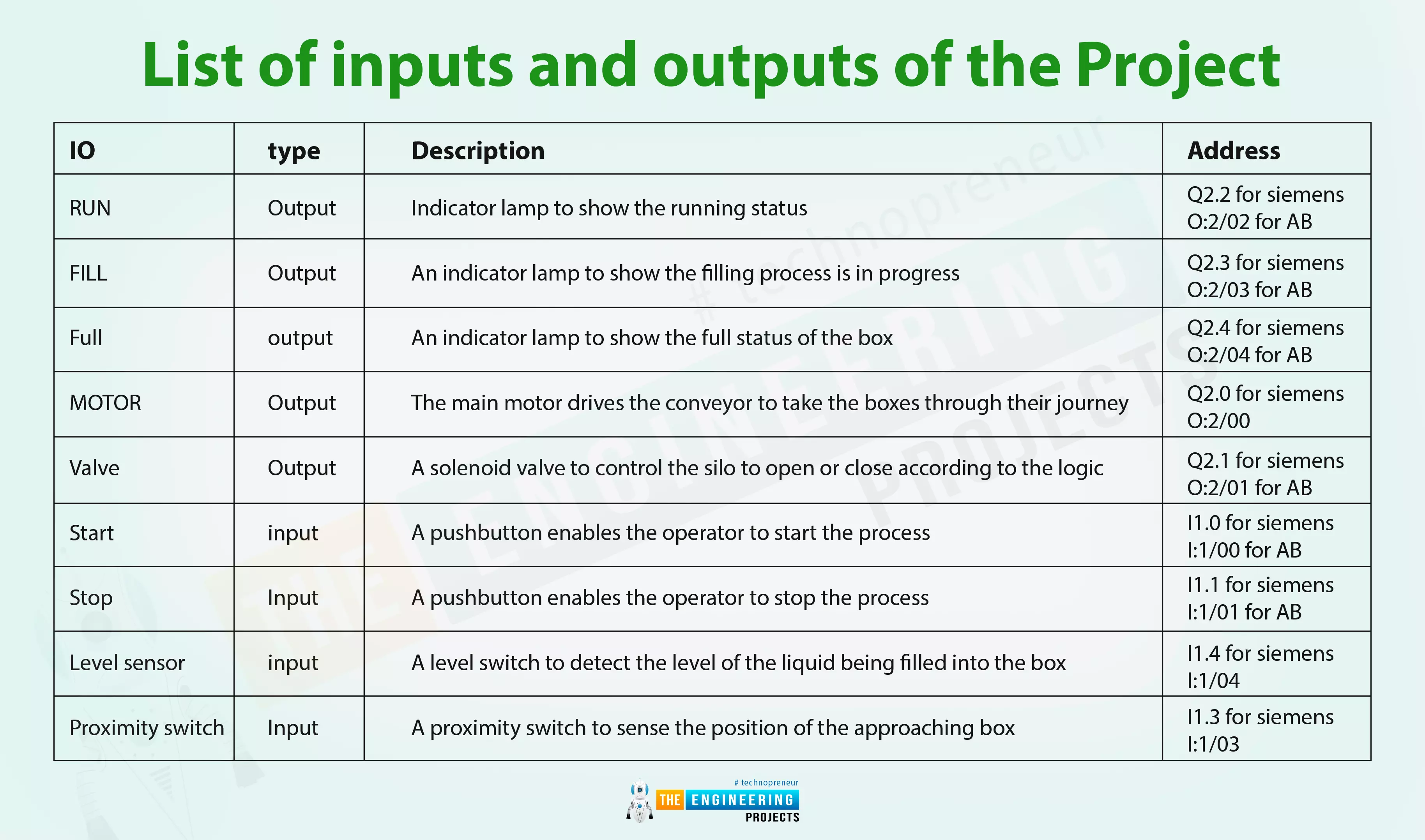
Table 1: list of inputs and outputs of the project
IO |
type |
Description |
Address |
RUN |
Output |
Indicator lamp to show the running status |
Q2.2 for siemens O:2/02 for AB |
FILL |
Output |
An indicator lamp to show the filling process is in progress |
Q2.3 for siemens O:2/03 for AB |
Full |
output |
An indicator lamp to show the full status of the box |
Q2.4 for siemens O:2/04 for AB |
MOTOR |
Output |
The main motor drives the conveyor to take the boxes through their journey |
Q2.0 for siemens O:2/00 |
Valve |
Output |
A solenoid valve to control the silo to open or close according to the logic |
Q2.1 for siemens O:2/01 for AB |
Start |
input |
A pushbutton enables the operator to start the process |
I1.0 for siemens I:1/00 for AB |
Stop |
Input |
A pushbutton enables the operator to stop the process |
I1.1 for siemens I:1/01 for AB |
Level sensor |
input |
A level switch to detect the level of the liquid being filled into the box |
I1.4 for siemens I:1/04 |
Proximity switch |
Input |
A proximity switch to sense the position of the approaching box |
I1.3 for siemens I:1/03 |
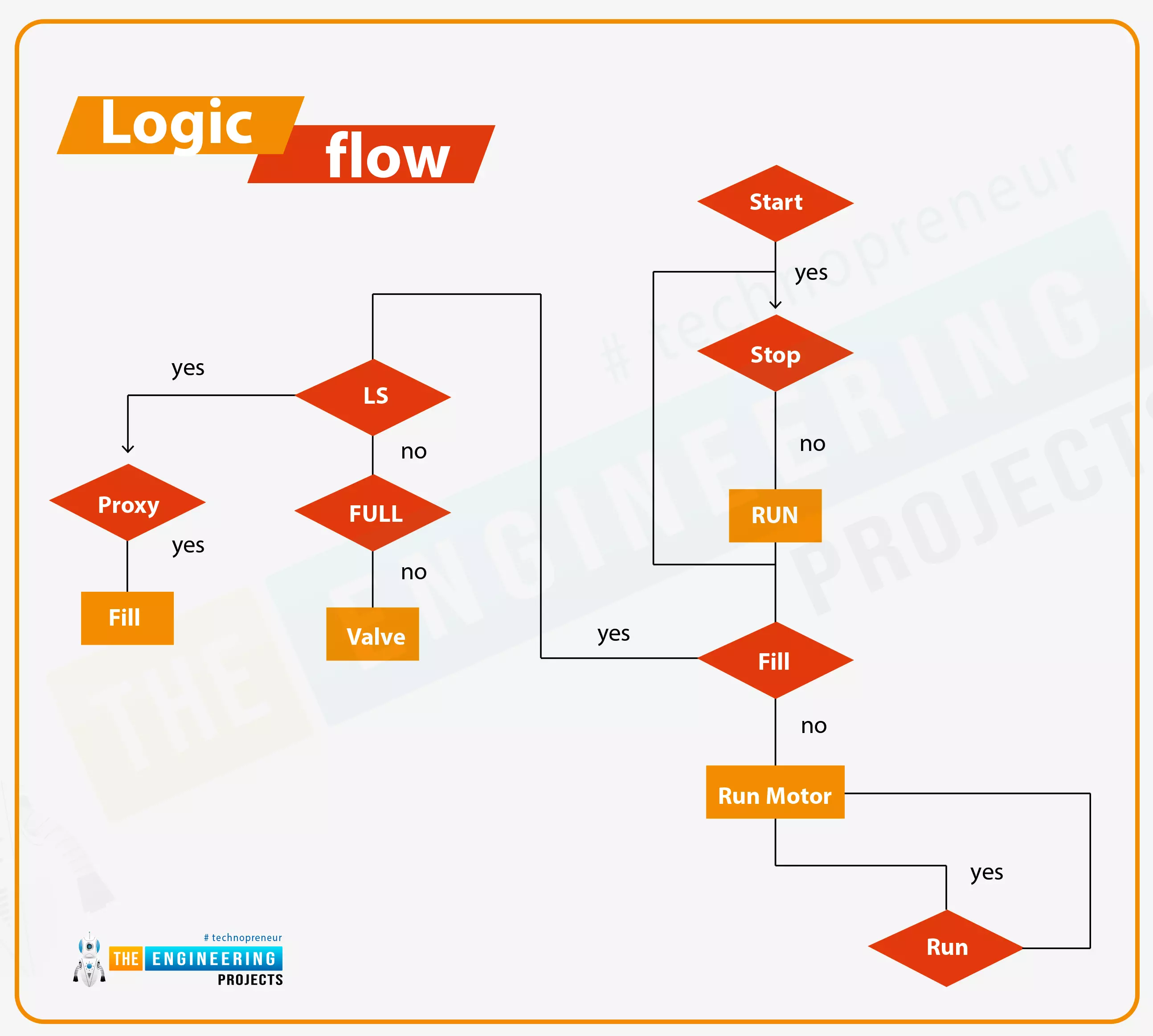
Logic Flow Diagram
Guys, this is not an essential step to accomplish the project development. But this is one of the professional ways to represent graphically the design of the logic. Figure 3 depicts the logic of the silo project graphically. You can follow paths of logic to understand how we can chart the logic flow running in our head graphically to help in writing the correct and precise code. For example, to run the conveyor motor, the start button is pressed and checked if a stop is requested, if not the run lamp indicator will be energized and latched as long as no stop is requested. Then check if a fill process is in progress. If not then the motor of the conveyor will keep running. But the question is how to know if the fill is in progress or not. On the left side of the chart, you can see if the proxy switch is on and the level switch does not show full, then the filling process is in progress. Also, if the level switch shows not full then the valve will keep open to continue filling the boxes.
Ladder Logic Programming of the project
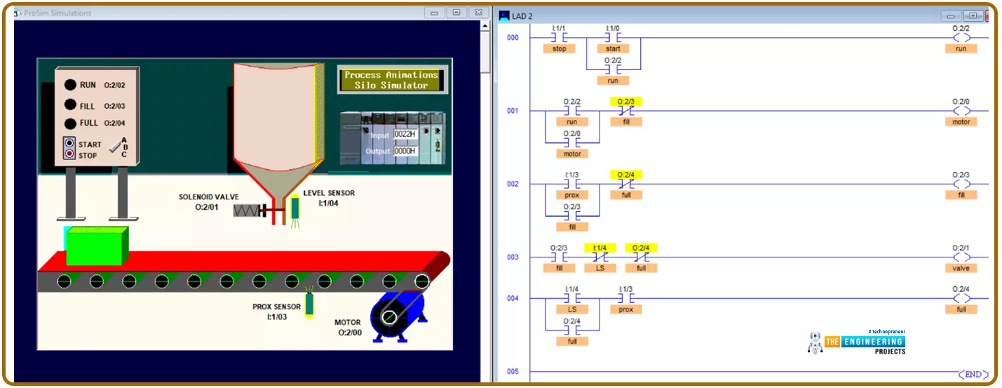
Now we have just arrived at what you are waiting for! I know you want to practice programming and then simulation. Figure 4 shows the program of the silo project while the left part shows the initial state of our simulation. The first rung is to energize the run indicator when the start pushbutton is hit and no stop is requested noting the latch as we have learned. In the second rung, knowing the run is the status of the operation and no filling process is in progress, then the motor is running. In the third rung, the filling status can be determined by the proximity switch showing the boss is at the position were ready to fill and full status is not there. While the full status can be determined in the last rung when the level switch is on showing level has reached the full limit of the box and pursuing the proximity switch tells the box is on the filling spot. Before that very last rung, the valve of the silo can be determined by having the fill status on and the full status is not there yet.
Simulating the program
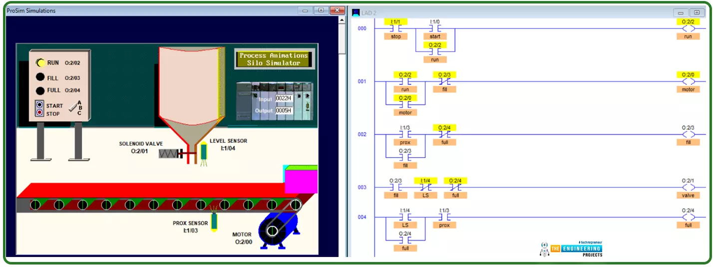
After showing you the code of the design step by step based on the received narrative from the client, deciding the IOs, and charting the logic of the program. Now it is time to simulate the program to make sure the design and the code are correct. Figure 5 shows the running status of the operation. By hitting the start push button, the conveyor move by the driving motor and takes the box to the filling station. Guys, notice please the run indication lamp is on in the code highlighted in yellow and on the control panel on the right as well. Also, notice the motor is spinning.
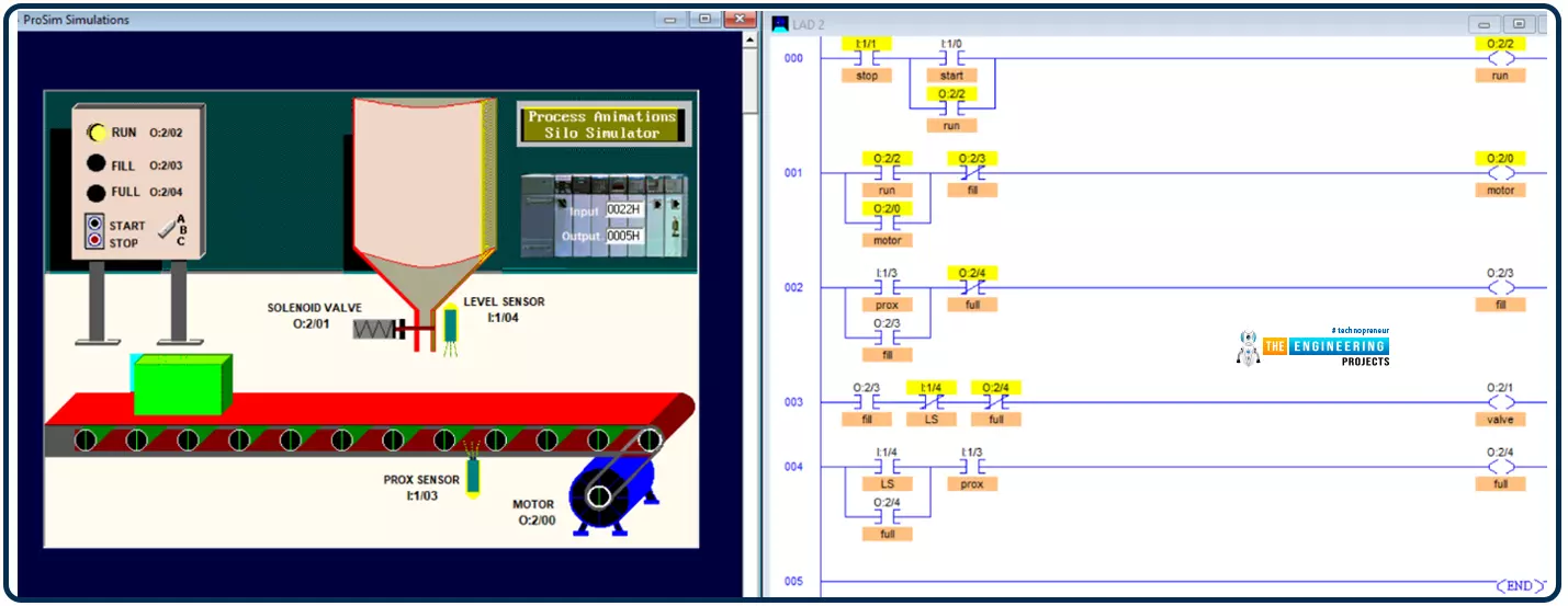
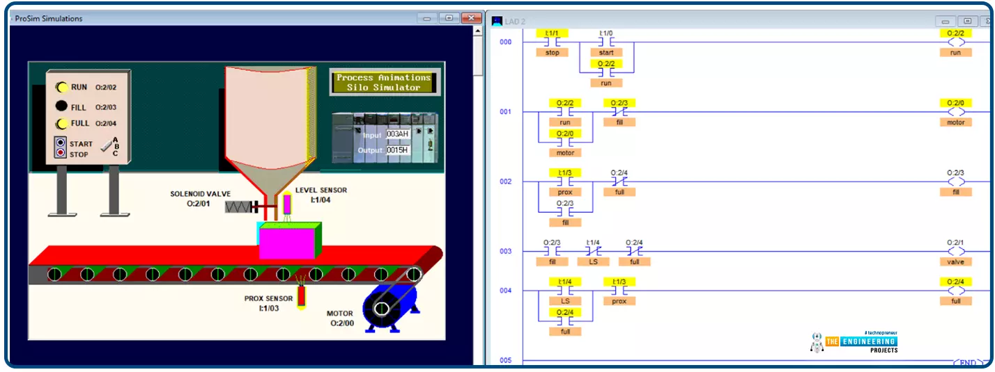
Figure 6 shows the box stopped for filling at the silo thanks to the proximity switch. Notice the run lamp is on and the motor is de-energized for letting the box fill. Also, notice the fill status is on and the lamp indicator is energized. Also, see the valve is open to let the liquid fills the box.
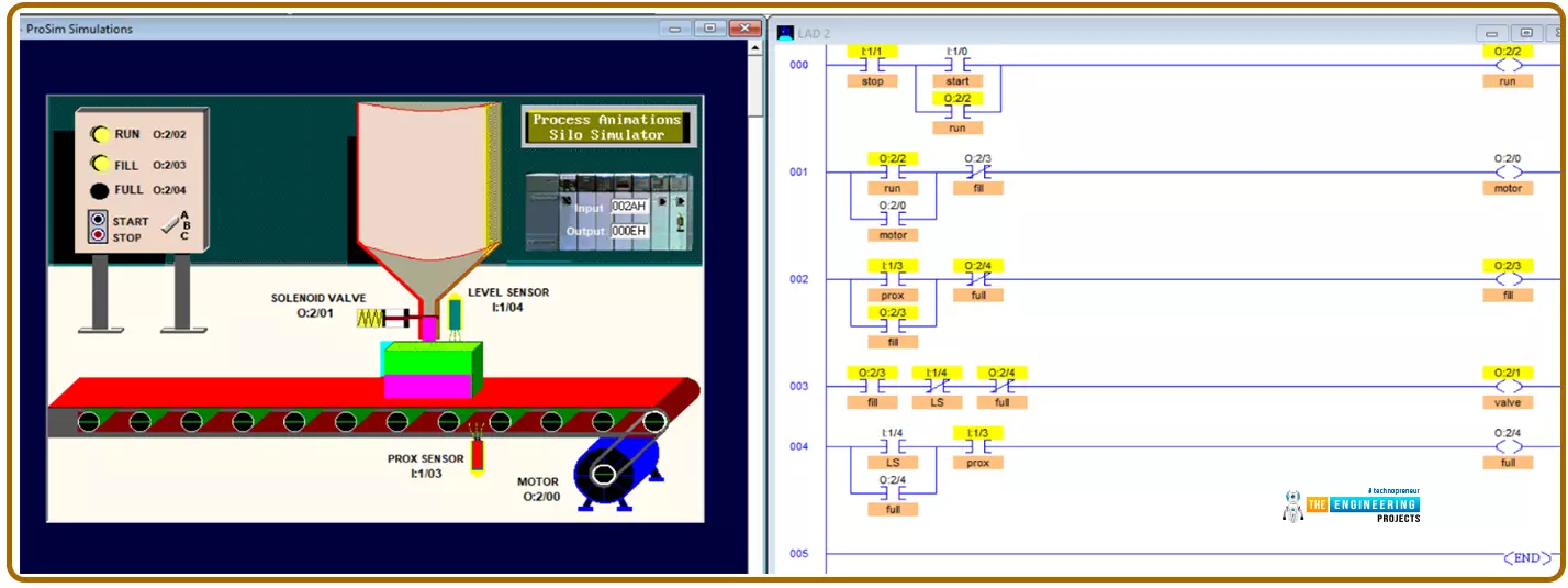
Figure 7 shows when the box comes to be full. You can see the run operation status is still on. And the full status is indicated by the full lamp. Also, once the box is full, the motor starts spinning again taking the filled box out from the line to let other incoming boxes come.
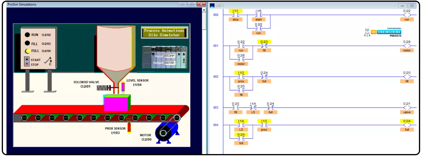
And finally, after filling to full, the filled boxes keep going as shown in figure 8 to the end of the conveyor. You can see the run status is still energized and the motor is spinning. After that, the cycle will continuously be repeated until the stop is requested. So let us see the termination of the process.
on the other hand, when the stop push button is pressed requesting termination of the process, the motor stops spinning and the whole process stopped until a proceeding instruction is issued by hitting start again. Guys, that is very common to enable the machine operator to stop for any emergence or do any repainting before baking to work again
What is next???
First of all, I would like to thank you all for continue following the tutorial till this very point. As you see we are taking projects from real life. It might be small projects or processes but that is what you will see in real industry life. So next time we select one of the common processes in the real life and do the same design, coding, and without question practicing using our simulator. So please be ready, study hard, and let’s meet for our next project.