Hello friends, I hope you are doing well. In today's tutorial, I am going to share our BMP280 Proteus Library. With this library, we can connect a BMP280 pressure sensor to an Arduino Uno, change the simulated temperature and pressure, and display the readings on a Virtual Terminal. The component includes two interactive sliders, so we can test different conditions without changing the Arduino program.
We will follow the same flow as our other Proteus library tutorials: understand the sensor, download and install its files, check the wiring, and run the supplied example. After that, we will explain the Arduino code, pressure units, compensation and a useful altitude calculation. The download includes the connected project, compiled HEX and editable source, making the first experiment straightforward.
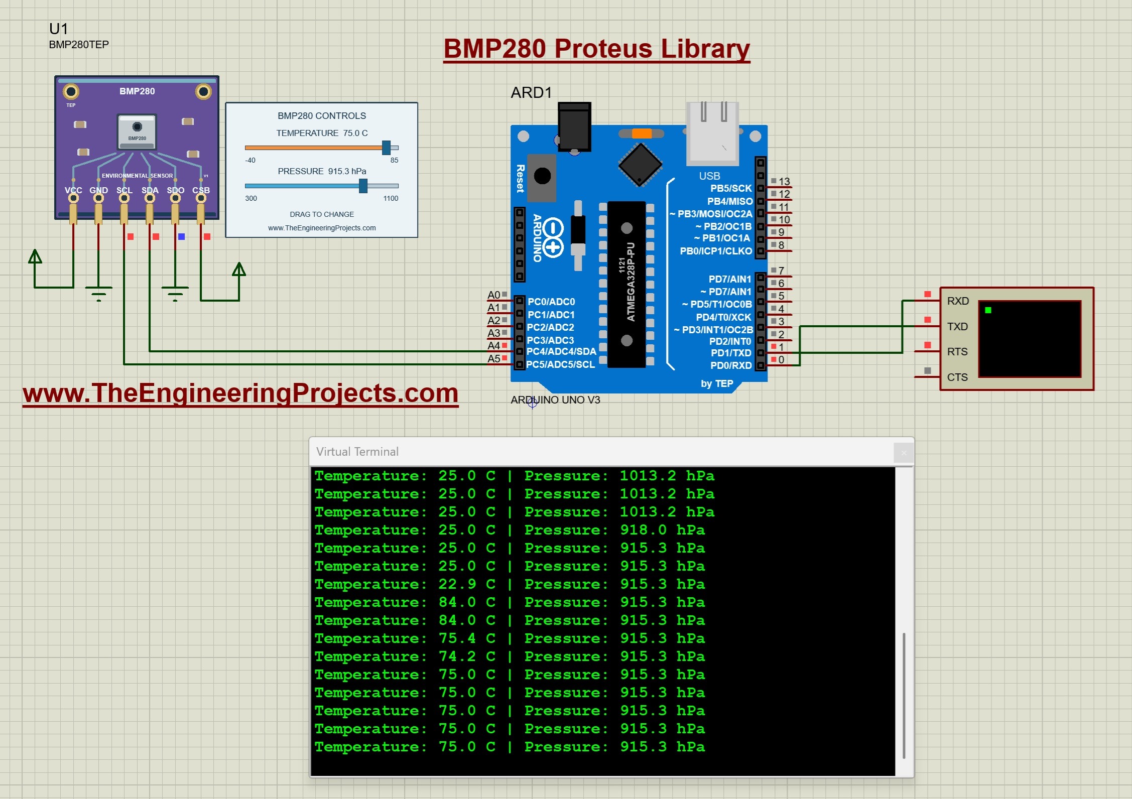
The package targets Proteus 8.5 with AVR simulation support and uses our TEP Arduino UNO V3.0 at 16 MHz. In the running screenshot below, the final readings are approximately 75.0 C and 915.3 hPa. We will start with the documented default conditions, then learn how to reproduce changes like these.
What Is the BMP280 Sensor?
The BMP280 is a digital barometric pressure and temperature sensor. Its pressure measurement is an absolute pressure referenced to vacuum, rather than a difference between two external pressure ports. Temperature is also used during pressure compensation, so the two measurement paths are connected inside the calculation.
Our Arduino communicates with the sensor over I2C. The sensor exposes raw measurements and calibration values, and the programming library converts those values into temperature and pressure. We therefore need to understand both the physical quantity and the units returned by the library.
Pressure is commonly expressed in pascals, written as Pa, or hectopascals, written as hPa. The prefix hecto means one hundred, so 1 hPa = 100 Pa. The supplied program displays hPa because that unit produces convenient numbers for atmospheric-pressure examples.
The Proteus component is named BMP280TEP. Its sliders supply simulated conditions to the register model. They do not read the temperature of your computer, the weather at your location or a physical sensor attached to your USB port.
BMP280 and BME280 Are Different Sensors
The similar names can be confusing. The BMP280 provides pressure and temperature, while the BME280 also provides humidity. A BMP280 sketch and component should not be expected to return humidity merely because a BME280 tutorial uses a similar-looking board.
| Feature | BMP280 | BME280 |
|---|---|---|
| Temperature | Available | Available |
| Pressure | Available | Available |
| Humidity | Not available | Available |
| Programming library in our examples | Adafruit BMP280 | Adafruit BME280 |
If your project needs humidity, use our BME280 Sensor Library for Proteus. For this tutorial, keep the BMP280 device, driver and supplied firmware together.
Download the BMP280 Library for Proteus
First of all, download the package using the button below. Extract the complete archive into a normal folder and keep its directory structure together.
Download BMP280 Proteus Library V1.0 and Arduino SimulationThe archive is named BMP280-TEP-v1.0-test.zip and retains its original test-package notes. This tutorial follows the supplied circuit and screenshots. Proteus 8.5 is the target version; the screenshots do not establish compatibility with Proteus 7 or every other release.
| Folder | Contents and purpose |
|---|---|
| Proteus Library Files | TEPBMP280.LIB and the TEP Arduino UNO V3.0 LIB/IDX files. |
| Proteus Model Files | TEPBMP280.DLL, the functional sensor model. |
| Proteus Simulation | BMP280-ArduinoUnoV3.pdsprj, BMP280_Demo.hex and a local sensor DLL. |
| Arduino Code | The example sketch, driver sources, AVR core archive and rebuild script. |
| Model Source and Documentation | The model implementation, behavior notes and third-party notices. |
The LIB gives Proteus the device definition, the DLL supplies its functional behavior, and the Arduino library provides the functions used by the sketch. These files have separate jobs. Copying the Arduino source into a Proteus library folder will not install the simulation component.
How to Install the BMP280 Proteus Library
Save your work and close Proteus before copying the files. We will install the sensor and its model, then restart Proteus to load the component.
- Open the extracted Proteus Library Files folder.
- Copy
TEPBMP280.LIBinto the library directory configured for your installation. - Add
ArduinoV3TEP.LIBandArduinoV3TEP.IDXif our TEP Arduino UNO V3.0 library is not already installed. - Copy
TEPBMP280.DLLfrom Proteus Model Files into the configured Proteus MODELS directory. - Restart Proteus, open Pick Devices and search for BMP280TEP.
- Place the component, or open the supplied project to begin with its completed circuit.
Use your installation's actual library and model search paths; their locations can differ between versions. The sensor is supplied as a native LIB without a separate TEPBMP280.IDX in this archive. Do not rename another device's index file to create one.
Keep the additional DLL beside the example project. The sensor uses the DLL model, while BMP280_Demo.hex belongs to the Arduino's Program File property. The included board is the one described in our Arduino Library for Proteus V3.0 tutorial.
BMP280 Pinout and Arduino Uno Wiring
The six pins along the lower edge are VCC, GND, SCL, SDA, SDO and CSB. Start each wire at the exposed endpoint below its pin. For this example, SDO and CSB are configuration connections that must be set deliberately.
| Sensor pin | Connect to | Purpose |
|---|---|---|
| VCC | Positive supply rail | Enables the powered model. |
| GND | Common ground | Shared reference. |
| SCL | Arduino Uno A5 | I2C clock. |
| SDA | Arduino Uno A4 | I2C data. |
| SDO | Ground | Selects address 0x76. |
| CSB | Positive supply rail | Must be high for this model's I2C operation. |
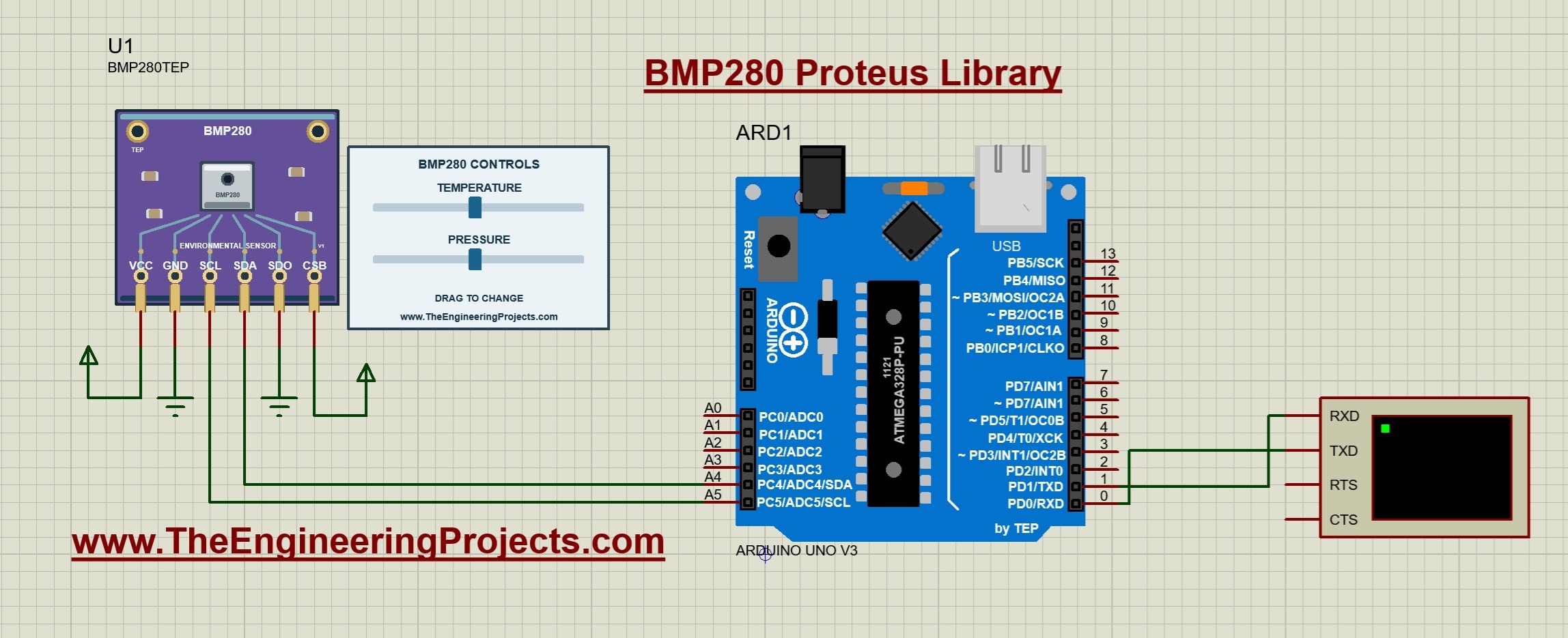
Connect Arduino D1/TX to Virtual Terminal RXD. Set the terminal to 9600 baud, eight data bits, no parity and one stop bit, and confirm that the Uno clock is 16 MHz. The return serial wire to D0/RX is shown in the circuit, but the sketch does not require incoming commands.
SDO selects the seven-bit I2C address: low gives 0x76 and high gives 0x77. The supplied sketch calls sensor.begin with 0x76, so its circuit grounds SDO. Changing the address connection without changing the program causes initialization to fail.
The demonstration uses the AVR Wire implementation's internal pull-ups in the digital simulation. For physical hardware, check the breakout's supply and logic-voltage requirements and use suitable I2C pull-ups. This model does not reproduce the module's regulator, power consumption or analog bus behavior.
Run the BMP280 Simulation in Proteus
- Open
Proteus Simulation/BMP280-ArduinoUnoV3.pdsprjfrom the extracted package. - Keep BMP280_Demo.hex and TEPBMP280.DLL beside the project.
- Check the Arduino's Program File, 16 MHz clock and 9600 baud terminal.
- Confirm SDO is grounded and CSB is connected high.
- Press Run, open the terminal window and let several readings appear.
The documented defaults are 25 C and 1013.25 hPa. The terminal prints one decimal place, so the initial pressure appears around 1013.2 hPa in the screenshot. The panel and terminal can differ slightly because raw conversion, compensation and display rounding occur at different stages.
Now change pressure while leaving temperature fixed. The pressure readings should follow the selected input. Then hold pressure steady and move the temperature slider. In the featured screenshot, pressure settles at 915.3 hPa and the final temperature settles at 75.0 C.
Read the newest terminal lines when comparing a slider value with the output. Older lines retain the previous conditions, including intermediate values selected while dragging. Allow several print intervals after a change before deciding that a reading is stuck.
Using the Temperature and Pressure Controls
| Property | Range | Default |
|---|---|---|
| TEMPERATURE | -40 to +85 C | 25 C |
| PRESSURE | 300 to 1100 hPa | 1013.25 hPa |
During simulation, drag a blue handle or click its track. The model changes the selected environmental input and returns measurements through I2C. It does not directly write text into the Virtual Terminal.
For an exact starting condition, stop the simulation and edit the component properties. Restarting restores those saved values. A slider movement affects the current run without permanently replacing the initial property.
The two inputs are independently adjustable. The model does not calculate atmospheric weather or automatically lower pressure when you increase temperature. This independence is useful for checking whether your code handles each quantity correctly.
Arduino Code for the BMP280 Sensor
The following code is the exact sketch included in the ZIP. It uses version 3.0.0 of the Adafruit BMP280 library. The package includes the driver and its dependencies so you can reproduce the supplied firmware.
#include <Wire.h>
#include <Adafruit_BMP280.h>
Adafruit_BMP280 sensor;
bool ready=false;
void setup() {
  Serial.begin(9600); Wire.begin(); Wire.setWireTimeout(25000,true);
  ready=sensor.begin(0x76);
  if(!ready) { Serial.println(F("BMP280 not found. Check SDA, SCL, SDO/GND and CSB/VCC.")); return; }
  sensor.setSampling(Adafruit_BMP280::MODE_NORMAL,Adafruit_BMP280::SAMPLING_X1,
    Adafruit_BMP280::SAMPLING_X1,Adafruit_BMP280::FILTER_OFF,Adafruit_BMP280::STANDBY_MS_125);
  Serial.println(F("TEP BMP280 - drag the temperature and pressure sliders.")); delay(100);
}
void loop() {
  if(ready) {
    Serial.print(F("Temperature: ")); Serial.print(sensor.readTemperature(),1);
    Serial.print(F(" C | Pressure: ")); Serial.print(sensor.readPressure()/100.0,1); Serial.println(F(" hPa"));
  }
  delay(500);
}
Initialize the Sensor
The setup function opens the serial port at 9600 baud and initializes Wire. It sets a timeout of 25,000 microseconds, or 25 ms, with reset enabled after a timeout. The call sensor.begin(0x76) initializes the BMP280 at the selected address.
The ready variable records whether initialization succeeded. If it fails, the program prints the connections to check and does not display normal measurements. After correcting a wire or address, restart the simulation so setup runs again.
Choose Sampling and Filtering
The setSampling call selects normal mode, temperature oversampling x1, pressure oversampling x1, filter off and a 125 ms standby period. Normal mode repeats conversions automatically. The main loop can then read the latest available result.
Oversampling and standby affect the sensor's conversion schedule. They are separate from the sketch's 500 ms delay between printed lines. Increasing how often the program reads a register does not automatically increase how often the sensor completes a new conversion.
The model also supports forced and sleep modes. A forced measurement performs one conversion and returns to sleep, while normal mode repeats. When experimenting with a different mode, use the driver's corresponding measurement calls instead of assuming the existing polling loop will trigger every conversion.
Read Temperature and Pressure
The program calls readTemperature to obtain Celsius and readPressure to obtain pascals. It divides the pressure by 100.0 before printing hPa. For example, 91530 Pa / 100 = 915.3 hPa. Omitting this division would make the displayed number one hundred times larger than the selected hPa value.
Both readings are formatted to one decimal place. That formatting makes the output easy to compare with the panel, but it does not mean the real sensor has an accuracy of 0.1 C or 0.1 hPa. Display precision and measurement accuracy are different quantities.
How Pressure Compensation Works
The sensor interface contains calibration coefficients as well as raw measurement registers. The library reads those coefficients and applies temperature and pressure compensation. There is no single universal divider that turns a raw BMP280 pressure count directly into hPa.
Each raw measurement occupies 20 bits spread across three bytes. If those bytes are MSB, LSB and XLSB, the value is raw = MSB × 4096 + LSB × 16 + floor(XLSB / 16). The bottom four bits of XLSB are not part of that 20-bit count.
Temperature compensation produces an intermediate value commonly called t_fine. Pressure compensation uses that intermediate value along with its own coefficients. This is why working temperature conversion matters even if your application is mainly interested in pressure.
Our functional model provides synthetic calibration and suitable raw ADC values. The Arduino driver performs compensation through its normal code path. The sliders therefore test the communication and conversion sequence rather than bypassing it with preformatted text.
Because the model must select integer ADC counts, the compensated result may be slightly above or below the requested input. Judge small differences in the context of quantization and one-decimal output. A large constant factor usually points to a unit error, while failed initialization points first to wiring, address or driver selection.
Measurement Timing and Filter Response
For x1 temperature and x1 pressure oversampling, this model uses 1.25 + 2.3 + 2.3 + 0.575 = 6.425 ms of conversion time. Adding the configured 125 ms standby gives about 131.425 ms per normal-mode cycle, or approximately 7.6 cycles per second.
The supplied sketch prints more slowly, approximately twice per second with additional execution and serial-output time. It can therefore skip over intermediate completed conversions while still printing the latest value. This is expected for a simple display example.
The default filter is off. When an IIR coefficient is selected, the model updates a filtered raw value using new filtered value = previous value + (new sample - previous value) / coefficient. A larger coefficient reduces the change per conversion and produces a slower step response.
This behavior is useful for comparing response speed with smoothing. It is a functional implementation, not a reproduction of random sensor noise or physical tolerances. Keep the original settings for your first test, then change one sampling parameter at a time.
Estimate Altitude from Pressure
Pressure decreases with increasing altitude under typical atmospheric conditions, so a barometer can support an altitude estimate when a reference pressure is known. The BMP280 does not directly measure height; the calculation makes assumptions about the atmosphere.
A commonly used standard-atmosphere approximation is altitude in meters = 44330 × [1 - (P / P0)^0.1903], where P is the measured pressure and P0 is the chosen sea-level reference. Use the same pressure units for both values so their ratio is dimensionless.
Using the screenshot's 915.3 hPa and a reference of 1013.25 hPa gives approximately 849.4 meters. This is a worked calculation for those inputs, not a claim that the simulated board is physically at that elevation. The supplied sketch does not print altitude unless you extend it.
Weather changes the appropriate reference pressure. Using a fixed 1013.25 hPa reference everywhere can produce an apparent altitude change while a real sensor remains stationary. Decide whether your application needs a standard-reference estimate or a locally calibrated height estimate before interpreting the number.
Compile and Test Your Own Changes
- Open
Arduino Code/BMP280_Demo/BMP280_Demo.inoin Arduino IDE. - Select Arduino Uno and the documented Arduino AVR Boards 1.8.6 core.
- Install the included Adafruit BMP280, Adafruit BusIO and Adafruit Unified Sensor libraries.
- Compile and export the application HEX after editing the sketch.
- Select the new HEX in the Uno's Program File property, retain the clock and terminal settings, and restart.
The supplied HEX is enough for the initial experiment. The package also includes an AVR core archive and portable rebuild script, with the required compiler paths described in its README. Editing the INO file alone does not change the firmware loaded by Proteus.
For a repeatable test, start at the defaults, reduce pressure while holding temperature fixed, increase temperature while holding pressure fixed, and then stop and restart. Confirm that the configured starting values return. Afterward, try a different filter setting and compare how many readings it takes for a step to settle.
Common Problems and Their Solutions
| Problem | What to check |
|---|---|
| BMP280TEP is missing from Pick Devices. | Check TEPBMP280.LIB in the active library path and restart Proteus. |
| The sensor drawing appears but the model cannot load. | Check TEPBMP280.DLL in MODELS and beside the project. |
| The sketch reports BMP280 not found. | Check SDA/A4, SCL/A5, common ground, SDO low and CSB high. Confirm the BMP280 driver is being used. |
| Terminal output is blank or unreadable. | Check the HEX path, D1/TX to terminal RXD, 16 MHz clock and 9600 baud. |
| Pressure is one hundred times the expected value. | Convert the driver's pascal result to hPa by dividing by 100. |
| The reading approaches a changed input slowly. | Check whether an IIR filter was enabled and allow enough conversions to settle. |
| Humidity is missing. | BMP280 does not provide humidity. Use the BME280 example when humidity is required. |
| Source changes do not affect the simulation. | Compile a new HEX and update the Arduino's Program File. |
Practical Review and FAQs
This library is useful for learning I2C initialization, calibration-based conversion, pressure units and sampling behavior. Independent temperature and pressure inputs let us reproduce a condition and check the firmware response. The model covers I2C operation, compensation, sleep, forced and normal modes, oversampling timing, standby and IIR response.
SPI, physical sensor noise and component tolerances are outside this version's scope. Although the board has familiar SDO and CSB labels, this tutorial uses the modeled I2C interface. Use physical measurements to evaluate real-board accuracy, power and environmental behavior.
Can I Use Address 0x77?
Yes. Set SDO high and change the address passed to sensor.begin to 0x77. Keep CSB high. Change the wiring and firmware together.
Do I Need a HEX File for the Sensor?
The sensor uses TEPBMP280.DLL. Load BMP280_Demo.hex into the Arduino, not into the sensor.
Why Does Pressure Read About 1013.2 Instead of 1013.25?
The output uses one decimal place, and the model's integer raw values also introduce small conversion differences. Inspect units and formatting before treating a small difference as a fault.
Does Changing Temperature Automatically Change Pressure?
No. The slider inputs are independent. Temperature participates in compensation, but the model keeps the requested pressure as a separate environmental input.
Can I Run the Example Without Arduino IDE?
Yes. Use the included HEX for the supplied circuit. You need a compiler when editing the program and generating replacement firmware.
That completes our BMP280 Proteus Library tutorial. Start with the supplied circuit, confirm the two readings and then explore the controls and calculations. Once the basic example is working, you can add a display, data logger or pressure-based calculation to your own simulation.