Hello friends, I hope you are doing well. In today's tutorial, I am going to share our VL53L0X Proteus Library. With this library, we can connect a distance-sensor model to an Arduino Uno, adjust the simulated target distance and display the result on a Virtual Terminal. A second control lets us remove the target and check how the program handles an unavailable measurement.
We will start with the sensor's working principle, download and install the files, check the connections and run the supplied circuit. After that, we will examine the Arduino code, understand its timing and error handling, and use a few calculations to interpret the measurements. The package includes the wired project, compiled HEX and editable source, so you can try the demonstration before rebuilding the firmware.
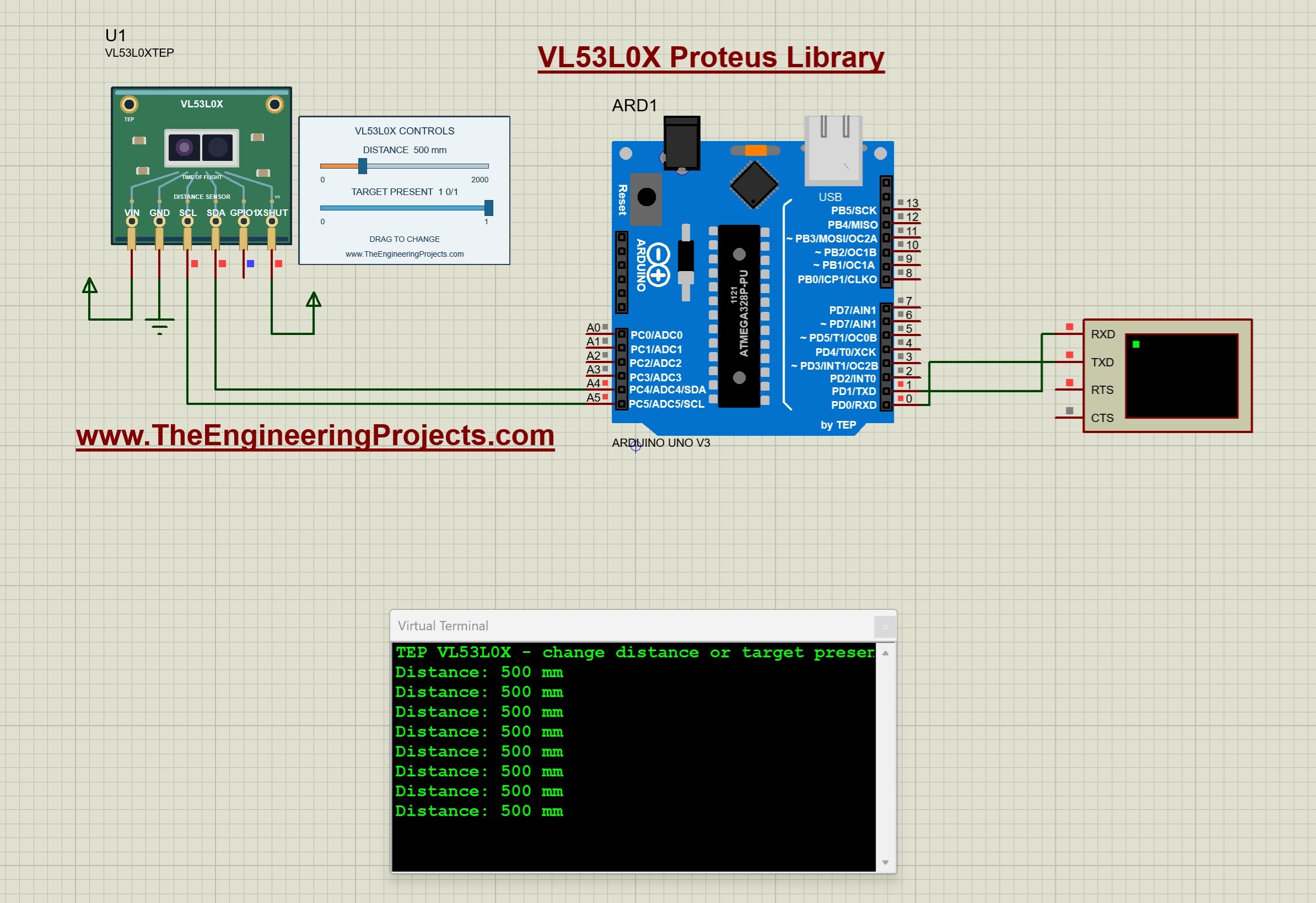
This tutorial uses the corrected V1.0.1 package and the TEP Arduino UNO V3.0 at 16 MHz. The supplied project has documented run checks in Proteus 8.5 SP0. The featured screenshot below shows the initial 500 mm distance with a target present. Let us first understand what that reading means.
What Is the VL53L0X Distance Sensor?
The VL53L0X is a time-of-flight distance sensor. The physical device uses emitted light and its return from a target to support ranging. ST's VL53L0X documentation describes the optical device and its integrated ranging functions.
The Arduino communicates with the sensor over I2C and receives a digital distance result. It does not time an external echo pulse as it would in a typical ultrasonic-sensor example. SDA and SCL carry commands and measurement data between the controller and the device.
Our Proteus component is named VL53L0XTEP. Its distance slider supplies the simulated measurement input, while TARGET PRESENT selects whether a usable target is available. Moving a drawing around the schematic or putting an object in front of your monitor does not change these inputs.
The distinction matters when testing an application. A numeric distance and a missing target are different states. Your program should not interpret an unavailable result as an object at zero distance, because zero may otherwise activate a near-object condition.
Download the VL53L0X Library for Proteus
First of all, download the V1.0.1 archive using the button below. Extract the complete folder before opening the simulation, and keep its supporting files together.
Download VL53L0X Proteus Library V1.0.1 and Arduino SimulationThis package includes a corrected project for the sensor's pin mapping. If you have an earlier test folder, open the project from the newly extracted V1.0.1 folder. Replacing only the DLL while continuing to open an older project does not apply the project correction.
| Folder | Purpose |
|---|---|
| Proteus Library Files | TEPVL53L0X.LIB and the TEP Arduino UNO V3.0 LIB/IDX files. |
| Proteus Model Files | TEPVL53L0X.DLL, the functional ranging model. |
| Proteus Simulation | The corrected VL53L0X-ArduinoUnoV3.pdsprj project, VL53L0X_Demo.hex and a local sensor DLL. |
| Arduino Code | The sketch, Pololu driver sources, AVR core archive and firmware rebuild script. |
| Model Source and Documentation | Implementation, supported behavior, runtime-check notes and third-party notices. |
The LIB defines the component, the DLL provides its simulated behavior, and the Arduino programming library supplies the functions used by the sketch. These are separate installations. Adding the Pololu library to Arduino IDE alone will not add VL53L0XTEP to Proteus.
How to Install the VL53L0X Proteus Library
Save your current work and close Proteus before copying the files. We will install the sensor and its model, then restart the program.
- Open the extracted Proteus Library Files folder.
- Copy
TEPVL53L0X.LIBinto the library directory configured for your Proteus installation. - Add
ArduinoV3TEP.LIBandArduinoV3TEP.IDXif the TEP Arduino UNO V3.0 library is not already installed. - Copy
TEPVL53L0X.DLLfrom Proteus Model Files into your configured Proteus MODELS directory. - Restart Proteus and search for VL53L0XTEP in Pick Devices.
- Open the supplied V1.0.1 circuit for the first experiment.
Library and model paths can differ between installations. Use the folders your copy of Proteus actually searches. The sensor is supplied as a native LIB without a separate sensor IDX in this archive; do not rename another device's index file to create one.
Keep the extra DLL inside the Proteus Simulation folder beside the project. VL53L0X_Demo.hex belongs to the Arduino's Program File property. The sensor itself uses its DLL rather than a separate sensor HEX.
The documented Proteus checks cover the supplied wired project. They do not establish Proteus 7 compatibility or guarantee every custom circuit. The included Uno board is also described in our Arduino Library for Proteus V3.0 tutorial.
VL53L0X Pinout and Arduino Uno Wiring
The six pins along the lower edge are VIN, GND, SCL, SDA, GPIO1 and XSHUT. The printed labels identify the pins; start electrical wires at their exposed endpoints below the board.
| Sensor pin | Connection | Purpose |
|---|---|---|
| VIN | Positive supply rail | Enables the powered digital model. |
| GND | Common ground | Provides the shared reference. |
| SCL | Arduino Uno A5 | I2C clock. |
| SDA | Arduino Uno A4 | I2C data. |
| GPIO1 | Unconnected | The example polls measurement status rather than using this interrupt output. |
| XSHUT | Positive supply rail in the simulation | Keeps the sensor enabled. |
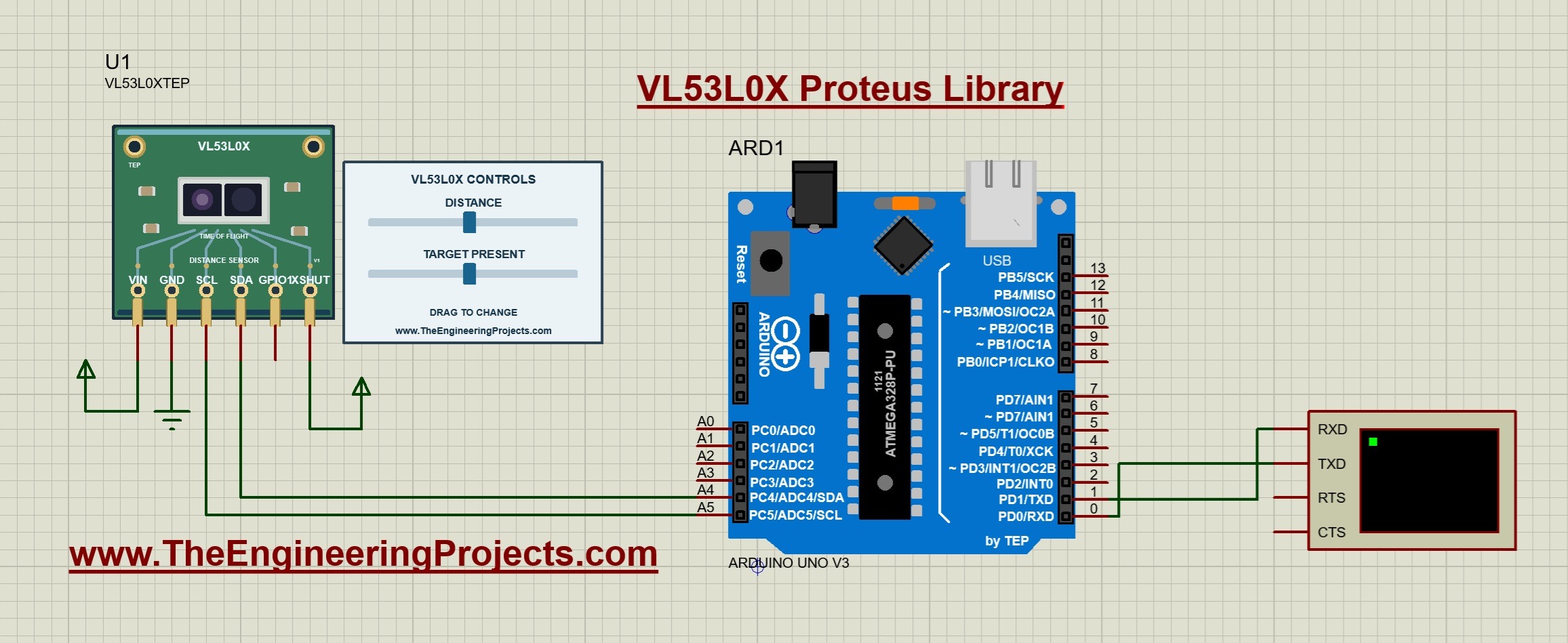
XSHUT is particularly important. Holding it low shuts the device down, so correct SDA and SCL wiring alone will not make initialization succeed. In the supplied circuit, XSHUT is held high continuously.
Connect Arduino D1/TX to Virtual Terminal RXD and select 9600 baud, eight data bits, no parity and one stop bit. The return serial wire to D0/RX is shown, but the sketch does not require incoming commands. Check that the Uno uses a 16 MHz clock.
The circuit uses the AVR Wire implementation's internal pull-ups in this digital simulation. A physical breakout needs its own voltage and pull-up checks, especially for XSHUT and GPIO1. The simulated positive rail does not establish that every exposed pin on a real module accepts the Uno's supply voltage.
Run the Distance-Sensor Simulation
- Open
Proteus Simulation/VL53L0X-ArduinoUnoV3.pdsprjfrom the V1.0.1 download. - Keep VL53L0X_Demo.hex and TEPVL53L0X.DLL beside that project.
- Check the Arduino Program File, 16 MHz clock and 9600 baud terminal.
- Confirm that XSHUT is high, then press Run.
- Open the terminal window and confirm repeated readings of approximately 500 mm.
The documented defaults are a distance of 500 mm and TARGET PRESENT set to 1. The running screenshot shows those conditions and matching terminal output. Let a few lines appear before moving the controls.
Now move the distance handle to the right and wait for the newest reading. Move it left to reduce the distance. The V1.0.1 runtime notes record a successful change from 500 mm to 1432 mm, followed by a no-target test and restoration of the target.
For the second test, move TARGET PRESENT fully left to 0. The terminal should print No target detected. Move it fully right to 1 and the selected distance should return. This tests a different branch of the firmware from ordinary distance changes.
Understand the Distance and Target Controls
| Property | Range | Default |
|---|---|---|
| DISTANCE | 0 to 2000 mm | 500 mm |
| TARGET | 0 or 1 | 1, target present |
Drag a blue handle or click its track during simulation. To enter an exact starting value, stop the run and edit DISTANCE or TARGET in the component properties. Restarting restores those saved properties rather than the last dragged position.
The distance range describes this model's adjustable input. It does not guarantee that a physical VL53L0X produces equally accurate results across all targets and lighting conditions. The model does not simulate reflectivity, ambient light or optical mounting effects.
A target at the lower slider endpoint is still a present target. Removing it with TARGET is different. Keeping those cases separate is useful when testing a display, an obstacle indicator or a state machine.
Arduino Code for the VL53L0X Simulation
The following sketch is the exact code included in the package. It uses the Pololu VL53L0X library, version 1.3.1 in the supplied sources. The library handles initialization and ranging transactions over I2C.
#include <Wire.h>
#include <VL53L0X.h>
VL53L0X sensor;
bool ready=false;
void setup() {
  Serial.begin(9600); Wire.begin(); Wire.setWireTimeout(25000,true);
  sensor.setTimeout(500); ready=sensor.init();
  if(!ready) { Serial.println(F("VL53L0X not found. Check power, SDA, SCL and XSHUT/VCC.")); return; }
  sensor.startContinuous(50);
  Serial.println(F("TEP VL53L0X - change distance or target presence."));
}
void loop() {
  if(ready) {
    uint16_t mm=sensor.readRangeContinuousMillimeters();
    if(sensor.timeoutOccurred()) Serial.println(F("Ranging timeout."));
    else if(mm>=8190) Serial.println(F("No target detected."));
    else { Serial.print(F("Distance: ")); Serial.print(mm); Serial.println(F(" mm")); }
  }
  delay(250);
}
Initialize Communication and Set Timeouts
Serial.begin starts the terminal output at 9600 baud, and Wire.begin initializes I2C. The Wire timeout is 25,000 microseconds, or 25 ms, with reset enabled after a timeout. This bounds a low-level bus wait.
The call sensor.setTimeout(500) sets a separate 500 ms timeout for the sensor driver's waiting operations. These two timeout settings have different units and purposes. Neither specifies the distance to be measured.
The result of sensor.init is saved in ready. If initialization fails, the sketch prints the connections to check and does not start normal ranging. After correcting power, wiring or XSHUT, restart the simulation so initialization runs again.
Start Continuous Ranging
The call sensor.startContinuous(50) requests timed continuous ranging with a 50 ms period. It is not a 50 mm limit. Measurement execution must still fit the configuration, and the functional model's conversion timing is approximate.
Inside loop, readRangeContinuousMillimeters obtains a result in millimeters. The sketch first checks whether a timeout occurred, then tests for the model's no-target result, and only then prints an ordinary numeric distance.
The loop also waits 250 ms between iterations. Its display rate is therefore roughly four updates per second, with additional time for reading and printing. A 50 ms ranging period does not imply that this sketch prints twenty lines per second.
Distance Calculations and Units
The driver already returns millimeters, so there is no raw-scale division needed for the displayed value. To convert units, use centimeters = millimeters / 10 and meters = millimeters / 1000. The default 500 mm is therefore 50 cm or 0.5 m.
Use floating-point division when fractional output matters. For example, 1432 / 10.0 gives 143.2 cm, while integer division by 10 discards the fractional part. Decide how many decimal places your display needs without confusing formatting with physical accuracy.
The Time-of-Flight Principle
A simple round-trip distance relationship is distance = speed of light × travel time / 2. The division by two accounts for the outgoing and returning path. For a 0.5 m target and a light speed of approximately 299792458 meters per second, the ideal round-trip time is about 3.34 nanoseconds.
This calculation explains the principle, not the timing performed by the Arduino sketch. The sensor handles its internal optical ranging process. The 50 ms period is an acquisition scheduling value and must not be substituted for the light's travel time.
Build a Simple Distance Threshold
As a follow-up exercise, display a near-object message below 200 mm and clear it above 250 mm. Between those values, retain the previous state. The 50 mm separation introduces hysteresis and avoids repeatedly changing state around one threshold.
Check measurement validity before applying the thresholds. Decide separately what the application should show when no target is available or a timeout occurs. An old distance may be useful as history, but it should not be displayed as though it were a fresh valid measurement.
No Target, Timeout and Initialization Failure
| Condition | Meaning in this demonstration | Response |
|---|---|---|
| Initialization failure | The driver's startup sequence did not complete. | Check power, SDA, SCL and XSHUT, then restart. |
| Ranging timeout | A driver wait exceeded its configured limit. | Inspect communication and measurement configuration. |
| No target detected | The model completed a result indicating no usable target. | Restore TARGET PRESENT or handle the unavailable state in your application. |
For the no-target condition, this model returns the marker 8190. The supplied sketch treats values at or above that marker as unavailable instead of displaying them as a distance of 8.19 meters. That threshold is part of this demonstration's handling; it is not an extension of the slider's 2000 mm range.
The timeout check comes first because a failed wait should not be interpreted as an ordinary distance. When adapting the example, retain that ordering and review the status information available from the driver you choose.
Address Selection and Multiple Sensors
The default seven-bit I2C address is 0x29. The model supports changing it through I2C, and Pololu's setAddress function updates the address used by the driver. This is different from sensors that select between two fixed addresses using a dedicated address pin.
For a multi-sensor experiment, start with all devices held in shutdown, enable one, initialize it and assign a unique address before enabling the next. Each device needs its own controlled XSHUT connection and driver object. The supplied single-sensor circuit ties XSHUT high, so it must be adapted for that sequence.
Resetting or shutting down the modeled device restores its default address. Repeat address assignment after a fresh startup. Get the single-sensor example working first; the provided HEX does not implement a multi-device setup.
Compile and Test Your Own Changes
- Open
Arduino Code/VL53L0X_Demo/VL53L0X_Demo.inoin Arduino IDE. - Select Arduino Uno and the documented Arduino AVR Boards 1.8.6 core.
- Install the supplied Pololu VL53L0X library from Arduino Code/libraries.
- Compile and export the application HEX after editing.
- Select the new HEX in the Uno's Program File property and restart the simulation.
The download also includes a portable rebuild script and AVR core sources. Its README describes the compiler paths needed for that route. Keep a copy of the supplied project before changing the firmware or wiring.
A useful test sequence is 500 mm, a shorter distance, a longer distance, target absent, target restored and finally a restart. Record the expected value and observed message at each step. This checks numeric updates, unavailable-state handling and restoration of the initial properties.
Common Problems and Their Solutions
| Problem | What to check |
|---|---|
| Device missing from Pick Devices. | Check TEPVL53L0X.LIB in the active library path and restart Proteus. |
| Missing VIN, XSHUT or GPIO1 errors in an older project. | Open the corrected project from the V1.0.1 archive. |
| The model cannot load. | Check TEPVL53L0X.DLL in MODELS and beside the supplied project. |
| Sensor not found. | Check common ground, SDA/A4, SCL/A5, power and XSHUT high. |
| Only no-target messages appear. | Set TARGET PRESENT to 1; changing DISTANCE alone does not restore a missing target. |
| Terminal output is blank or unreadable. | Check the HEX path, D1/TX to RXD, 16 MHz clock and 9600 baud. |
| Source edits do not change the result. | Compile a new HEX and update the Arduino's Program File. |
Practical Review and FAQs
The library is useful for learning initialization, ranging, timeouts, address assignment and application logic around valid or unavailable data. It models single and continuous ranging, relevant status behavior and XSHUT. Optical calibration, target reflectivity, ambient light and physical range error are outside its scope.
Do I Need to Connect GPIO1?
No. The supplied driver polls status over I2C. GPIO1 is left unconnected in this example.
Is the Distance Slider a Real Optical Target?
No. It supplies a deterministic input to the digital model. The simulation does not trace light through objects drawn on the schematic.
Why Does the Terminal Show 500 mm After Restarting?
Restarting restores the configured DISTANCE property. Edit that property while stopped if you want a different initial value.
Does V1.0.1 Require Different Arduino Code?
The release notes identify a corrected project pin mapping; the library DLL, sketch and HEX remain unchanged. Use the complete updated project instead of mixing it with the older test circuit.
Can I Run the Example Without Arduino IDE?
Yes. The included HEX is ready for the supplied Uno circuit. A compiler is required when you change the sketch.
That completes our VL53L0X Proteus Library tutorial. Start with the supplied circuit, test both controls and keep distance values separate from unavailable results. Once the basic example is clear, extend it with your own display or threshold logic and share your questions in the comments.