Hello friends, I hope you all are doing great. Today, I am going to share the new Infrared Sensor Library for Proteus V2.0. It simulates the FC-51 IR obstacle sensor, the small blue board with a clear IR LED and a dark photodiode at one end, which tells your Arduino with a single pin whether something is in front of it. With this Infrared Sensor Library for Proteus, you place the object yourself (its distance, its colour, indoor light or sunlight, even a waving hand), and your Arduino reads the OUT pin exactly as it reads the real module.
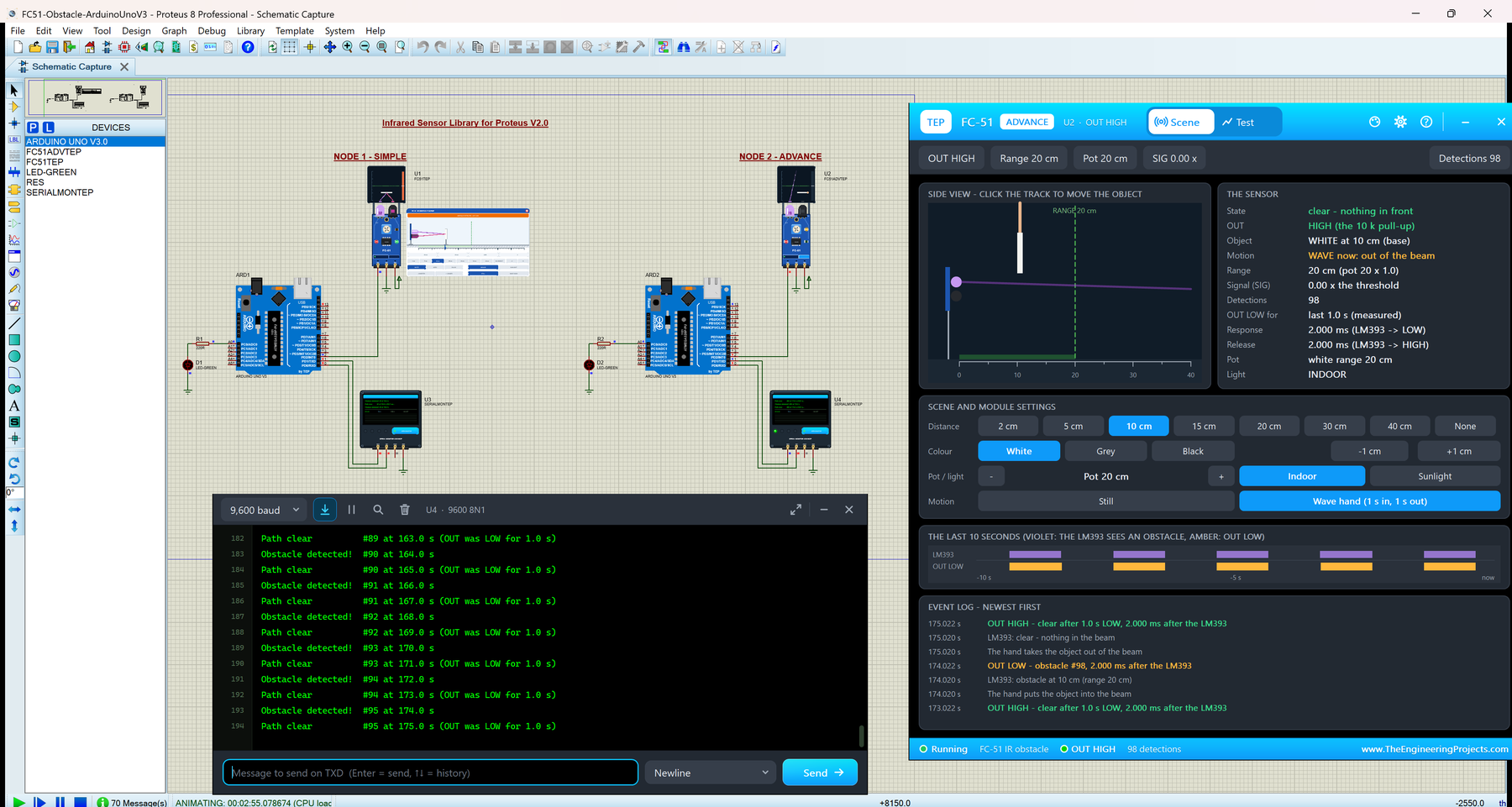
We have shared infrared sensor libraries for Proteus before, and version 2.0 is a big step forward. You now get two devices: FC-51 Simple, with an animated scene panel on the schematic, and FC-51 Advance, with a pop-up window, an event log and four measured IR sensor test tools. The board itself has a live IR VIEW screen, and the new FC-51 Arduino Proteus demo runs on two Arduino UNOs with our TEP Serial Monitor, shown here in its compact Simple interface.
NOTICE: This library is very special to our team. Our FC-51 model has the whole decision of the real module: the IR reflection against the threshold of the pot, dark objects seen much closer, the false trigger in sunlight, and the response delay of the LM393 with its filter. On top of that, it keeps an event log and measures every edge on the OUT pin. It took our team a lot of hard work, many test runs and many design changes. Your feedback is the fuel that keeps us going, so please tell us what you think in the comments below or in the Infrared Sensor Library board of our forum. And if our free libraries help you, you can buy us a coffee. So, let's get started with the Infrared Sensor Library for Proteus:
What is an IR Obstacle Sensor (FC-51)?
The FC-51 is the best-known IR obstacle avoidance sensor module; you will also find it sold as HW-201 or in the "MH sensor" series. It is a small blue board, about 31 x 14 mm, and it works by reflection. The clear IR LED shines invisible infrared light forward. When an object is close enough, part of that light bounces back into the dark IR photodiode next to it. An LM393 comparator compares the photodiode's signal with a level set by the blue potentiometer (the pot) and switches the OUT pin.
OUT is a plain digital signal: HIGH while the path is clear (the board has its own 10 k pull-up resistor) and LOW while an obstacle is in front. The green OBS LED on the board lights at the same time. That is why the FC-51 is so popular in obstacle-avoiding robot cars, object counters and simple proximity switches: one wire, no Arduino library, just digitalRead().
The FC-51 at a Glance
| Feature | Value |
|---|---|
| Sensing | Reflected infrared light: an IR LED and an IR photodiode side by side |
| Output | OUT, digital: LOW = obstacle, HIGH = clear (10 k pull-up on the board) |
| Comparator | LM393 |
| Range | About 2 to 30 cm for a white object, set with the pot (clockwise = longer) |
| Detection angle | About 35° |
| LEDs | PWR (red, the supply) and OBS (green, lit while OUT is LOW) |
| Pins | OUT, GND, VCC on a 3-pin header |
| Supply | 3.3 to 5 V, about 20 mA |
| Board | About 31 x 14 mm, one mounting hole |
FC-51 Terms You Will See in This Article
| Term | Meaning |
|---|---|
| IR LED | The infrared emitter (the clear dome); its light is invisible to your eye |
| Photodiode | The infrared receiver (the dark dome); its signal grows with the reflected light |
| LM393 | A comparator chip: it compares two voltages and switches OUT |
| Pot / sensitivity | The blue trimmer potentiometer; in our model its setting is the range for a white object |
| Range / threshold | The distance up to which the reflection is strong enough for a detection |
| Hysteresis | A small extra distance the object must move before OUT goes HIGH again |
| Chatter | OUT flipping between LOW and HIGH while an object sits right at the threshold |
| Debounce | Software that accepts a change only after it has lasted some time |
| Response delay | The time from the LM393's decision to the change on OUT |
| Event log | The Advance pop-up's list of everything the model did, with the simulation time |
How Our FC-51 Model Decides
The Detection Rule
Our model keeps one simple rule: OUT goes LOW when the object is in the beam at a distance up to the range, and the range is pot x colour factor x light factor. The pot setting itself is the range for a white object, from 2 to 30 cm (20 cm at the start); the panel and the board's pot change it in 2 cm steps.
| Setting | Factor | Range at pot 20 cm |
|---|---|---|
| WHITE object | 1.0 | 20 cm |
| GREY object | 0.55 | 11 cm |
| BLACK object | 0.2 | 4 cm |
| INDOOR light | 1.0 | as above |
| SUNLIGHT | 0.6 (and a false trigger with the pot above 15 cm) | see below |
Dark objects absorb infrared, so they are seen much closer. The black factor 0.2 comes from one tutorial (black detected at 5 cm where white triggered at 25 cm); the grey factor 0.55 and the sunlight factor 0.6 are our own estimates, not datasheet values. Sunlight also has a second effect: with the pot above 15 cm, the sun's infrared alone crosses the threshold, and OUT goes LOW with nothing in front, a false detection.
Hysteresis and the Response Delay
A real FC-51 has no hysteresis, so OUT can chatter right at a long threshold. Our model adds a small one: once an object is detected, it must move beyond the range plus 0.3 cm or 3 % of the range (the larger of the two) before OUT goes HIGH again. OUT also follows the LM393 only after the RESPONSE delay, 2 ms at the start (the only number we found, from one product listing). A flip of the LM393 that reverses within that delay never reaches OUT: it is filtered.
What's New in Infrared Sensor Library for Proteus V2.0
If you used one of our earlier infrared sensor libraries, here is what version 2.0 brings:
- Two devices in
TEPFC51.LIB: FC-51 Simple (FC51TEP) with the scene panel on the sheet, and FC-51 Advance (FC51ADVTEP) with a pop-up window. - A redrawn, live board: the blue FC-51, a little longer and closer to the real 31 x 14 mm, with the module's own PWR and OBS LEDs, a TEP EDGE LED and the animated IR VIEW screen above the IR pair.
- An event log and measured values: every LM393 decision and OUT edge with its measured delay, how long OUT was LOW, filtered flips and scene changes; the Simulation Log adds the LOW time too.
- A distance exactly on the range always counts (floating point could make 8.4 cm miss a range of 8.4 cm).
- Four measured test tools on the Advance: Colour sweep, Response time, Pot check and Sunlight test.
- A two-UNO demo with the TEP Serial Monitor instead of the Virtual Terminal, and a sketch with the obstacle number, the time, the LOW time and the commands HELP, STATUS, RESET, WATCH and DEBOUNCE.
- A lighter simulation: the panels redraw 12.5 times a second, and only the parts that changed.
- Lighter package: about 1.45 MB, without the C++ source code.
Infrared Sensor Library for Proteus: Simple vs Advance
Both devices run the same model with the same properties; only the panel differs:
| Feature | Simple | Advance |
|---|---|---|
| Full FC-51 model (pot, colour, sunlight, hysteresis, response delay, WAVE HAND) | ✔ | ✔ |
| Blue FC-51 board: PWR / OBS / EDGE LEDs and the IR VIEW screen | ✔ | ✔ |
| IR OBSTACLE SCENE panel on the schematic (red X closes it, PANEL opens it) | ✔ | ✘ |
| Pop-up window you can move, resize and minimise | ✘ | ✔ |
| Scene page: THE SENSOR card, the last 10 seconds and the event log | ✘ | ✔ |
| Colour sweep, Response time, Pot check and Sunlight test | ✘ | ✔ |
| TEP Dark / Light theme, text size, Help page with Copy diagnostics | ✘ | ✔ |
| PANEL property (the panel open or closed at Run) | ✔ | ✘ |
Choose Simple to keep the scene beside your circuit, and Advance when your sheet is full or you want hard numbers. The demo has one of each.
Download Infrared Sensor Library for Proteus
Click the button below to download Infrared-Sensor-Library-for-Proteus-v2.0.zip (about 1.45 MB, without the C++ source code):
Infrared Sensor Library for Proteus V2.0- README.txt: a detailed guide to the files, the wiring, the model, the test tools and real hardware.
- Proteus Library Files:
TEPFC51.LIB(both devices),TEPSERIALMON.LIBand our Arduino UNO libraryArduinoV3TEP.LIB/ArduinoV3TEP.IDX. - Proteus Model Files:
TEPFC51.DLLandTEPSERIALMON.DLL. - Proteus Simulation:
FC51-Obstacle-ArduinoUnoV3.pdsprj,FC51_Obstacle.hex(both UNOs run it) and copies of both DLLs. - Arduino Code:
FC51_Obstacle.ino, the demo sketch. It needs no Arduino library.
No Proteus yet? Read How to Download and Install Proteus 7 and 8. New to libraries? Follow How to Install a New Library in Proteus.
How to Install Infrared Sensor Library for Proteus
- Close Proteus and extract the whole zip file.
- Copy the four files from Proteus Library Files into the LIBRARY folder, usually
C:\Program Files (x86)\Labcenter Electronics\Proteus 8 Professional\LIBRARY(on some PCsC:\ProgramData\Labcenter Electronics\Proteus 8 Professional\LIBRARY; use the folder that already holds the .LIB files of Proteus). - Copy
TEPFC51.DLLandTEPSERIALMON.DLLinto the MODELS folder. - Start Proteus, press P and search for FC-51 (or "IR Obstacle"). You get the Simple and the Advance device, in the category Sensors > Proximity.
Updating from an earlier version? Replace its LIB and DLL, and delete TEPFC51.IDX if there is one in the LIBRARY folder. Tested in Proteus 8.5; Proteus 7 is not supported.
The FC-51 Board in Proteus
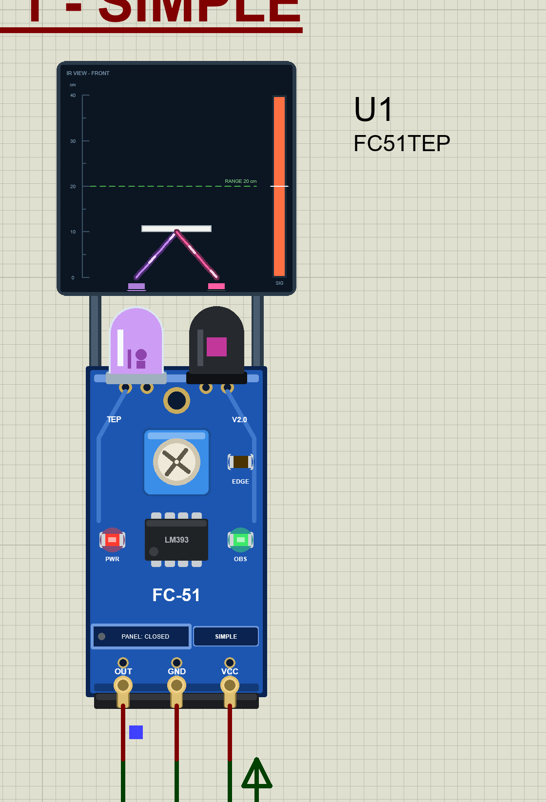
We drew the sensor as a clean TEP board in the blue of the real module: the clear IR LED and the dark photodiode standing over the top edge, the mounting hole, the blue pot, the LM393, the "FC-51" print and the OUT GND VCC header at the bottom. Here is U1, the Simple device, right after Run:
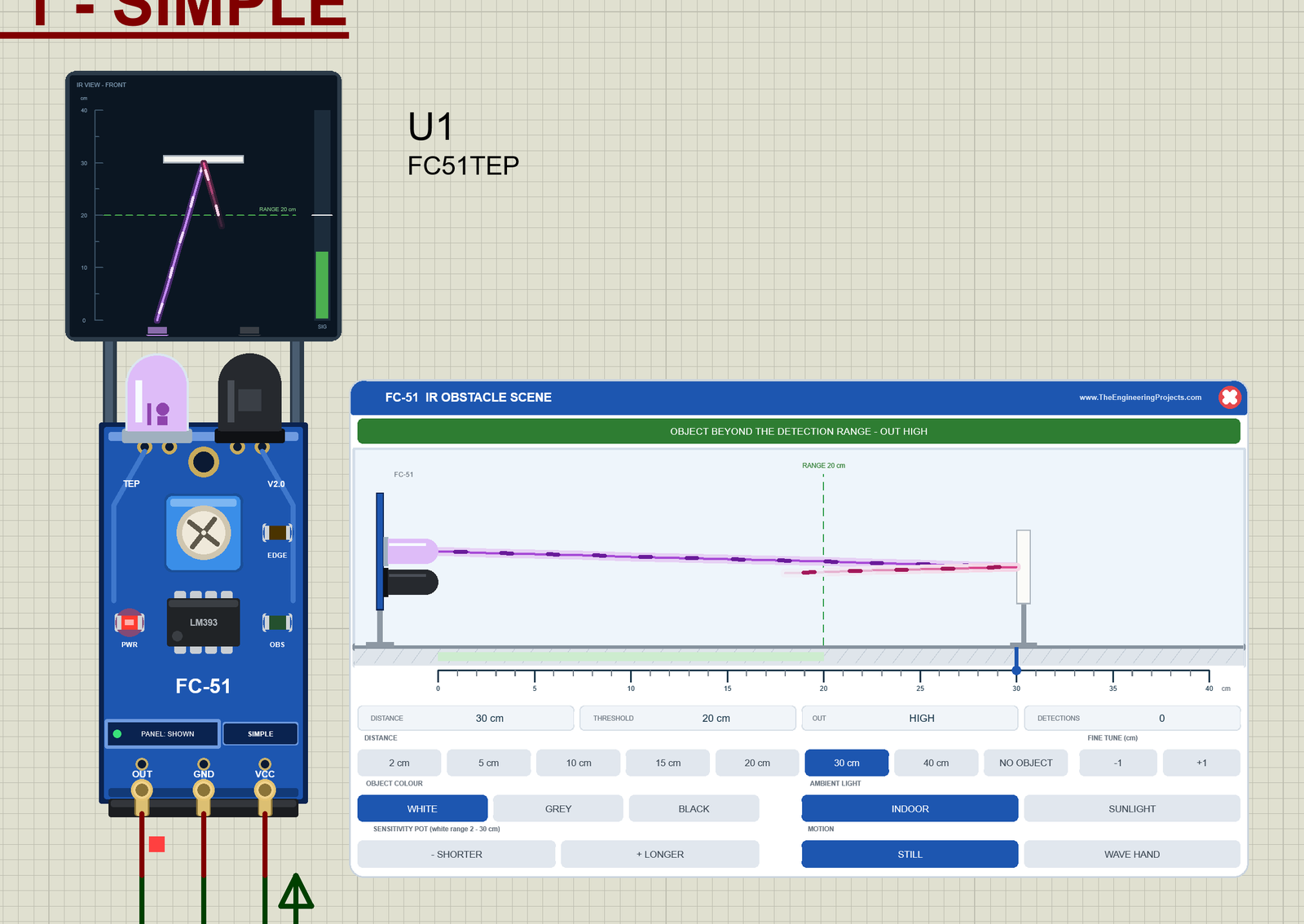
The start values put a white object at 30 cm while the range is 20 cm. So the panel's green banner says "OBJECT BEYOND THE DETECTION RANGE - OUT HIGH", the readouts show DISTANCE 30 cm, THRESHOLD 20 cm, OUT HIGH and DETECTIONS 0, and only the red PWR LED is lit. The small red square on the OUT wire is Proteus's own logic probe: red for HIGH, blue for LOW.
The IR VIEW Screen
Above the IR pair, on two posts, sits the IR VIEW - FRONT screen. It shows what the sensor looks at, on a 0 to 40 cm scale:
- The beam: the violet IR light going up from the IR LED.
- The object: a card at its distance, in its colour; with WAVE HAND, a hand holds it.
- The reflection: the pink light back to the photodiode, as strong as the colour reflects. At 30 cm it fades out before it reaches the sensor.
- The RANGE line: the green dashed line at the current range.
- The sun: it appears in SUNLIGHT, with red rays when it fools the sensor.
- The SIG meter: the bar on the right, the LM393's input against its threshold (the white mark). At 30 cm the bar stays green, below the mark.
Pinout
The three pins keep the order of the real module, OUT GND VCC from left to right:
| Pin | What it does | Demo connection |
|---|---|---|
| OUT | Digital output: LOW = obstacle, HIGH = clear (the 10 k pull-up) | Arduino D2 |
| GND | Ground | Ground terminal |
| VCC | Power | Supply terminal |
LEDs and Indicators
| Indicator | What it shows |
|---|---|
| PWR LED (red) | Lit while the board has power |
| OBS LED (green) | Lit while OUT is LOW (an obstacle) |
| EDGE LED (amber) | Lights for 0.3 s on every change of OUT, so even a 2 ms pulse is visible |
| IR LED (clear dome) | Glows and pulses violet while the board has power |
| Photodiode (dark dome) | Its core lights magenta while it sees the reflection (or the sun) |
| Blue pot | Its rotor turns with the sensitivity; click its left half for -2 cm, its right half for +2 cm |
| IR VIEW screen | The beam, the object, the reflection, the range, the sun and the SIG meter |
| PANEL / OPEN PANEL, SIMPLE / ADVANCE | The panel button and the device badge |
PWR and OBS are the real module's own LEDs. The EDGE LED, the IR VIEW screen, the panel button and the badge are TEP additions: the real FC-51 has only PWR and OBS.
Component Properties
| Property | Meaning | Default |
|---|---|---|
| DISTANCE | The object's distance in cm, 1 to 40, or NONE | 30 |
| COLOUR | WHITE, GREY or BLACK | WHITE |
| SENSITIVITY | The pot: the white-object range in cm, 2 to 30 | 20 |
| AMBIENT | INDOOR or SUNLIGHT | INDOOR |
| MOTION | STILL or WAVE | STILL |
| RESPONSE | The LM393 to OUT delay in ms, 0 to 1000 | 2 |
| PANEL | Simple only: the panel OPEN or CLOSED at Run | OPEN |
A bad value is written to the Simulation Log, and the default is used. Every Run starts again from these properties; the Advance window has its own "open at Run" setting instead of PANEL.
FC-51 Simple: The IR Obstacle Scene on the Sheet
Beside the Simple board sits the FC-51 IR OBSTACLE SCENE panel (on the right of the image above). It is a side view of the sensor and the object, with the controls below it:
| Part | What it does |
|---|---|
| Header, red X | FC-51 IR OBSTACLE SCENE; the X closes the panel |
| Banner | The state in words and colour: NO OBSTACLE, OBJECT BEYOND THE DETECTION RANGE, OBSTACLE DETECTED, FALSE DETECTION - SUNLIGHT IR, or NO POWER |
| Side view | The sensor on the left, the violet beam, the pink reflection, the object, the RANGE line and the green detection zone; click it to move the object |
| Ruler | 0 to 40 cm; click it to move the object too |
| Readouts | DISTANCE, THRESHOLD (the range now), OUT and DETECTIONS |
| DISTANCE row | 2, 5, 10, 15, 20, 30 and 40 cm, NO OBJECT, and FINE TUNE -1 / +1 cm |
| OBJECT COLOUR / AMBIENT LIGHT | WHITE, GREY, BLACK / INDOOR, SUNLIGHT |
| SENSITIVITY POT | - SHORTER and + LONGER: the white range, 2 to 30 cm in 2 cm steps |
| MOTION | STILL, or WAVE HAND (1 s in the beam, 1 s out) |
The active buttons turn dark blue. In the image above, they are 30 cm, WHITE, INDOOR and STILL: the start values.
10 cm: Obstacle Detected
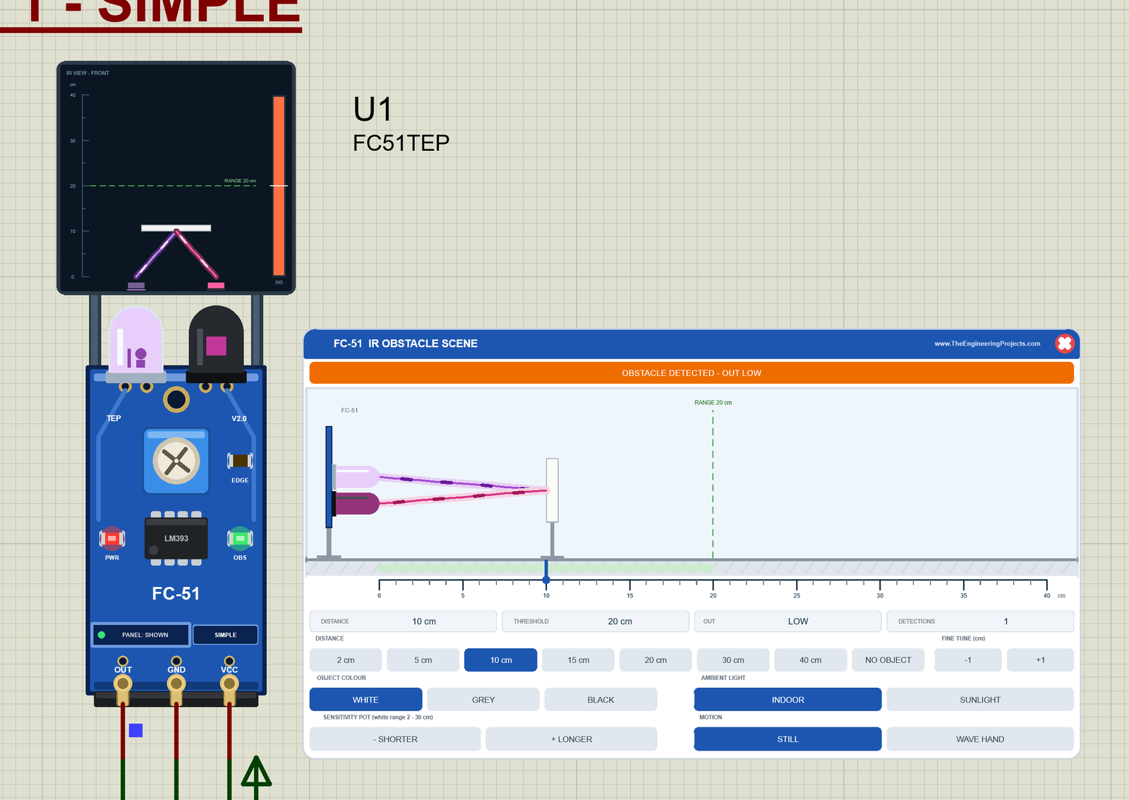
Click 10 cm. The object moves into the green zone, and the reflection now comes all the way back to the photodiode. The SIG bar jumps over the white mark and turns orange, the photodiode's core lights magenta, and 2 ms later OUT goes LOW: the green OBS LED lights, the logic probe turns blue, and the banner says "OBSTACLE DETECTED - OUT LOW". U3 prints "Obstacle detected!"; click NO OBJECT, and it prints "Path clear" with the time OUT was LOW.
GREY and WAVE HAND
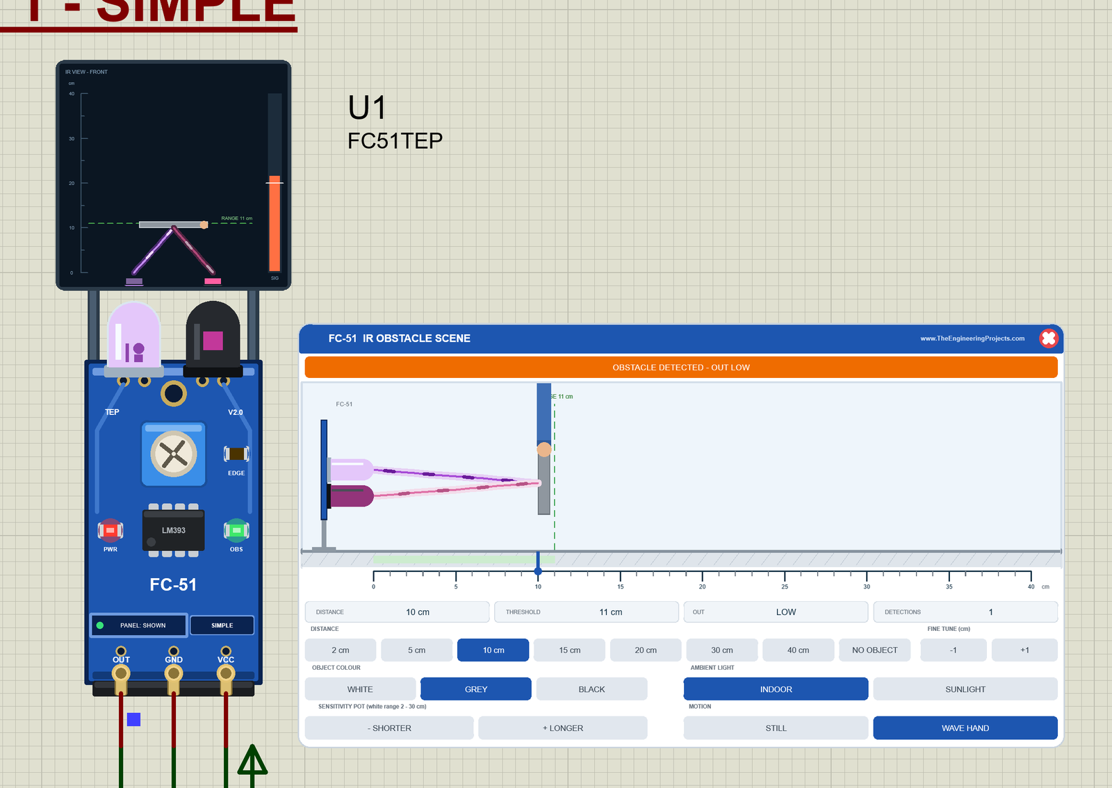
Click GREY. The THRESHOLD readout drops from 20 to 11 cm (0.55 x 20), and the RANGE line moves with it. At 10 cm the grey card is still just inside: OUT stays LOW, and the SIG bar is only a little over the mark. Try 15 cm now: white would be detected there, grey and black would not. That is the real FC-51 lesson: the range depends on the object, not only on the pot.
Then click WAVE HAND. A hand takes the card out of the beam and puts it back every second, and OUT follows: LOW for 1 s, HIGH for 1 s. In the picture, the hand holds the card in the beam.
SUNLIGHT: the False Detection
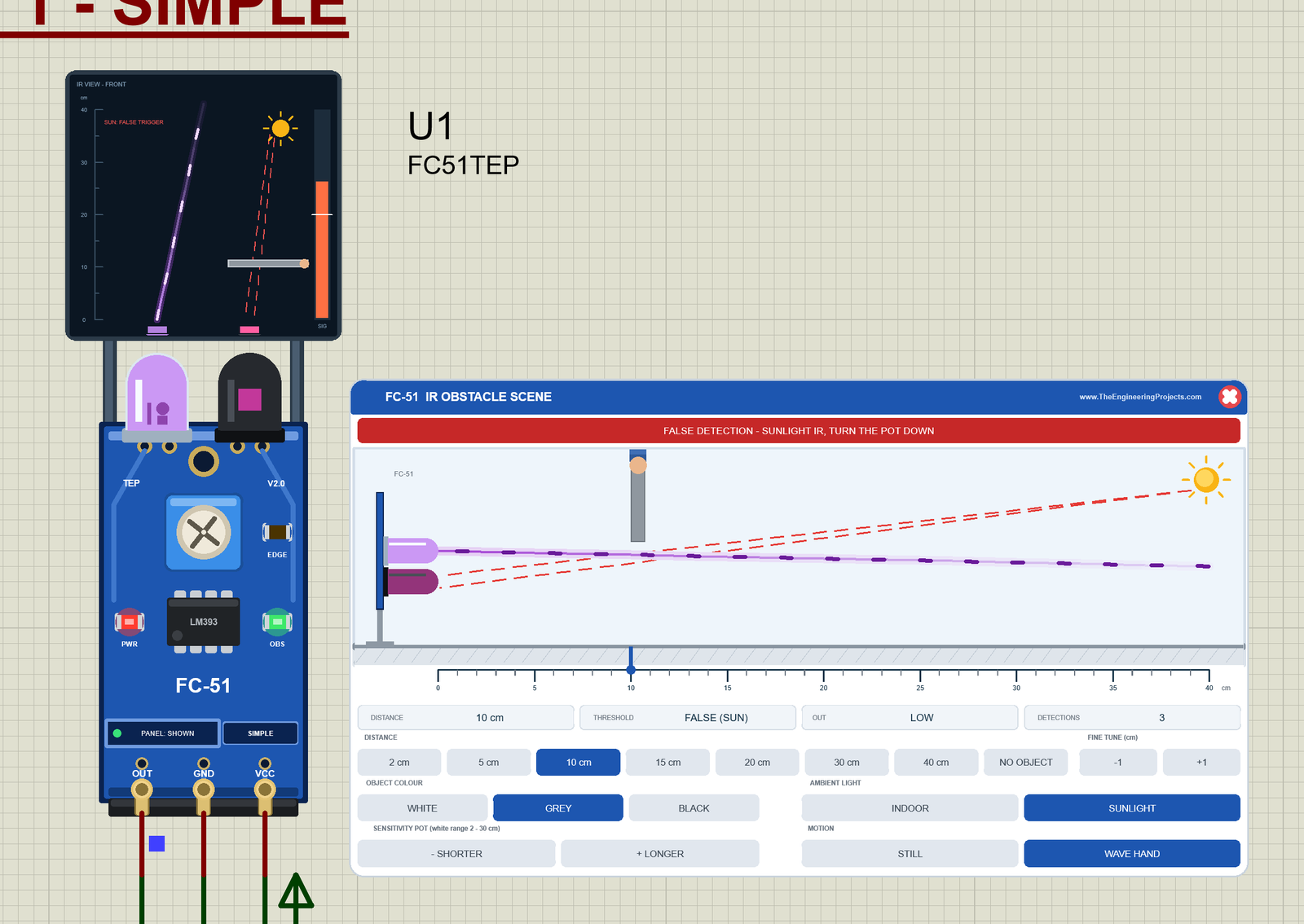
Now click SUNLIGHT with the pot still at 20 cm. The sun appears, and its rays to the photodiode turn red: they fool the sensor. The banner turns red, "FALSE DETECTION - SUNLIGHT IR, TURN THE POT DOWN", THRESHOLD says FALSE (SUN), and the IR VIEW screen writes "SUN: FALSE TRIGGER". Look at the hand: it holds the card out of the beam, but OUT stays LOW anyway.
Click - SHORTER three times (pot 14 cm), and the false trigger goes away. Outdoors, the sensor still works, but with 0.6 x the range. The same happens with a real FC-51 in a sunny window or under some LED lamps.
Closing the Panel
Click the red X: the board button says PANEL: CLOSED and its dot turns grey, while the sensor keeps running. Click the button, and the panel comes back. Here, U1 is back at WHITE, 10 cm and INDOOR:
FC-51 Advance: The Pop-Up Scene Window
The Advance device keeps only the board on the schematic. Here is U2 during WAVE HAND, at the moment the hand holds the card beside the beam:
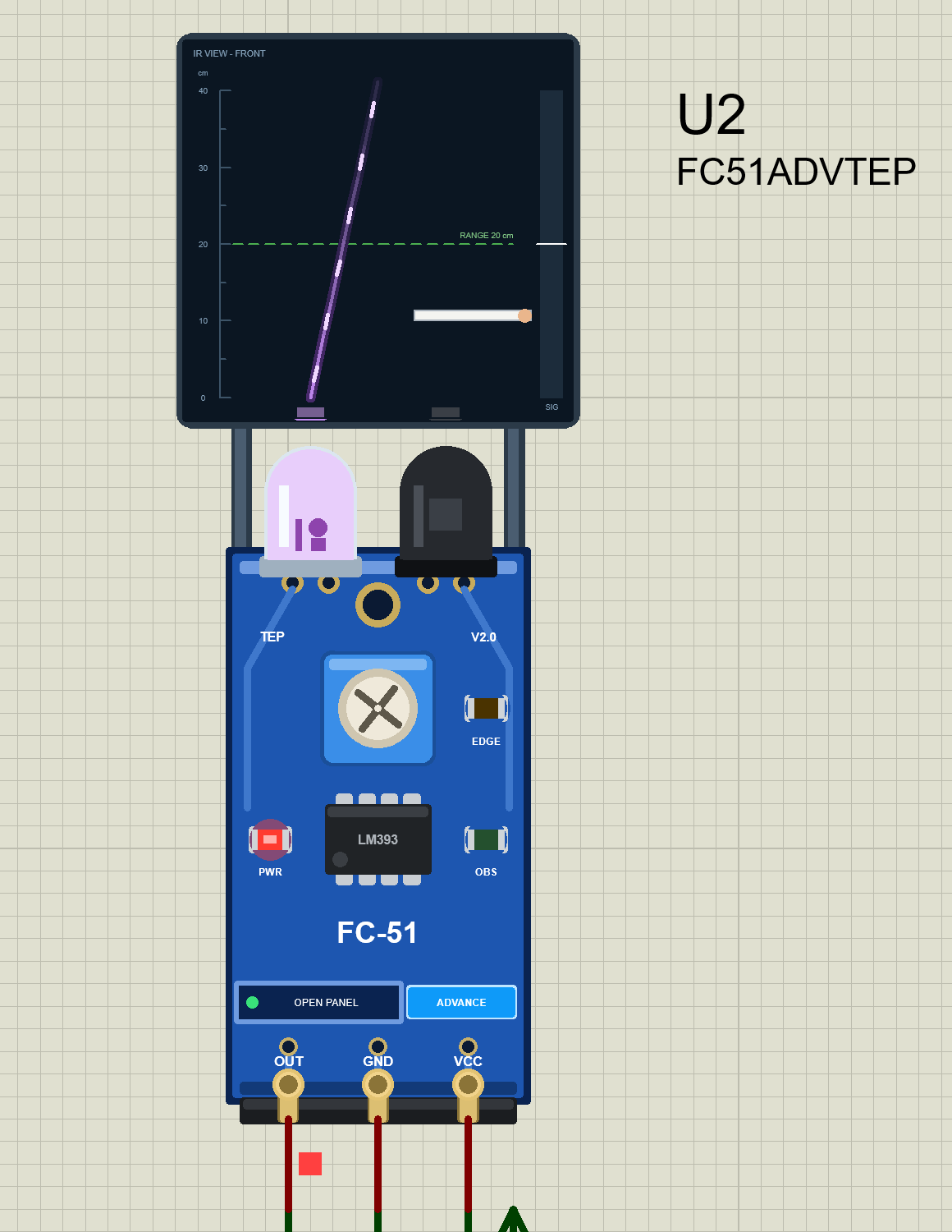
At Run, the "TEP FC-51 Advance" pop-up opens with the look of our TEP Serial Monitor and no Windows title bar: move it by its header, resize or minimise it, and open it again with OPEN PANEL (its dot is green while the window is visible). The header shows the unit and the state (U2 · OUT HIGH, OUT LOW, SUN FALSE, TESTING or NO POWER), the Scene and Test tabs, and the palette (theme), gear (Settings) and ? (Help) icons.
The Scene Page
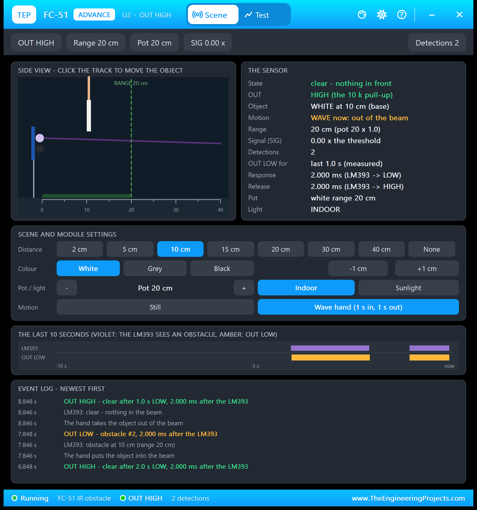
- Toolbar chips: OUT HIGH, Range 20 cm, Pot 20 cm, SIG 0.00 x (the LM393's input as a multiple of its threshold; nothing is in the beam right now) and Detections 2.
- SIDE VIEW: the same scene as on the Simple panel; click the track to move the object. Here the hand has lifted the card out of the beam.
- THE SENSOR: the state, OUT, the object ("WHITE at 10 cm (base)": WAVE moves it, the distance you set stays the base), "WAVE now: out of the beam", the range ("20 cm (pot 20 x 1.0)"), OUT LOW for "last 1.0 s (measured)", and the Response and Release delays from the LM393 to OUT, 2.000 ms each.
- SCENE AND MODULE SETTINGS: the buttons of the Simple panel: distance (2 to 40 cm or None), colour, -1 / +1 cm, the pot with - and +, Indoor / Sunlight, and Still / Wave hand (1 s in, 1 s out).
- THE LAST 10 SECONDS: violet bars while the LM393 sees an obstacle, amber bars while OUT is LOW. The first pair is twice as long as the second.
- EVENT LOG - NEWEST FIRST: every step of the model, with the simulation time.
Here is the event log of this picture, from the bottom (oldest) to the top (newest):
8.848 s   OUT HIGH - clear after 1.0 s LOW, 2.000 ms after the LM393
8.846 s   LM393: clear - nothing in the beam
8.846 s   The hand takes the object out of the beam
7.848 s   OUT LOW - obstacle #2, 2.000 ms after the LM393
7.846 s   LM393: obstacle at 10 cm (range 20 cm)
7.846 s   The hand puts the object into the beam
6.848 s   OUT HIGH - clear after 2.0 s LOW, 2.000 ms after the LM393
At 7.846 s the hand puts the object into the beam, the LM393 decides "obstacle" at once, and OUT follows 2 ms later. One second later, the same happens the other way. Why was the first LOW 2.0 s long? See the Serial Monitor results below.
The Test Page: Four Measured IR Sensor Test Tools
The four tools on the Test tab only move the object and set the colour, the pot or the light; then they read the OUT pin and the model's event log. So every number they show is what OUT really did, timed with the simulation clock. Each tool ends with a bold "Good for:" line and puts the scene back when it ends, and its tiles show "-" until it has measured a value. All results below come from U2.
1. Colour Sweep: How Close Must Each Colour Come?
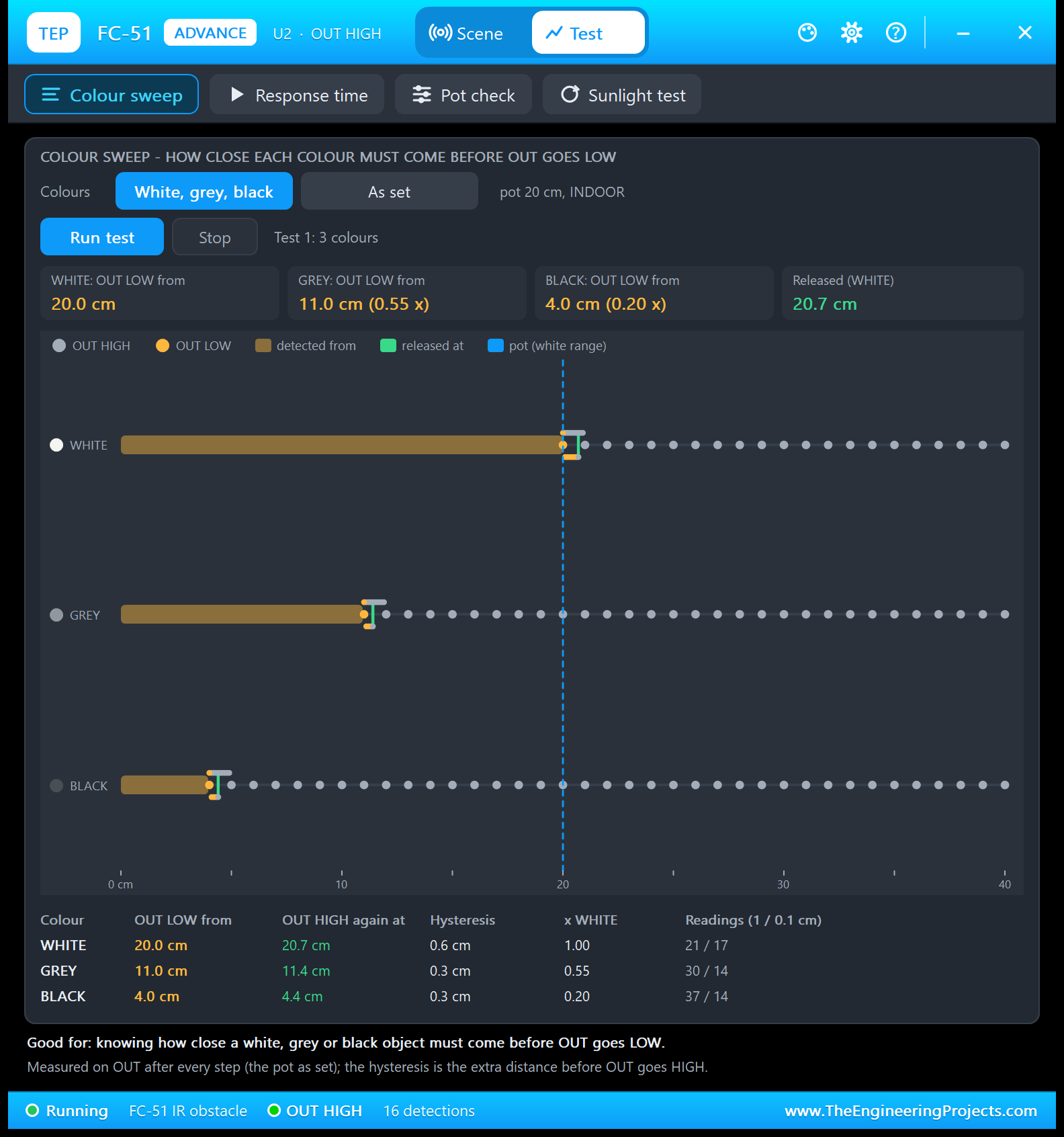
Good for: "knowing how close a white, grey or black object must come before OUT goes LOW." Choose all three colours or the one "As set", and click Run test. Each colour comes from 40 cm in 1 cm steps until OUT is LOW; after a flat lead-in with nothing in front, it comes again in 0.1 cm steps, and then backs out in 0.1 cm steps until OUT is HIGH. OUT is read 20 ms after every step.
| Colour | OUT LOW from | OUT HIGH again at | Hysteresis | x WHITE | Readings (1 / 0.1 cm) |
|---|---|---|---|---|---|
| WHITE | 20.0 cm | 20.7 cm | 0.6 cm | 1.00 | 21 / 17 |
| GREY | 11.0 cm | 11.4 cm | 0.3 cm | 0.55 | 30 / 14 |
| BLACK | 4.0 cm | 4.4 cm | 0.3 cm | 0.20 | 37 / 14 |
A black object must come five times closer than a white one: 4 cm where white triggers at 20 cm. The hysteresis column is the model's release margin: 3 % of 20 cm = 0.6 cm for white, and the 0.3 cm minimum for grey and black (3 % of 11 cm is 0.33 cm). OUT reads HIGH again at the first 0.1 cm step past that margin. The readings show the work: white needed 21 steps of 1 cm (40 down to 20 cm) and 17 of 0.1 cm (10 in, 7 out).
2. Response Time: How Fast Does OUT Follow?
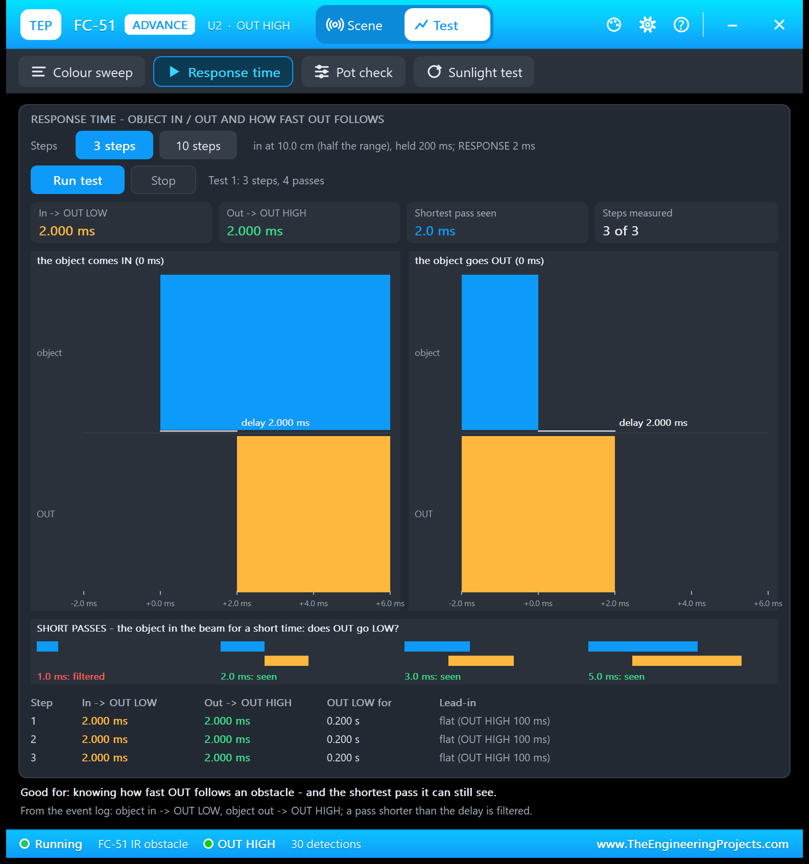
Good for: "knowing how fast OUT follows an obstacle - and the shortest pass it can still see." Choose 3 or 10 steps. Each step starts with a flat lead-in (nothing in front, OUT HIGH for 100 ms), then the object comes in at half the range (10.0 cm here), stays 200 ms and goes out again. The delays come from the event log: object in to OUT LOW, and object out to OUT HIGH.
The result: 2.000 ms in and 2.000 ms out in every step, exactly the RESPONSE property, and OUT LOW for 0.200 s each time (the 200 ms hold). The two zoomed charts show the edges on a -2 to +6 ms scale: the object (blue) moves at 0 ms, and OUT (amber) follows at +2 ms.
Then come four short passes of 0.5, 1, 1.5 and 2.5 times the delay: 1, 2, 3 and 5 ms. The 1.0 ms pass is filtered: the LM393 flips back within the 2 ms delay, so OUT never moves. The 2.0 ms pass just makes it: OUT goes LOW as the object leaves and stays LOW for 2 ms. A pulse that short is invisible on OBS, but the EDGE LED stays lit for 0.3 s.
3. Pot Check: Where Should You Set the Pot?
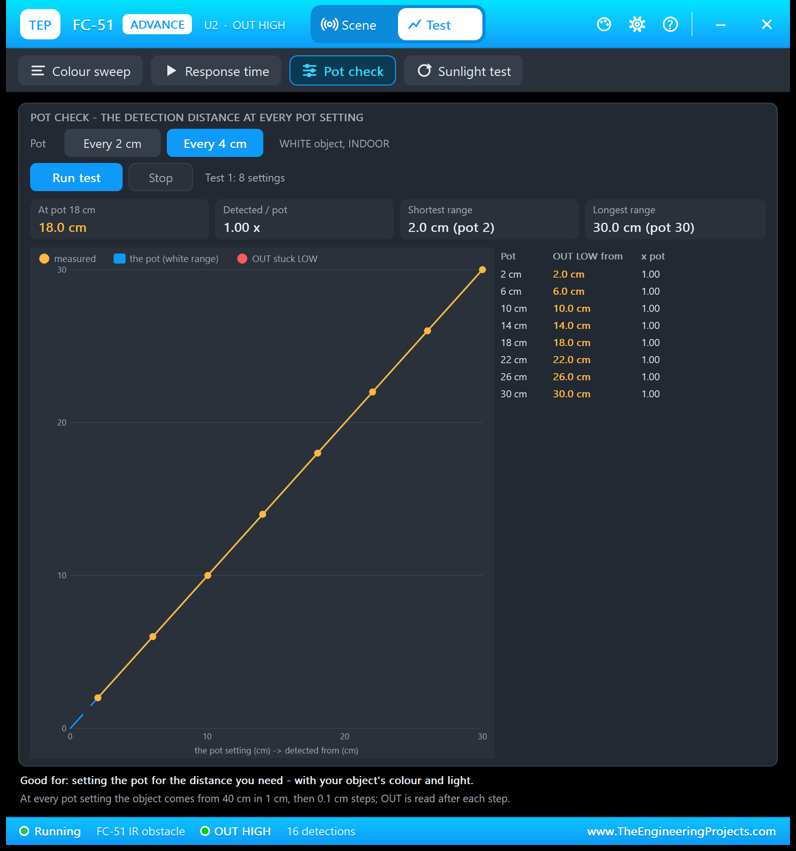
Good for: "setting the pot for the distance you need - with your object's colour and light." Choose every 2 or every 4 cm and click Run test. At every pot setting, the object approaches from 40 cm as in the Colour sweep, with the colour and the light as you set them. Here, every 4 cm with a white object indoors gives 8 settings, from 2.0 cm at pot 2 to 30.0 cm at pot 30, each exactly 1.00 x the pot. The first tile names the measured setting nearest to 20 cm: "At pot 18 cm, 18.0 cm".
Set GREY or SUNLIGHT before the run, and the line gets flatter: 0.55 x for grey, and 0.6 x in sunlight up to pot 14 cm, with red "OUT stuck LOW" dots above it. So the Pot check tells you where to set the pot for your object.
4. Sunlight Test: Why Does It Fail Outdoors?
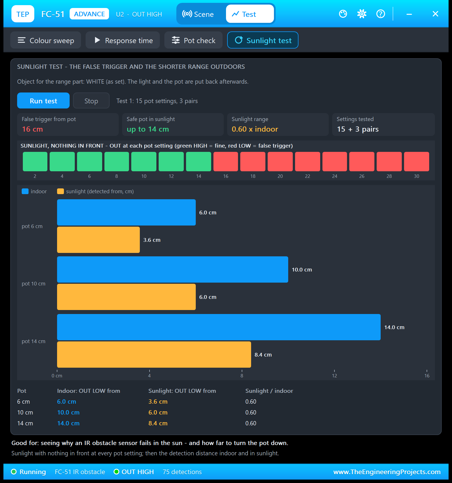
Good for: "seeing why an IR obstacle sensor fails in the sun - and how far to turn the pot down." The tool first sets SUNLIGHT with nothing in front and tries all 15 pot settings from 2 to 30 cm. The strip shows OUT at each one: green (HIGH, fine) up to 14 cm and red (LOW, a false trigger) from 16 cm. Then it measures the detection distance of the white object indoors and in sunlight at pots 6, 10 and 14 cm:
| Pot | Indoor: OUT LOW from | Sunlight: OUT LOW from | Sunlight / indoor |
|---|---|---|---|
| 6 cm | 6.0 cm | 3.6 cm | 0.60 |
| 10 cm | 10.0 cm | 6.0 cm | 0.60 |
| 14 cm | 14.0 cm | 8.4 cm | 0.60 |
So the safe pot in sunlight is up to 14 cm, and there the sensor sees a white object from 8.4 cm. With a real FC-51 the numbers depend on the sun and your board, but the pattern is the same: turn the pot down, or shade the sensor.
Settings and Help
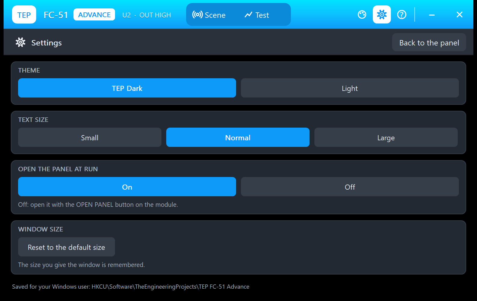
The gear opens Settings: the theme (TEP Dark or Light), the text size, whether the panel opens at Run, and a button that resets the window size. They are saved for your Windows user.
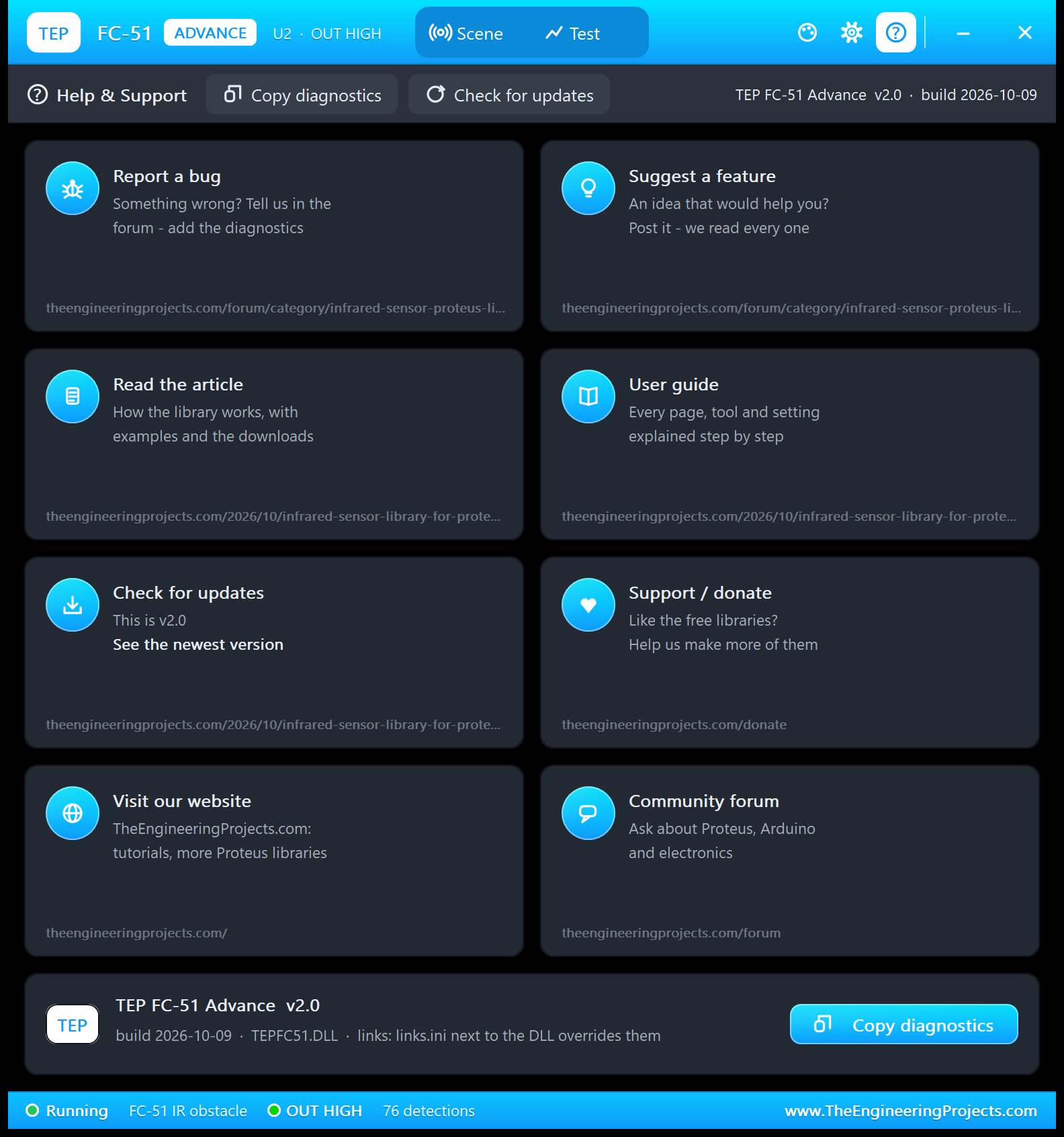
The ? icon opens Help & Support: eight cards with their links (the infrared sensor board of our forum for bugs and ideas, this article, updates, donate, our website and the forum), Check for updates, and Copy diagnostics for a bug report: the sensor, the board, the scene, the measured values, the events and the test results. A links.ini file next to the DLL can change the links.
FC-51 Obstacle Detector with Arduino in Proteus
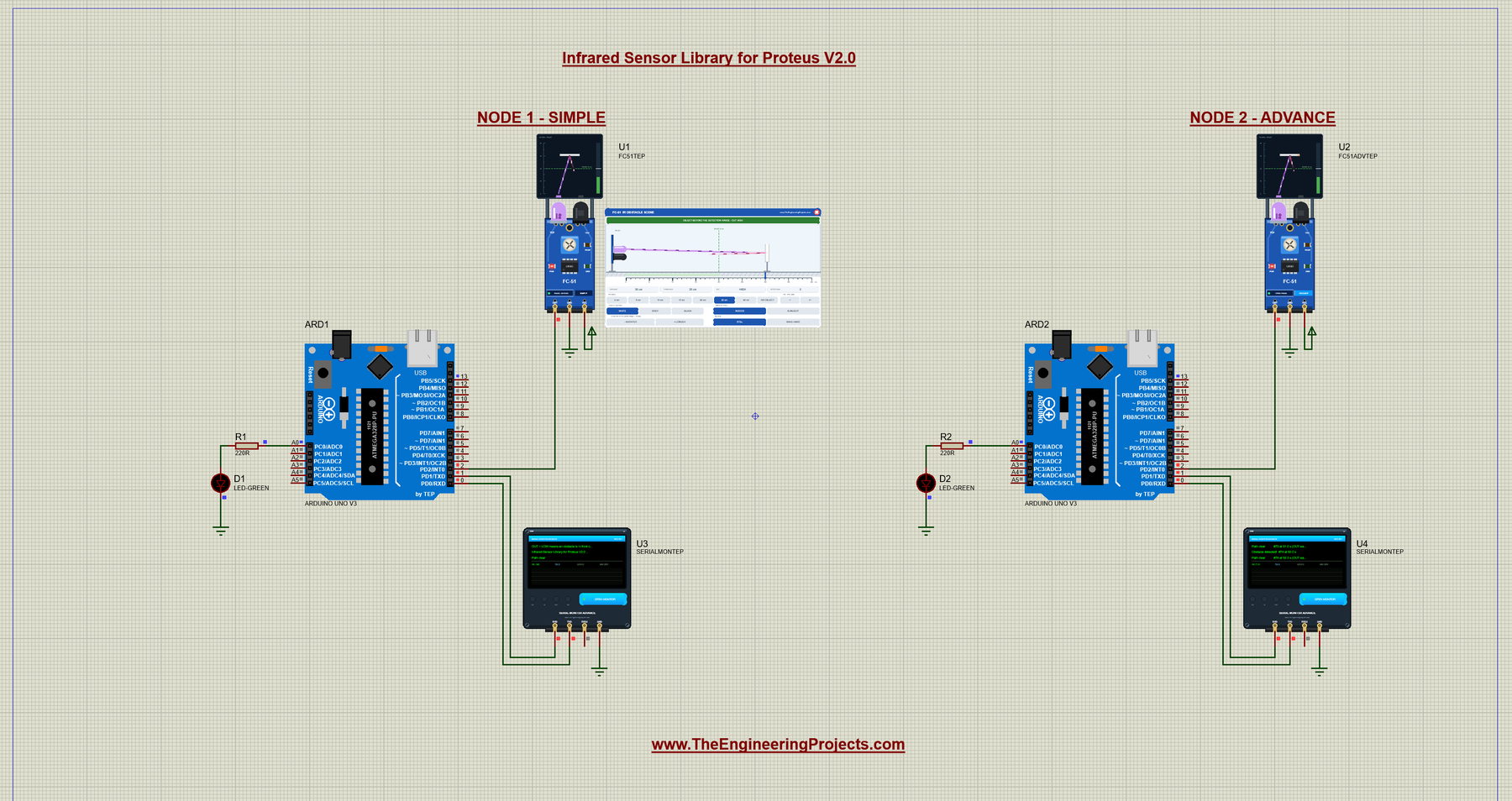
Open FC51-Obstacle-ArduinoUnoV3.pdsprj from the Proteus Simulation folder, with FC51_Obstacle.hex and both DLLs beside it. Its two Arduino UNOs from our Arduino Library for Proteus V3.0 run the same HEX file:
- NODE 1 - SIMPLE: UNO 1 (ARD1) with the FC-51 Simple (U1) and Serial Monitor U3.
- NODE 2 - ADVANCE: UNO 2 (ARD2) with the FC-51 Advance (U2) and Serial Monitor U4.
Wiring
| From | To | Why |
|---|---|---|
| FC-51 VCC / GND | Supply / ground terminals | Power (the PWR LED lights) |
| FC-51 OUT | Arduino D2 | LOW = obstacle, HIGH = clear |
| Serial Monitor RXD / TXD / GND | Arduino D1 / D0 / ground | Shows what the Arduino prints, sends what you type |
| Serial Monitor RXD2 | Not connected | OUT is one logic line; the sketch prints what it sees |
| LED + 220 Ω on A0 | Ground | From the demo template; the sketch does not use it |
D2 is a normal digital pin (see our Introduction to Arduino UNO), and pinMode(INPUT) is enough, because the module pulls OUT up itself. The sketch also switches the UNO's built-in LED on D13 with the sensor.
The Arduino Code
The sketch needs no library. It starts with the two pins:
const int SENSOR_PIN = 2;      // FC-51 OUT
const int LED_PIN = 13;        // the UNO's built-in LED
In setup(), it sets the pins, opens the serial port at 9600 baud and prints three start lines:
void setup() {
  pinMode(SENSOR_PIN, INPUT);  // INPUT is enough: the module pulls OUT up itself
  pinMode(LED_PIN, OUTPUT);
  Serial.begin(9600);
  Serial.println("FC-51 IR Obstacle Sensor demo - The Engineering Projects");
  Serial.println("OUT = LOW means an obstacle is in front of the sensor.");
  Serial.println("Infrared Sensor Library for Proteus V2.0 - type HELP for the commands.");
}
The loop reads OUT, handles the commands and then the debounce. With DEBOUNCE 0 (the start value), a change counts at once; otherwise the new reading becomes a candidate and counts only after it has lasted debounceMs:
  int reading = digitalRead(SENSOR_PIN);         // read the sensor
  unsigned long now = millis();
  readCommands();

  // DEBOUNCE: a changed reading counts once it has lasted debounceMs (0: at once)
  int state = lastState;
  if (reading == lastState) {
    candidate = -1;
  } else if (debounceMs == 0 || lastState == -1) {
    state = reading;
  } else if (reading != candidate) {
    candidate = reading;
    candidateSince = now;
  } else if (now - candidateSince >= debounceMs) {
    state = reading;
  }
When the accepted state turns LOW, the sketch lights the LED, counts the obstacle, remembers when OUT went LOW and prints the number and the time:
  if (state != lastState) {                      // something changed: report it once
    if (state == LOW) {
      digitalWrite(LED_PIN, HIGH);               // obstacle: LED on
      detections++;
      lowSince = now;
      Serial.print("Obstacle detected!  #");
      Serial.print(detections);
      Serial.print(" at ");
      printSeconds(now);
      Serial.println();
When it turns HIGH again, the sketch measures how long OUT was LOW and keeps the shortest and longest time for STATUS. The very first reading after the start just prints "Path clear":
    } else {
      digitalWrite(LED_PIN, LOW);                // clear: LED off
      if (lastState == LOW) {                    // the obstacle has gone: how long OUT was LOW
        lastLow = now - lowSince;
        if (shortestLow == 0 || lastLow < shortestLow) shortestLow = lastLow;
        if (lastLow > longestLow) longestLow = lastLow;
        Serial.print("Path clear          #");
        Serial.print(detections);
        Serial.print(" at ");
        printSeconds(now);
        Serial.print(" (OUT was LOW for ");
        printSeconds(lastLow);
        Serial.println(")");
      } else {
        Serial.println("Path clear");            // the first reading after the start
      }
    }
Times are printed in seconds with one decimal. Adding 50 ms first rounds them to the nearest 0.1 s, the same way the Advance window rounds its "OUT LOW for" value, so the two always agree:
// prints a time in milliseconds as seconds with one decimal, e.g. 12.4 s (rounded to 0.1 s)
void printSeconds(unsigned long ms) {
  ms += 50;
  Serial.print(ms / 1000);
  Serial.print('.');
  Serial.print((ms % 1000) / 100);
  Serial.print(" s");
}
At the end of the loop, WATCH prints the status line, but only when you asked for it, and the loop waits 20 ms. So the sketch reads OUT about 50 times a second and prints nothing while nothing happens:
  if (watchSeconds > 0 && now - lastStatus >= watchSeconds * 1000UL) {   // WATCH: only when asked for
    lastStatus = now;
    printStatusLine(lastState);
  }

  delay(20);                                     // read about 50 times per second
The status line shows OUT and the number of detections:
void printStatusLine(int state) {             // the status line of the earlier versions
  Serial.print("Status: OUT = ");
  Serial.print(state == LOW ? "LOW  (obstacle)" : "HIGH (clear)   ");
  Serial.print("  detections: ");
  Serial.println(detections);
}
HELP prints three short lines, so they fit the Serial Monitor's Simple interface:
void printHelp() {
  Serial.println("Commands: HELP, STATUS, RESET, WATCH s, DEBOUNCE ms");
  Serial.println("  WATCH s: a status line every s seconds (0 = off, 0-60)");
  Serial.println("  DEBOUNCE ms: a change must last ms to count (0-1000)");
}
And DEBOUNCE takes a number from 0 to 1000 ms and confirms it:
  } else if (strncmp(text, "DEBOUNCE", 8) == 0 && numberAfter(text) >= 0 && numberAfter(text) <= 1000) {
    debounceMs = numberAfter(text);
    if (debounceMs == 0) Serial.println("Debounce off: every change counts.");
    else {
      Serial.print("Debounce: a change must last ");
      Serial.print(debounceMs);
      Serial.println(" ms.");
    }
The commands live in RAM, so a new Run starts with WATCH and DEBOUNCE off. To change the sketch, export a new HEX file and load it into both UNOs; see How to get the HEX file from Arduino. New to Arduino? Start with our Arduino Tutorial for Beginners.
Serial Monitor Commands
| Command | What it does | Answer |
|---|---|---|
| HELP | The command list | Three lines, starting "Commands: HELP, STATUS, RESET, WATCH s, DEBOUNCE ms" |
| STATUS | OUT, the detections and the LOW times | Two lines: the status line, then the last, shortest and longest LOW time with the WATCH and DEBOUNCE settings |
| RESET | The detection counter back to 0 | "Counter reset: 0 detections." |
| WATCH s | A status line every s seconds (0 = off, 0 to 60) | "Watch: a status line every 2 s." / "Watch off." |
| DEBOUNCE ms | A change must last ms before it counts (0 to 1000) | "Debounce: a change must last 50 ms." / "Debounce off: every change counts." |
An unknown word gets "Unknown command: FOO - type HELP" (with your word instead of FOO).
How to Run the Demo
- Press Run. Both Serial Monitors (9600 baud) and U2's pop-up open. U3 and U4 print the three start lines and "Path clear"; the PWR LEDs light and the IR LEDs pulse.
- On U1's panel, click 10 cm, wait a second and click NO OBJECT. Then try GREY and BLACK at 15 cm, the pot, SUNLIGHT and WAVE HAND.
- Use the quick buttons: STATUS, WATCH 2 and WATCH 0 on U3; STATUS, DEBOUNCE 50, RESET and HELP on U4.
- On U2, watch the Scene page with its event log, then run the four tools on the Test tab.
- Close U2's window and open it again with OPEN PANEL; close U1's panel with its red X and open it with PANEL.
Infrared Sensor Proteus Simulation Results
The Serial Monitor in Its Simple Interface
Both monitors in this demo run in the Simple interface of our TEP Serial Monitor, as in every monitor screenshot here. Only the log, the send box and one slim toolbar row stay visible (baud rate, follow, pause, search and clear), so the window stays small.
- Switch to it: right-click the log and choose Simple interface, or press Ctrl+Shift+U.
- Back to the full view: click the corner button (the expand arrows at the top right), press Esc or Ctrl+Shift+U, or right-click and choose Full interface.
- Your choice is remembered.
Type commands such as STATUS or WATCH 2 in the send box and press Enter; the quick buttons come back with the full view. The demo's lines stay under 80 characters, so they fit this small window. Read all about the monitor in TEP Serial Monitor Advance for Proteus.
Start-Up
After Run, U3 prints the three start lines and then the first reading. The object starts at 30 cm, beyond the range, so the first reading is "Path clear":
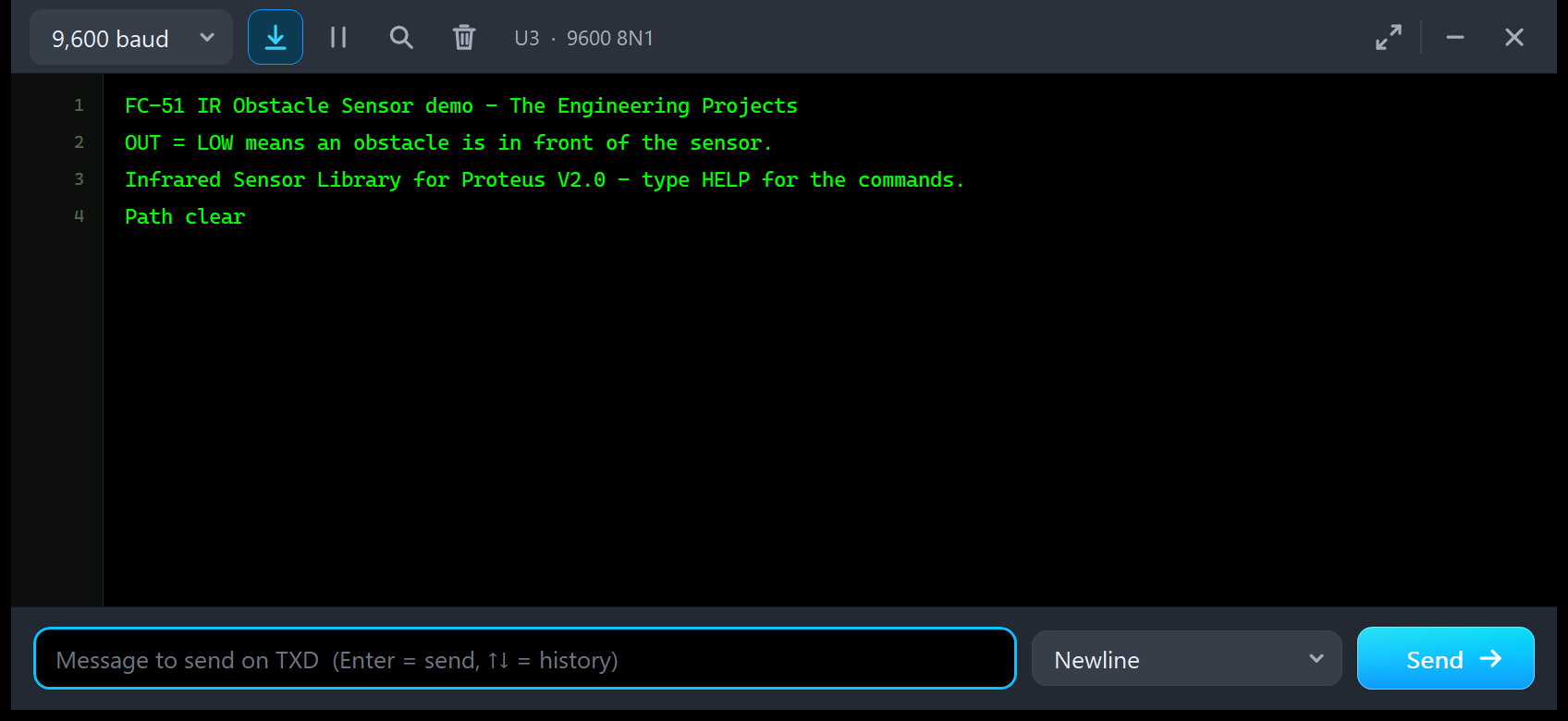
FC-51 IR Obstacle Sensor demo - The Engineering Projects
OUT = LOW means an obstacle is in front of the sensor.
Infrared Sensor Library for Proteus V2.0 - type HELP for the commands.
Path clear
After that, the monitor stays quiet until OUT changes.
Obstacles and WAVE HAND
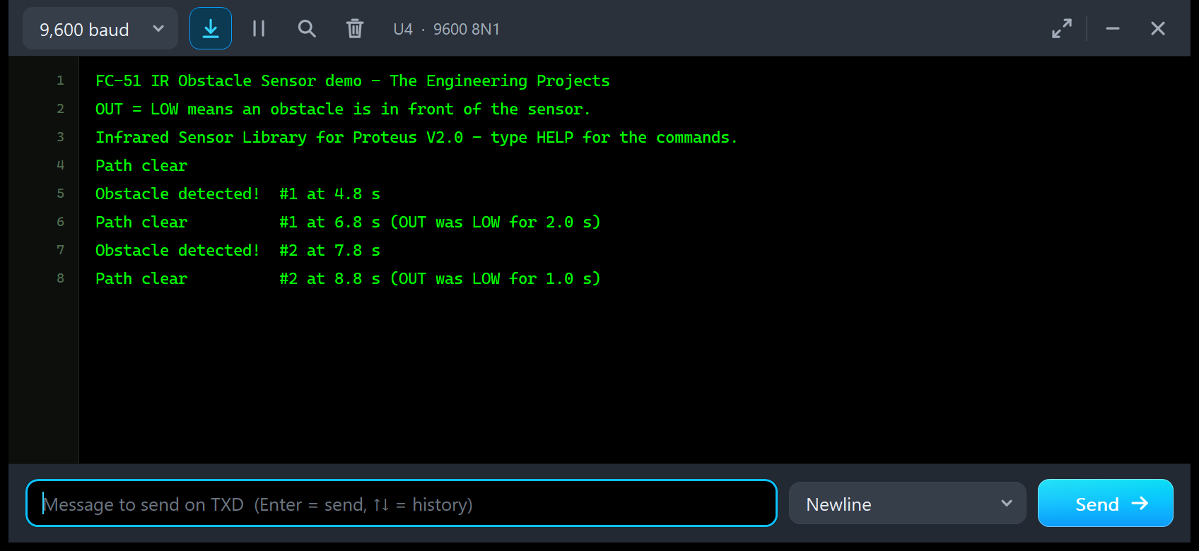
FC-51 IR Obstacle Sensor demo - The Engineering Projects
OUT = LOW means an obstacle is in front of the sensor.
Infrared Sensor Library for Proteus V2.0 - type HELP for the commands.
Path clear
Obstacle detected!  #1 at 4.8 s
Path clear          #1 at 6.8 s (OUT was LOW for 2.0 s)
Obstacle detected!  #2 at 7.8 s
Path clear          #2 at 8.8 s (OUT was LOW for 1.0 s)
This is U4, the monitor of the Advance node, in the same run as the Scene page above. I clicked 10 cm on U2: OUT went LOW, and the sketch printed obstacle #1 at 4.8 s. A moment later I clicked WAVE HAND. The hand begins by holding the object in the beam for 1 s, so the first LOW lasted the time the object already stood at 10 cm plus that first second: 2.0 s. From then on, the hand works in a steady rhythm, 1 s in and 1 s out, and every LOW lasts 1.0 s.
Compare the times with the event log: the sketch printed 6.8 s, 7.8 s and 8.8 s, and the model logged its OUT edges at 6.848, 7.848 and 8.848 s. The sketch reads OUT about every 20 ms and rounds to 0.1 s, so the printed times are the model's edges. The model writes the same LOW time to the Simulation Log, for example "NO OBSTACLE - OUT HIGH (OUT was LOW for 1.0 s)".
Let WAVE HAND run, and the pairs keep coming every 2 s, as in the featured image, where U4 has reached #95 at 175.0 s. The sketch keeps its own counter, which RESET sets back to 0, so its numbers need not match the model's count in the pop-up (98 there).
STATUS, WATCH and DEBOUNCE
Click STATUS on U3 after one obstacle of one second, and you get two lines like this example from the README:
Status: OUT = HIGH (clear)     detections: 1
  LOW: last 1.0 s, shortest 1.0 s, longest 1.0 s; watch 0 s; debounce 0 ms
WATCH 2 answers "Watch: a status line every 2 s." and then prints the first of those lines every 2 s; WATCH 0 answers "Watch off.". On U4, DEBOUNCE 50 answers "Debounce: a change must last 50 ms.". Now run the Response time tool: with DEBOUNCE 50, the sketch counts the three held steps of 200 ms but ignores the short passes of 1 to 5 ms. That is exactly the software fix for a real FC-51 that chatters near its threshold.
Troubleshooting
- A grey or black object is not detected at 15 cm: correct. Dark objects reflect less infrared (grey 0.55 x, black 0.2 x the pot's range). Move the object closer or turn the pot up.
- OUT is LOW with nothing in front: SUNLIGHT with the pot above 15 cm; the sun's infrared alone crosses the threshold. Turn the pot down to 14 cm or less.
- The sketch counts more obstacles than expected near the threshold: type DEBOUNCE 50 (a real module chatters there).
- The Test tab says "Cannot start: ...": the reason is in the message: no power, another test is running, the sun's false trigger, or a range under 1 cm.
- The part is not simulated or there is no panel: TEPFC51.DLL is missing from MODELS and from the project folder. No monitor window: TEPSERIALMON.DLL is missing, or click OPEN MONITOR on the monitor part.
- The Advance pop-up does not appear: click OPEN PANEL on the board, or turn "Open the panel at Run" back on in Settings.
- The red X does not close the Simple panel: the design holds an older symbol. Replace TEPFC51.LIB, delete TEPFC51.IDX and pick the part again.
- Your own sketch uses SoftwareSerial to receive: Proteus 8.5 cannot receive with SoftwareSerial; use the hardware Serial, as the demo does, or AltSoftSerial.
Things to Know Before Using a Real FC-51 Module
The demo sketch uses no library, so it runs on a real UNO and FC-51 as it is. Keep in mind:
- Supply: 3.3 to 5 V, about 20 mA, so the FC-51 works with 5 V and 3.3 V boards. OUT swings to the supply voltage through its pull-up, so at 5 V it suits a 5 V UNO; on a 3.3 V board, power the module from 3.3 V too.
- The pot: clockwise = longer, about 2 to 30 cm for a white object. Ordinary objects are seen at 15 to 20 cm in practice.
- Dark objects: much shorter range; matte black may not trigger at all. Test with your real objects.
- Sunlight and lamps: direct sunlight, strong infrared sources and some LED lamps cause false detections. Turn the pot down or shade the sensor.
- Chatter: the real LM393 board has no hysteresis, so OUT can chatter right at a long threshold. Debounce in software (the sketch's DEBOUNCE) or keep away from the threshold.
- Angle: the sensor sees in a cone of about 35°. An object at the side may be detected where our model, which keeps it on the axis, would not.
- Pin order: OUT GND VCC is the usual order, but check the silkscreen of your board.
Limitations of the Simulation
- Not modelled: the analog photodiode signal and the IR LED current, the 35° detection angle (the object is always on the axis), the object's size and angle, real reflectivities (the grey and black factors are estimates), the effect of the supply voltage on the range, and the chatter of the comparator (the model has a hysteresis instead).
- The model is our own implementation, written from the published FC-51 and LM393 descriptions; it contains no third-party code, and it needs no Visual C++ redistributable.
- Licences: the demo sketch uses no Arduino library. The HEX file is built with the Arduino AVR core 1.8.6, which includes LGPL-licensed code; its source code is on GitHub.
- Tested in Proteus 8.5 in October 2026 (the demo, both panels, the four tools, Settings, Help and every screenshot here) and with 1,924 automatic PC checks, all passed: 147 on the model, 395 on the complete Proteus model, 27 with the real demo sketch on two UNOs and 1,355 on the rendered pop-up and boards. Proteus 7 is not supported.
Want the distance in centimetres instead of a yes or no? See our Ultrasonic Sensor Library for Proteus V2.0 or our VL53L0X Sensor Library for Proteus. To detect people by their body heat, take our PIR Sensor Library for Proteus V4.0. All our motion and distance sensors are listed in Motion and Distance Sensor Libraries for Proteus.
So, that was all about the Infrared Sensor Library for Proteus V2.0. I hope the IR VIEW screen, the scene with its colours, sunlight and waving hand, the event log and the four test tools make the FC-51 much easier to understand, so your obstacle detector works the first time you wire a real module. If you use the Infrared Sensor Library for Proteus in a project, please share your feedback in the comments or in our forum, and if you have any questions, ask in the comments and I will help you out. Till the next tutorial, take care and have fun!