Hello friends, I hope you all are doing great. Today, I am going to share the Adafruit QT Py ESP32-S3 Library for Proteus. The QT Py is Adafruit's thumb-sized board: 20.6 x 17.8 mm, 14 pins, and on it an ESP32-S3 with Wi-Fi, a NeoPixel and a STEMMA QT socket. It may be the smallest way to put a powerful Wi-Fi chip into a project. With this library it runs your ESP32-S3 Arduino sketch in Proteus 8.5 and joins our virtual Wi-Fi network.
Adafruit QT Py ESP32-S3 Library for Proteus
Latest version: V1.0 (November 2026, this tutorial)
Other ESP32 boards and modules: ESP32 DevKit V1 · ESP32-DevKitC V4 · ESP32-S3 DevKitC-1 · ESP32-C3 SuperMini · ESP32-C6 DevKitC-1 · TTGO T-Display · T-Display S3 · XIAO ESP32-C3 · XIAO ESP32-S3 · ESP32 Feather V2 · ESP32-C5 DevKitC-1 · Olimex ESP32-POE · FireBeetle 2 ESP32-E · T-Call SIM800L · T-SIM7600 · T-Beam Supreme · M5StickC PLUS2 · ESP32-2432S028 CYD · M5Stack AtomS3 · M5Stack Core2 · LilyGO T-Deck · LOLIN S2 Mini · Heltec WiFi LoRa 32 V3 · LilyGO T-Beam · ESP32-CAM · ESP32-WROOM-32 · AirLift WiFi Shield · AirLift ESP32 Breakout · WT32-ETH01
Modules: Micro SD · MAX485 RS485 · MCP2515 CAN · DS3231 RTC · DFPlayer Mini
Helping Tools
- Laptop WiFi Monitor: a laptop on the Wi-Fi of your design: a browser, a TCP / UDP terminal and ping
- Mobile WiFi Monitor: a smartphone that opens the pages of your board and sends it commands
- Serial Monitor Advance: a serial terminal window for the UART of your board
For the demo we built a Wi-Fi alarm clock that never has to be set by hand. At the start the board asks an internet time server for the time and stores it in a DS3231 clock chip, a TM1637 display shows the hours and minutes, the NeoPixel flashes when the alarm rings, and a phone and a laptop control it all from the board's web page.
NOTICE: Proteus has no ESP32-S3 model, so our team has put a lot of effort into building this board ourselves: the QT Py's pins, NeoPixel, buttons and Wi-Fi are all our own model, and your sketch compiles with our free TEP Boards for Proteus add-on. Your feedback is the fuel that keeps us going, so please tell us what you think in the comments below or in the Adafruit QT Py ESP32-S3 board of our forum. And if our free libraries help you, you can buy us a coffee. So, let's get started with the Adafruit QT Py ESP32-S3 Library for Proteus:
What is the Adafruit QT Py ESP32-S3?
QT Py is Adafruit's family of tiny boards, all with the same 14 pins and the same footprint, each with a different chip. The QT Py ESP32-S3 carries Espressif's ESP32-S3: two Xtensa LX7 cores at 240 MHz with vector instructions, Wi-Fi 4 and Bluetooth 5 LE, with native USB on the USB-C port. Beside the chip are the antenna, a NeoPixel, the RST and BOOT buttons and a STEMMA QT socket, so sensors can plug in with one cable and no soldering. The pins fit a breadboard and carry an I2C bus, an SPI bus, a UART and four analog inputs.
| QT Py ESP32-S3 | Standard ESP32-S3 DevKitC-1 | |
|---|---|---|
| Size | 20.6 x 17.8 mm | 69 x 25 mm |
| Pins | 2 x 7 (11 GPIOs) | 2 x 22 |
| Extras | NeoPixel, STEMMA QT socket | RGB LED |
| USB | USB-C, the chip's own USB | two USB-C ports |
| Good for | small finished gadgets | the lab bench |
Why the QT Py ESP32-S3?
Pick a QT Py when the finished gadget has to be small and neat. A desk clock, a badge, a status light or a smart button does not need 40 pins, and a board that fits behind a display leaves room for everything else. The STEMMA QT socket means a sensor needs no soldering at all, and because the pin layout is shared with Seeed's XIAO family, many small carrier boards fit it too.
Features of the QT Py ESP32-S3 Library for Proteus
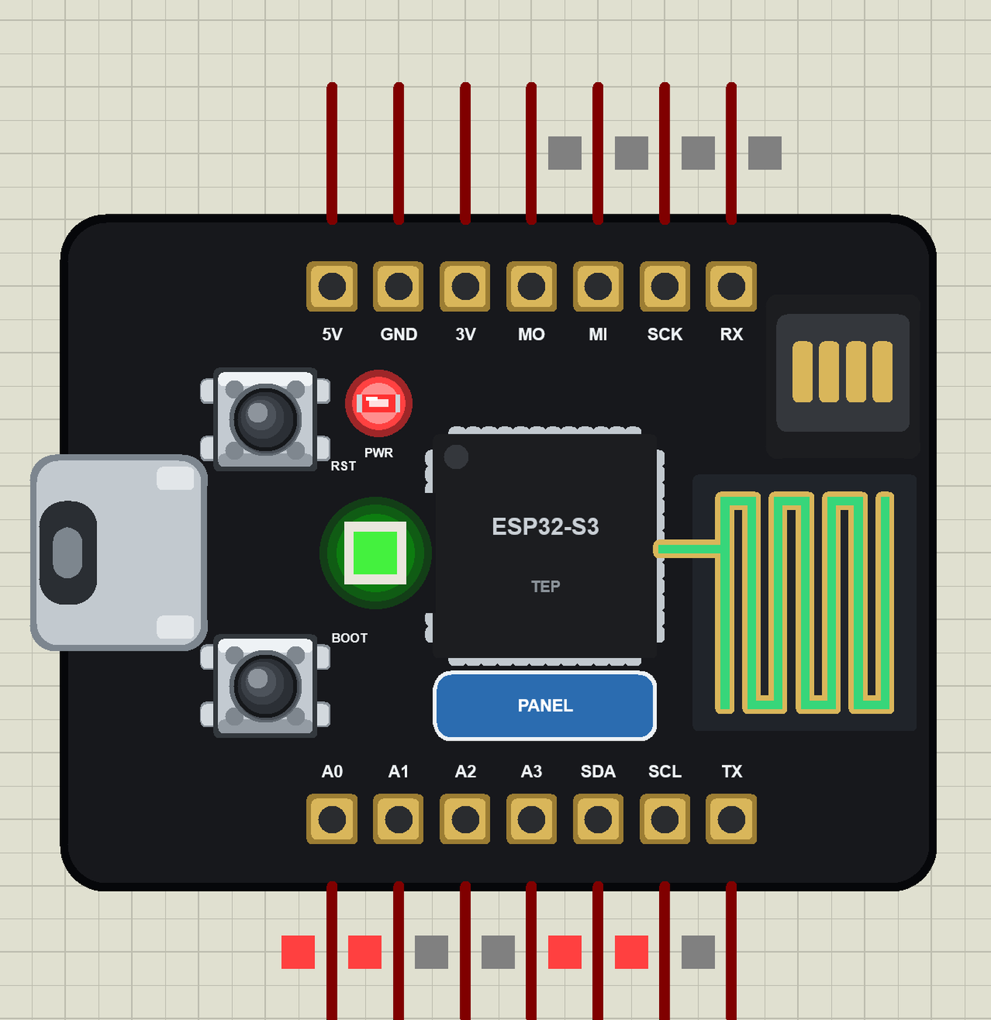
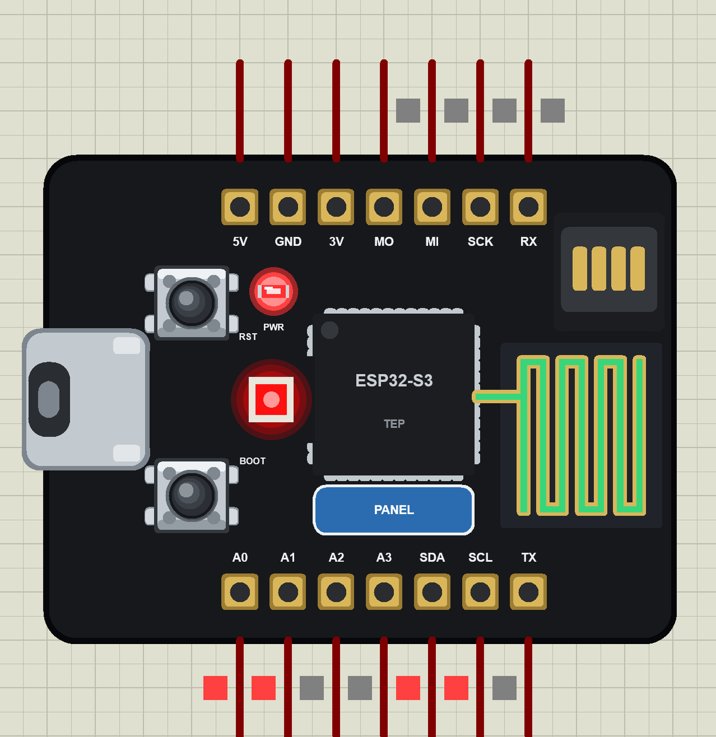
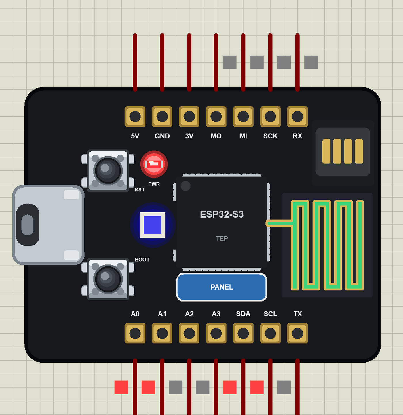
- The board as it looks: the black QT Py with USB-C, RST and BOOT, the NeoPixel, the ESP32-S3 chip, the PCB antenna and the STEMMA QT socket, drawn at its real proportions.
- Your sketch: a .hex for "QT Py ESP32-S3 (TEP Proteus)" with the QT Py's names - A0 to A3, SDA, SCL, TX, RX, SCK, MI, MO - analogRead 0 to 4095, analogWrite and ledc PWM, attachInterrupt, Serial, Serial1, Wire and SPI.
- Wi-Fi and time: WiFi.begin, WebServer, HTTPClient, mDNS, and configTime with our virtual NTP server; the board is 192.168.1.101 in the demo.
- The NeoPixel and buttons work: rgbLedWrite colours the NeoPixel on the part, BOOT pulls GPIO0 LOW and RST resets the board.
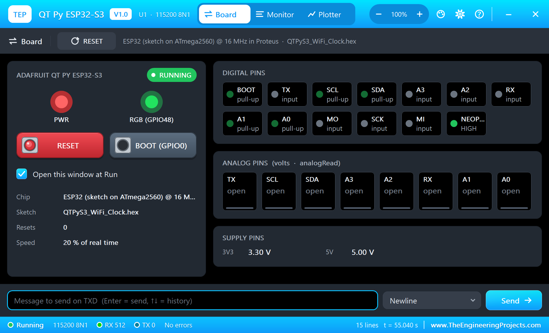
- The panel and the serial monitor: the board's panel (Wi-Fi, Pins, Test) and the built-in serial monitor with Monitor, Plotter and Board tabs - our TEP header, no Windows title bar.
- A complete package: about 3.7 MB with the board, the add-on, the DS3231, TM1637 and monitor libraries and the demo, without the source code of the models.
The QT Py ESP32-S3 in Proteus
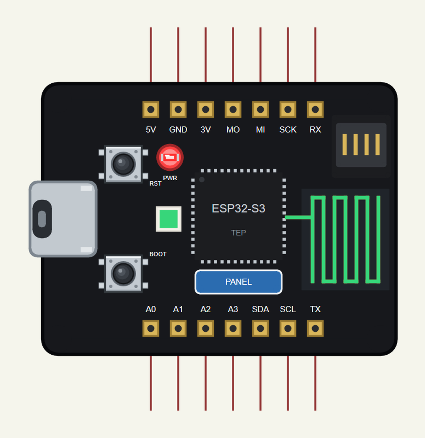
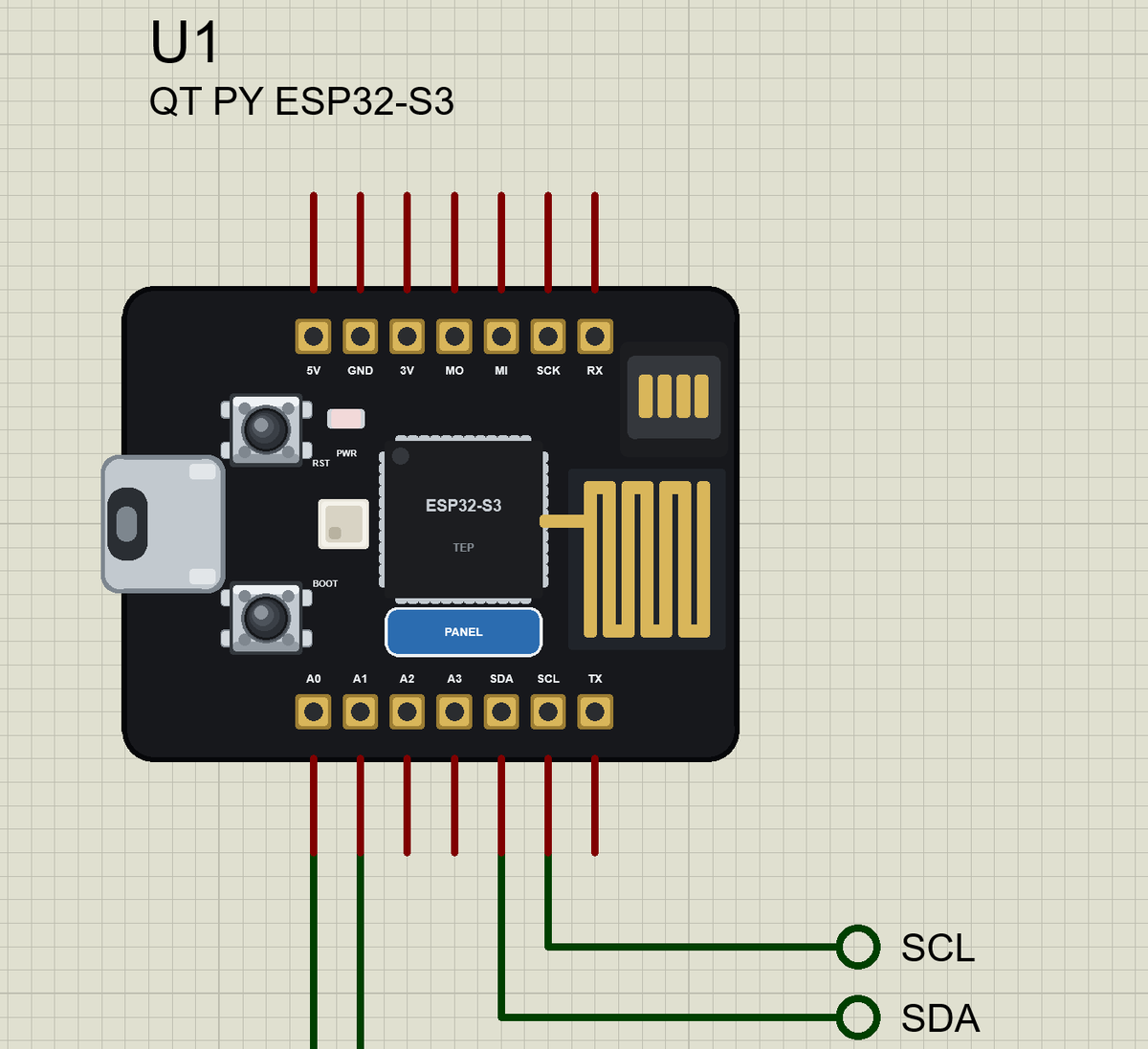
Search QT PY in Pick Devices; the device QT PY ESP32-S3 is in TEPQTPYS3.LIB (Microprocessor ICs, ESP32 Boards), with the prefix U. The board lies with the USB-C port on the left. Click the USB-C port to open the serial monitor and the PANEL pad (or the chip) to open the board's panel. One QT Py ESP32-S3 can be placed in a design.
The Pins
| Pins | GPIO | What the library does with them |
|---|---|---|
| A0 to A3 | 18, 17, 9, 8 | analogRead, GPIO, PWM, interrupt |
| SDA / SCL | 7 / 6 | Wire |
| TX / RX | 5 / 16 | Serial1 |
| SCK / MI / MO | 36 / 37 / 35 | SPI |
| 3V, 5V, GND | - | 3.3 V, 5 V, ground |
| On the board | 0, 39 and 38 | the BOOT button, the NeoPixel and its power switch |
As on the real board, Serial is the USB port, which in Proteus means the built-in serial monitor, and TX and RX stay free for a GPS or a GSM module.
Download Adafruit QT Py ESP32-S3 Library for Proteus
Click the button below to download Adafruit-QT-Py-ESP32-S3-Library-for-Proteus-v1.0.zip (about 3.7 MB, without the source code of the models):
Adafruit QT Py ESP32-S3 Library for Proteus V1.0- README.txt: installation, the demo, the pins, the properties, troubleshooting and the limits.
- Proteus Library Files:
TEPQTPYS3.LIBand the demo's parts:TEPDS3231.LIB,TEPTM1637.LIB,TEPLAPTOP.LIBandTEPMOBILE.LIB. - Proteus Model Files:
TEPNET.DLL(the board, the laptop, the phone and the network),TEPDS3231.DLLandTEPTM1637.DLL. - Arduino Code: the demo sketch and the TEP Boards for Proteus add-on 1.42.0.
- Proteus Simulation: the demo project, its HEX file and copies of the DLLs.
No Proteus yet? Read How to Download and Install Proteus 7 and 8. New to libraries? Follow How to Install a New Library in Proteus.
How to Install Adafruit QT Py ESP32-S3 Library for Proteus
- Close Proteus and extract the whole zip file, for example to your Desktop.
- Copy the files from Proteus Library Files into the LIBRARY folder of Proteus.
- Copy the DLLs from Proteus Model Files into the MODELS folder, replacing an older TEPNET.DLL.
- Delete
TEPQTPYS3.IDXfrom the LIBRARY folder if it is there. - For your own sketches, copy Arduino Code\TEP Boards for Proteus\hardware into your Arduino sketchbook (Documents\Arduino) and restart the Arduino IDE; the board is QT Py ESP32-S3 (TEP Proteus). Install RTClib and TM1637 by Avishay Orpaz from the Library Manager.
- Start Proteus, press P and search for QT PY.
Demo: a Wi-Fi Alarm Clock
Every clock has the same small annoyance: someone has to set it, and set it again after a power cut. A clock with Wi-Fi can ask the internet instead. But if it depends on the network, it stops being a clock when the router goes down. The neat answer uses both: Wi-Fi to get the right time once, and a battery-backed clock chip to keep it from then on. That is a real pattern in products, and it fits on a QT Py with two tiny modules.
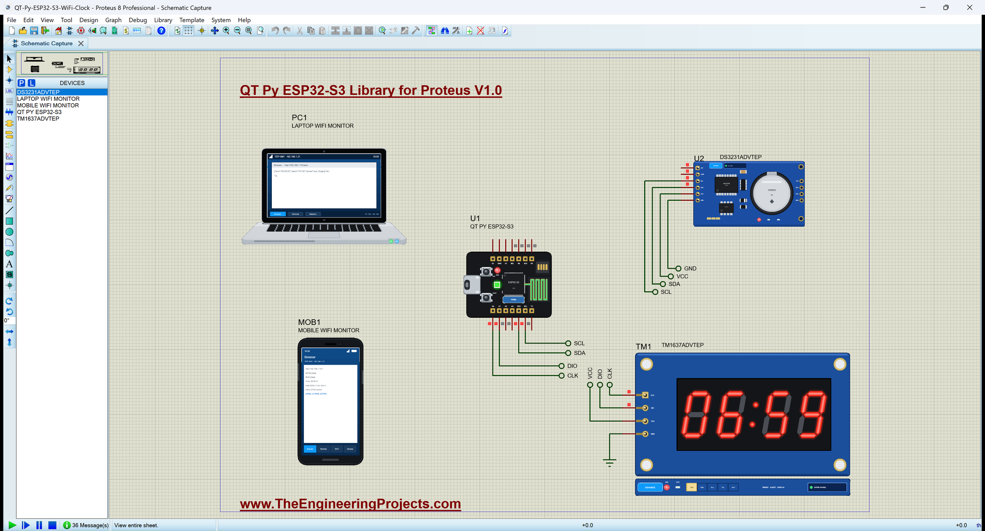
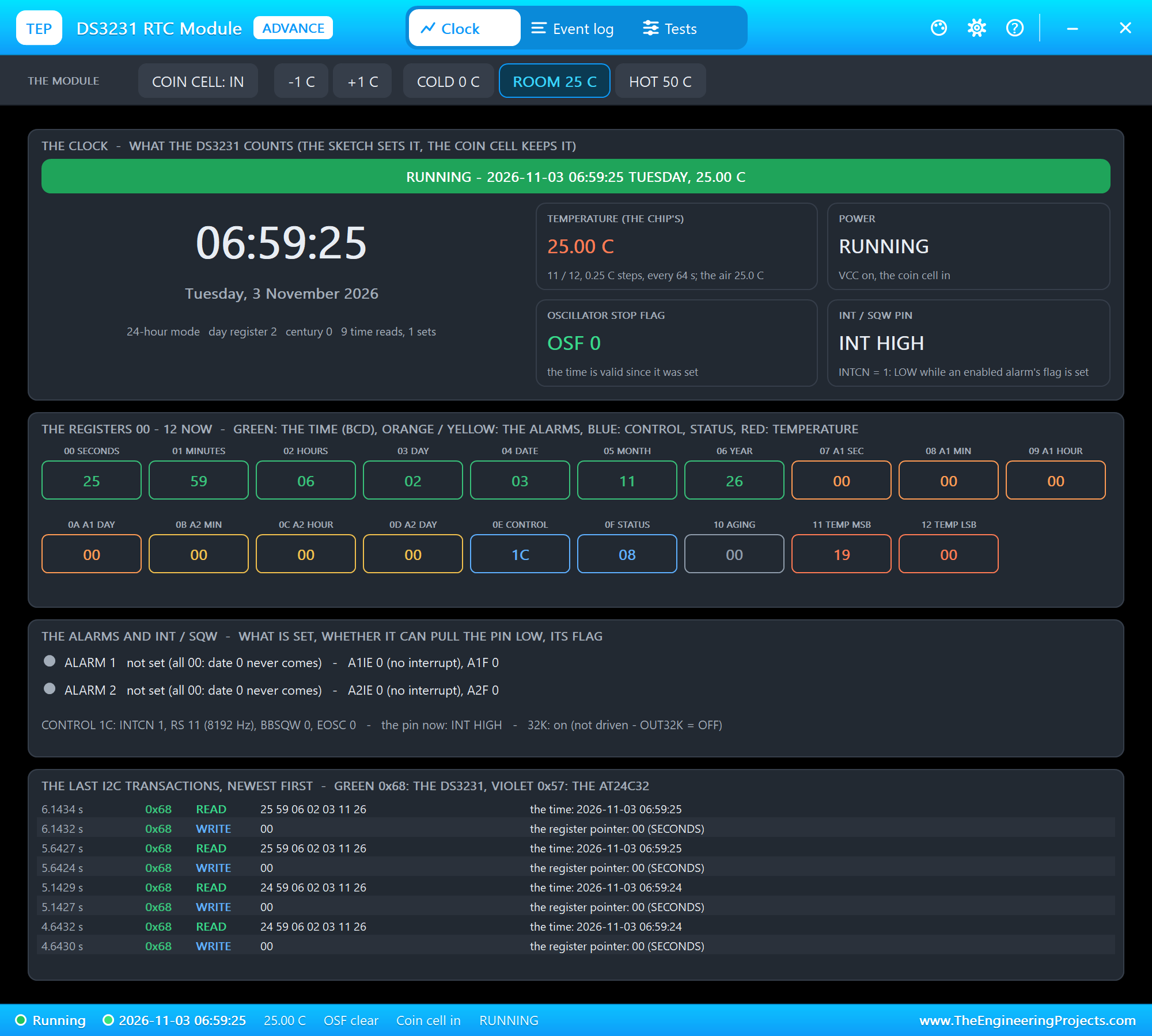
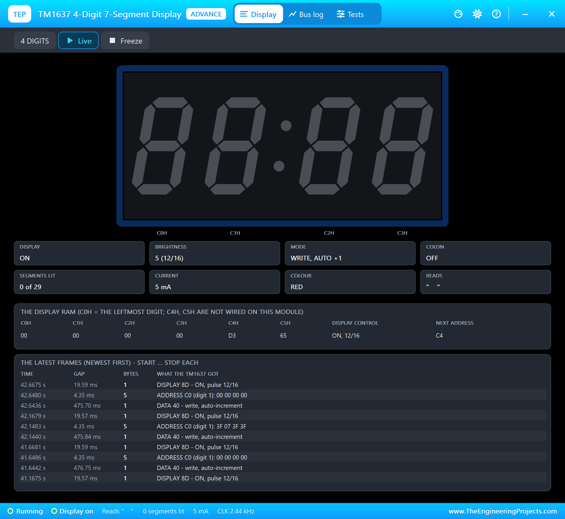
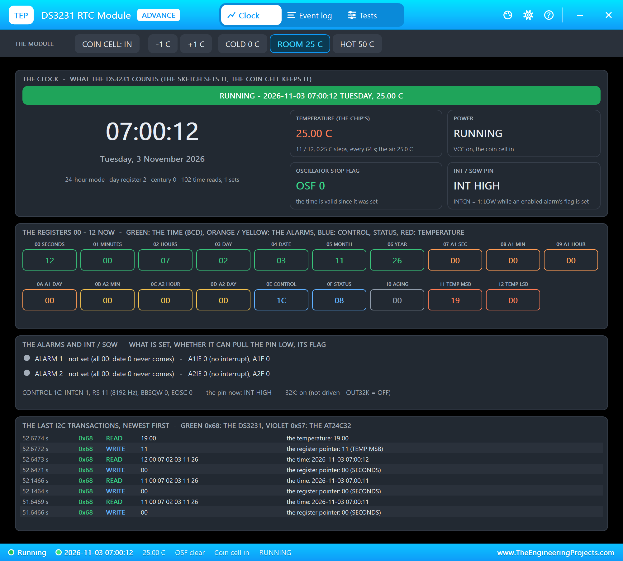
Open QT-Py-ESP32-S3-WiFi-Clock.pdsprj. U1 runs QTPyS3_WiFi_Clock.hex. U2 is the DS3231 from our DS3231 RTC Module Library for Proteus and TM1 the 4-digit display from our TM1637 7-Segment Display Library for Proteus - both in the Advance version, so they open their pop-up windows at Run. PC1 is the Laptop WiFi Monitor and MOB1 the Mobile WiFi Monitor.
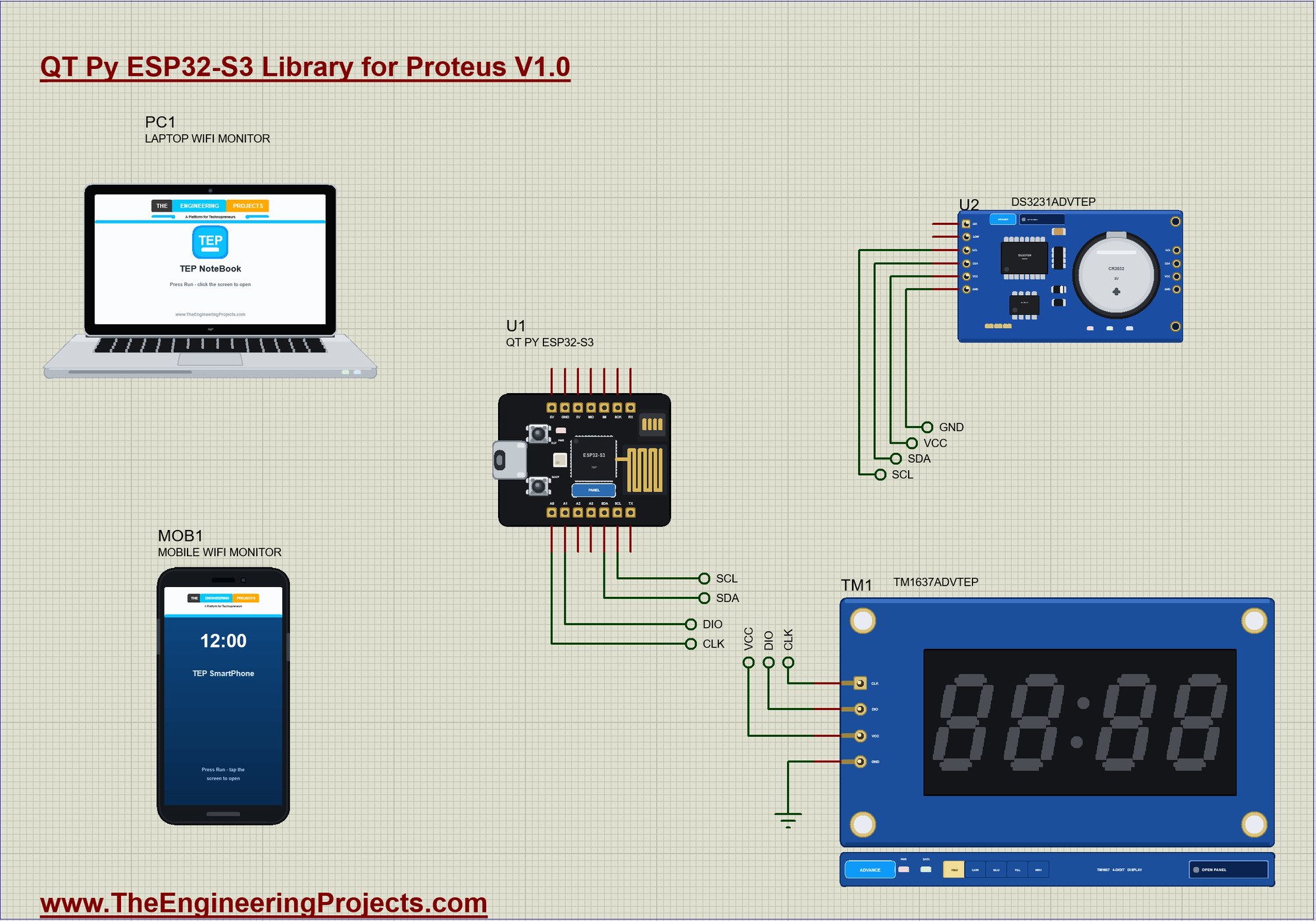
| Module pin | Net label | QT Py pin | What it does |
|---|---|---|---|
| DS3231 SDA, SCL | SDA, SCL | SDA, SCL | I2C, the address 0x68 |
| DS3231 VCC, GND | VCC, GND | 3V, GND | the supply |
| TM1637 CLK | CLK | A0 | the display's clock |
| TM1637 DIO | DIO | A1 | the display's data |
| TM1637 VCC, GND | VCC, GND | 3V, GND | the supply |
How NTP Works
NTP, the Network Time Protocol, is how computers agree on the time. The board sends one small UDP packet to a time server and gets back the number of seconds since 1900. It also measures how long the question took, and takes half of that off, so the answer is accurate to a few milliseconds. On an ESP32 two functions do all of this: configTime() names the server and your time zone, and getLocalTime() fills a structure with the date and time. In our simulation the virtual router answers as the time server, so the sketch is the one you would use on real hardware.
Why Keep a DS3231?
The ESP32 has its own clock, but it drifts by seconds a day, and it forgets everything when the power goes. The DS3231 is a clock chip with a temperature-compensated crystal, accurate to about a minute a year, and its coin cell keeps it running for years. So the sketch writes the NTP time into it once, then simply reads it back. The chip also has a temperature sensor, used for the compensation, which is why the page can show the room temperature with no extra part:
void syncClock() {                                          // NTP into the DS3231
  configTime(UTC_OFFSET_S, 0, "pool.ntp.org");
  struct tm t;
  if (!getLocalTime(&t)) { Serial.println(F("No NTP answer - the DS3231 keeps its own time")); return; }
  rtc.adjust(DateTime(t.tm_year + 1900, t.tm_mon + 1, t.tm_mday, t.tm_hour, t.tm_min, t.tm_sec));
  Serial.print(F("NTP time written to the DS3231: ")); Serial.println(rtc.now().timestamp(DateTime::TIMESTAMP_TIME));
}
The Display
The TM1637 drives four 7-segment digits and a colon over two wires. It looks like I2C but is not: it has no address, so it needs its own two pins, A0 and A1 here. showNumberDecEx prints a number, the second argument lights the colon, and the last one keeps the leading zero, so that seven in the morning reads 07:00. Blanking the display while the alarm rings makes the digits flash:
void showTime() {
  if (ringing && flash) { display.clear(); return; }
  display.showNumberDecEx(now.hour() * 100 + now.minute(), colon ? 0b01000000 : 0, true);
}
The Heartbeat of the Sketch
Everything in this clock happens in one function, which runs twice a second. It reads the time, toggles the colon and the flash, checks the alarm and repaints. Because it uses millis() and never delay(), the web server keeps answering all the time:
void tick() {                                               // twice a second
  if (millis() < nextTick) return;
  nextTick = millis() + 500;
  now = rtc.now();
  colon = !colon;
  flash = !flash;
  checkAlarm();
  showTime();
  showPixel();
}
The Alarm
The check runs only when the minute changes, so the alarm fires once and a STOP in the same minute does not start it again:
void checkAlarm() {
  static int lastMinute = -1;
  if (now.minute() == lastMinute) return;
  lastMinute = now.minute();
  if (armed && now.hour() == alarmHour && now.minute() == alarmMinute) {
    ringing = true; rings++;
    Serial.print(F(">> ALARM ")); Serial.println(now.timestamp(DateTime::TIMESTAMP_TIME));
  }
}
The NeoPixel
The QT Py's NeoPixel works as a status light: green when the alarm is armed, blue when it is off, and red flashing while it rings. The real board switches the NeoPixel's power with GPIO38, so setup() turns that on first:
void showPixel() {
  if (ringing) rgbLedWrite(RGB_BUILTIN, flash ? 120 : 0, 0, 0);
  else if (armed) rgbLedWrite(RGB_BUILTIN, 0, 60, 0);
  else rgbLedWrite(RGB_BUILTIN, 0, 0, 60);
}
The Web Page and the JSON
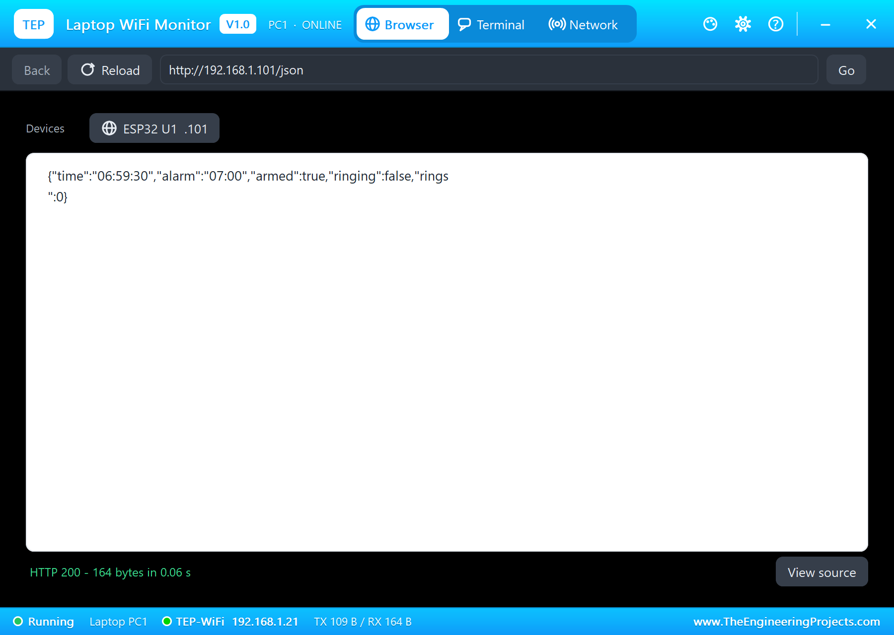
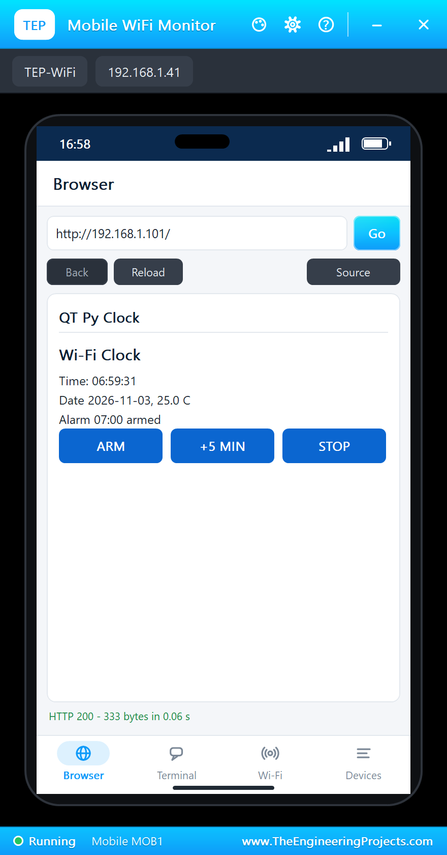
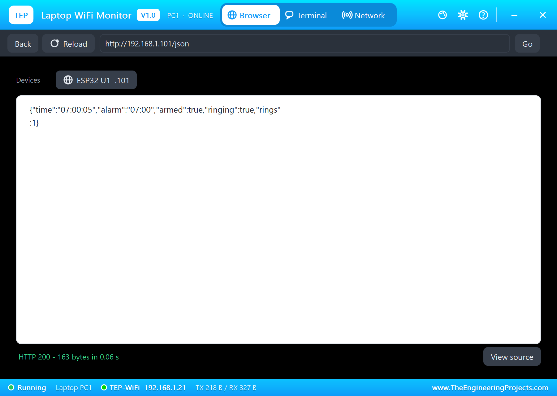
The board serves two addresses. / is a small HTML page for a person, with the time, the date, the temperature and three links that work as buttons. /json gives the same facts as one line of JSON for a program, and that is the address the laptop opens here. The split is worth copying in your own projects: a phone app, a Python script or a home automation server can read the JSON without having to pick numbers out of HTML. Each page is built fresh from the variables that tick() keeps up to date, so a request costs only a few milliseconds and the display never stutters:
void handleJson() {
  String j = "{\"time\":\"" + String(now.timestamp(DateTime::TIMESTAMP_TIME)) + "\",\"alarm\":\"" + alarmText() + "\",\"armed\":" + String(armed ? "true" : "false");
  j += ",\"ringing\":" + String(ringing ? "true" : "false") + ",\"rings\":" + String(rings) + "}";
  server.send(200, "application/json", j);
}
The three links change the state and then call handleRoot(), so every press answers with the new page straight away. That one habit keeps the sketch short: there is only one place where the page is drawn, and it can never show something different from what the alarm is really doing.
UTC and Your Time Zone
An NTP server always answers in UTC, the world's reference time, and knows nothing about where you are. The sketch has to shift it, and the first argument of configTime() is that shift in seconds. Pakistan is five hours ahead of UTC, so UTC_OFFSET_S is 18000; for London in winter it would be 0, for New York in winter -18000. The second argument is the daylight saving shift, which stays 0 here. Notice that the sketch writes the local time into the DS3231. Many projects store UTC in the chip and convert it on every read, which is the better choice for a data logger, but for a clock on a desk the simpler way is fine and it leaves the chip showing what you expect.
Run the Demo
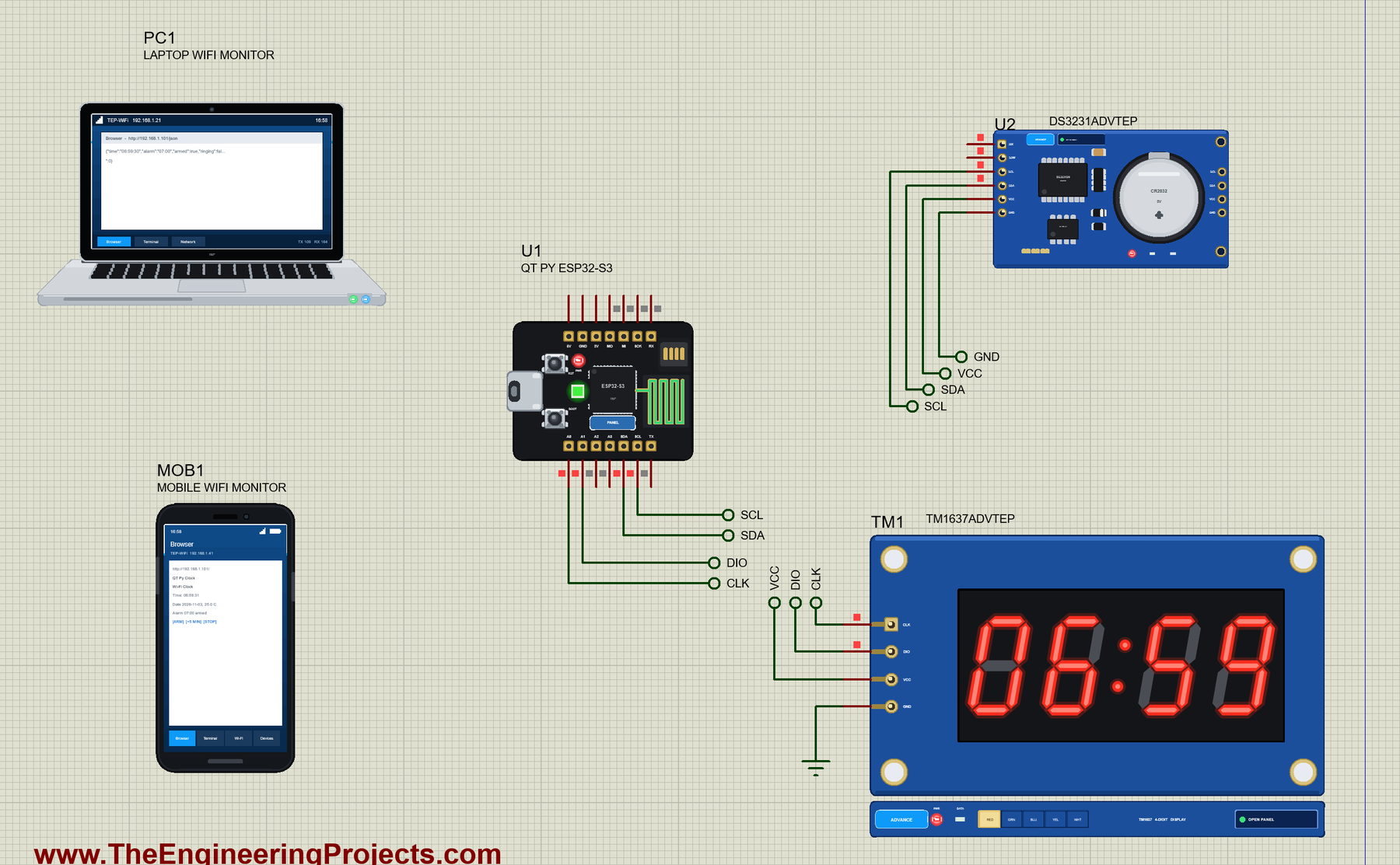
Press Run. The serial monitor opens, the DS3231 answers, the board joins TEP-WiFi and the time is written to the clock chip. The board's TIME property starts the demo at 01:59:20 UTC, which is 06:59:20 in the UTC + 5 of the sketch, so you do not have to wait long for the alarm:
QT Py ESP32-S3 Wi-Fi Clock - The Engineering Projects
DS3231 ready
Connecting to TEP-WiFi
NTP time written to the DS3231: 06:59:22
Clock page: http://192.168.1.101/
Time 06:59:22  25.0 C  alarm 07:00 armed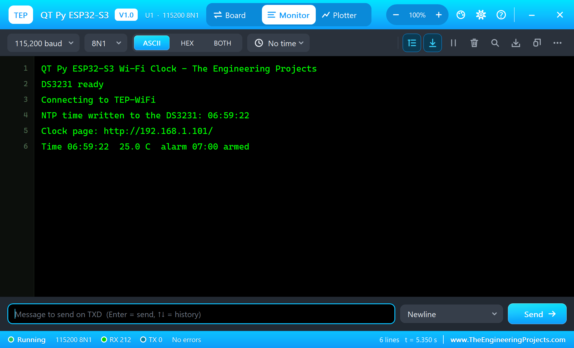
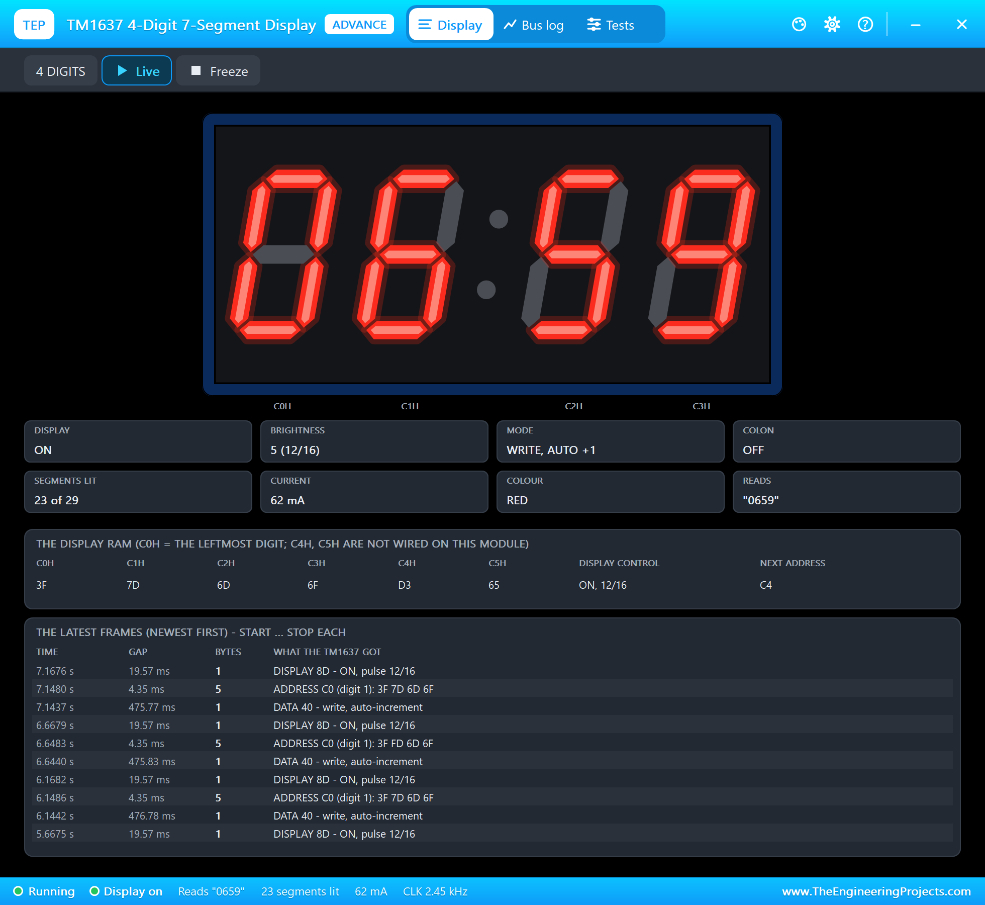
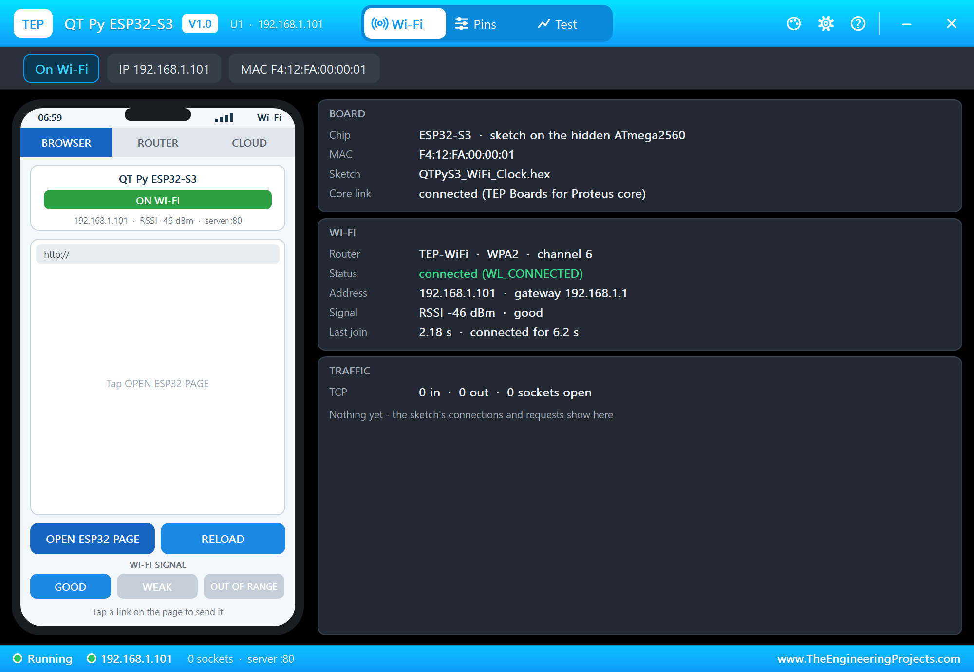
Open the Page
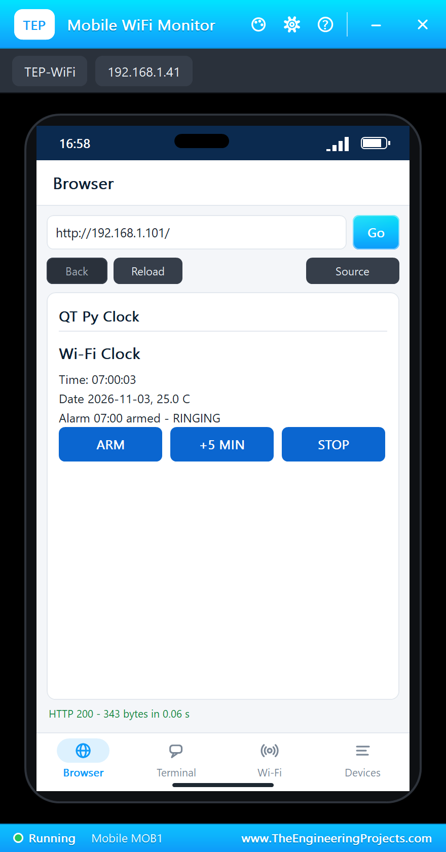
On the laptop click Browser and Go (the home page is http://192.168.1.101/json); on the phone the same with http://192.168.1.101/:
Seven O'Clock
At 07:00:00 the alarm goes off. The display flashes and the NeoPixel flashes red, and the monitor and the page both report it:
Stop, Later and Off
STOP on the phone silences it. +5 MIN moves the alarm to 07:05, as a snooze would. ARM turns the alarm off and the NeoPixel goes blue:
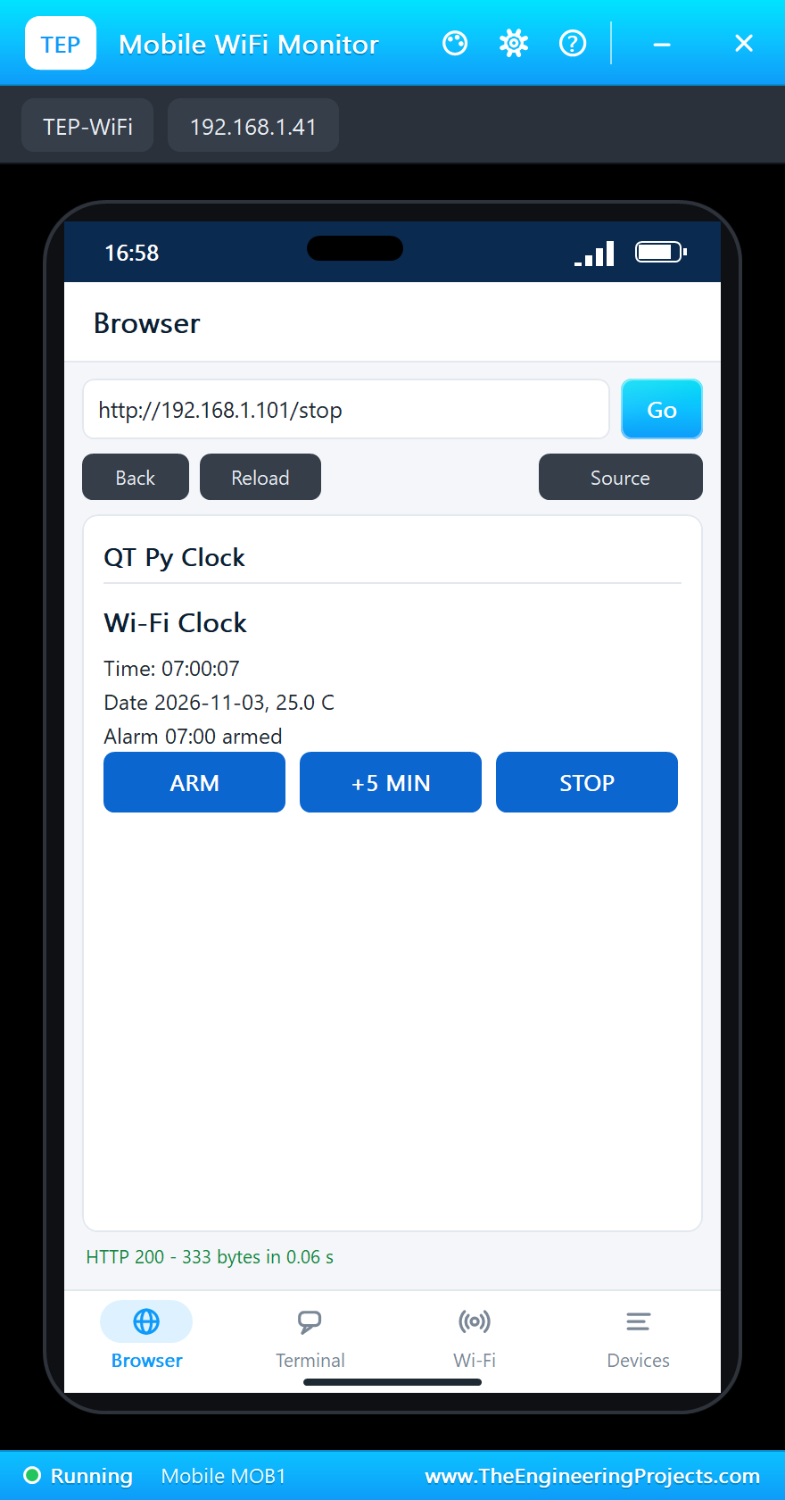
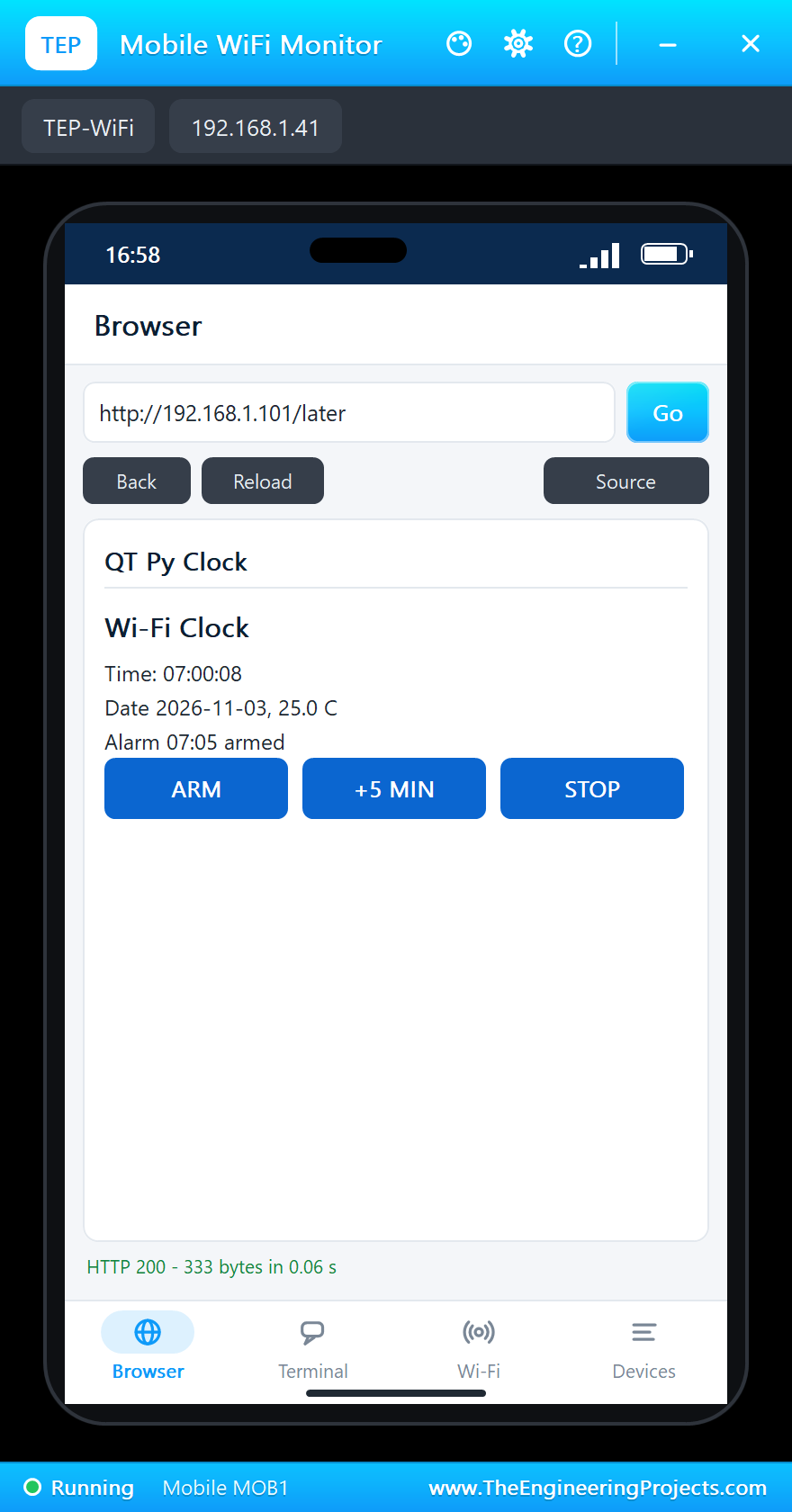
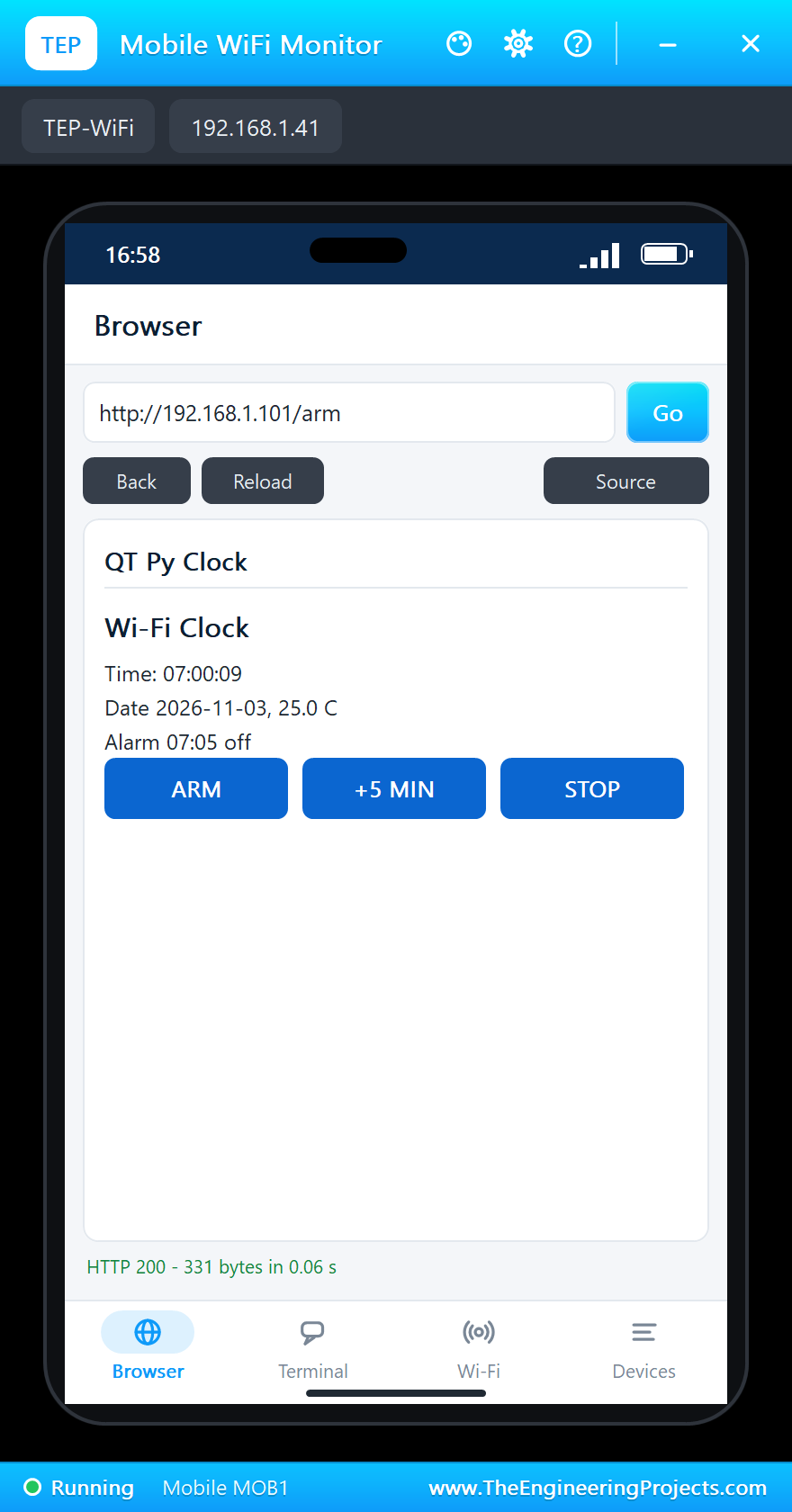
The built-in serial monitor, in the look of our TEP Serial Monitor Advance for Proteus, has followed everything:
Time 06:59:52  25.0 C  alarm 07:00 armed
>> ALARM 07:00:00
Time 07:00:02  25.0 C  alarm 07:00 armed
Alarm stopped (the web page)
Alarm now 07:05
Alarm off (the web page)
Time 07:00:12  25.0 C  alarm 07:05 off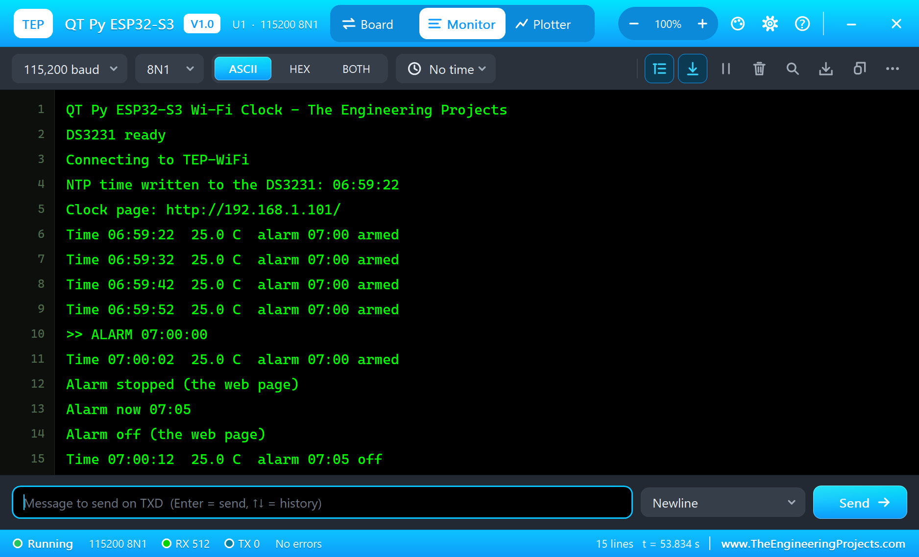
Try It Yourself
- Press the BOOT button on the monitor's Board tab while the alarm rings: it stops.
- Change
UTC_OFFSET_Sto your own time zone and rebuild. - Set the board's TIME property to PC: the clock follows your computer.
- Type
STATUSorSTOPin the monitor.
Ideas to Extend the Alarm Clock
- Sync with NTP once a day, so the DS3231 stays perfect for years.
- Add a buzzer on A2, or a small amplifier, so the alarm can be heard.
- Save the alarm time in the DS3231's own alarm registers, so it survives a reset.
- Show the weather from a web service between the minutes.
Your Own Sketches
Write the sketch in the Arduino IDE with the board QT Py ESP32-S3 (TEP Proteus), use Sketch > Export Compiled Binary and set the board's PROGRAM property to the .hex. For a real QT Py select "Adafruit QT Py ESP32-S3" in Espressif's "esp32" package and upload - the same sketch, with the same names.
Things to Know Before Using a Real QT Py ESP32-S3
- GPIO38 powers the NeoPixel: set
NEOPIXEL_POWERHIGH or it stays dark. - The STEMMA QT socket is a second I2C bus: on the real board it is
Wire1, on GPIO41 and 40, not the SDA and SCL pins. - USB CDC: Serial goes over the chip's own USB; enable "USB CDC On Boot" in the IDE to see it.
- GPIO0 is BOOT: holding it at reset starts download mode, the way out of a sketch that crashes USB.
- Two versions: one has 8 MB of flash and no PSRAM, the other 4 MB and 2 MB of PSRAM; pick the matching board in the IDE.
Properties of the QT Py ESP32-S3
| Property | What it does |
|---|---|
| PROGRAM | the sketch: a .hex from TEP Boards for Proteus (board "QT Py ESP32-S3") |
| WIFISSID, WIFIPASS | the router in range (TEP-WiFi, 12345678) |
| MONITOR, BAUD, AUTOOPEN | the built-in serial monitor: on, its baud rate (115200), open at Run |
| TIME | the clock for NTP: PC or a fixed UTC time (the demo: 2026-11-03 01:59:20) |
Troubleshooting
- "DS3231 NOT FOUND": SDA and SCL on the QT Py's SDA and SCL pins.
- The display stays dark: CLK on A0, DIO on A1, and setBrightness() before the first number.
- The time is wrong: the TIME property sets what NTP answers; PC uses your computer's clock.
- The board stays off the network: the sketch's SSID and password must match WIFISSID and WIFIPASS.
- A number goes wrong above 32767: int is 16 bits in the simulation - use long.
- The page shows old values: use Reload; the monitors do not reload by themselves.
Limitations of the Simulation
- Your sketch gets 8 KB of RAM in the simulation, and there are no FreeRTOS tasks, no second core and no vector instructions.
- Bluetooth LE, the native USB and the STEMMA QT socket as a connector are not modelled: use the SDA and SCL pins.
- The PWR LED, the router, the addresses and the windows are TEP additions.
- QT Py is a name of Adafruit Industries and ESP32-S3 of Espressif Systems; this library is not made or endorsed by them or by Labcenter.
- Tested in Proteus 8.5 in October 2026 (the demo as shipped, about 55 s of simulation). Proteus 7 is not supported.
So, that was all about the Adafruit QT Py ESP32-S3 Library for Proteus. I hope it helps you build and test your QT Py projects before you touch the hardware - NTP, the clock chip, the display, the NeoPixel and the web page in one simulation. If you have any questions, ask in the comments and I will help you out. Till the next tutorial, take care and have fun!