Capacitance Measurement using Arduino
Hello geeks, welcome to our new project. In this project, we are going to make a very useful and interesting electronics tool that we as engineers or tinkers need in everyday life. We use the capacitor in most of our projects for various purposes such as filters or power supplies. Most of the time, we do not have a provision to measure the capacitor value in our digital multimeter. So, this time we came up with the solution. Hence, we will make our own capacitance measurement tool using Arduino.
Rather than investing in new electronic equipment, we will use an Arduino board and some basic components to measure the capacitance. To make this project, we should have some working knowledge about the capacitor. Here, we will not discuss the in-depth working of capacitors, but we will talk briefly so that it would be easy to understand the working principle of our project.
The capacitor is an electronic component that basically stores the energy when applied to an electric field. It has two parallel terminals connected by two parallel conducting plates separated by a dielectric material. Dielectric materials are electrical insulators(resist to pass the current) that can be polarised by applying an electric field. When we connect a battery with the capacitor then due to potential difference, the electric field is created between two oppositely charged plates of the capacitor and this way the capacitor stores the energy.
| Where To Buy? |
|---|
| No. | Components | Distributor | Link To Buy |
| 1 | Capacitor | Amazon | Buy Now |
| 2 | Resistor | Amazon | Buy Now |
| 3 | LCD 16x2 | Amazon | Buy Now |
| 4 | Arduino Uno | Amazon | Buy Now |
Software to install
To make this project, we will need some software to install. As we will make our project in the simulation, so for that we will install Proteus simulation software and for coding, we will use the Arduino IDE.
A brief about Proteus, it is a tool used for simulation and design of electronic circuits. Here we can design different types of electronic circuits and run the simulation. Although Proteus has a very big database for electronic components, still we need to install some libraries which we will use in this project.
- Arduino UNO - We have to install the library for Arduino UNO.
- LCD module - We have to install a library for the LCD module.
You can download this whole project for example Proteus Simulation and Arduino Code, by tapping the below button:
Capacitance Measurement using Arduino
Project overview
In this project, we will use the following components-
- Arduino UNO - We will use this as the main controller for this project. It will calculate the capacitance of the capacitor.
- 16x2 LCD Module - We will use this to show the result of measured capacitance and some user-related messages.
- Resistors and Capacitors - We will be using some resistors to make the RC circuit which is required for measuring the capacitance.
Now let's talk about the working of this project. The capacitance of any capacitor is the amount of charge that is stored in that capacitor and its unit is Faraday (F). To measure the capacitance, we will use some basic properties of the capacitor.
So when we connect a power supply with a resistor across the terminals of a capacitor, it will take a certain amount of time to fully charge. And when we connect any discharging resistor as a load across it, then it will take a certain amount of time to fully discharge. And this charging and discharging time will be proportional to the capacitance of the capacitor and the charging resistor in the RC circuit.
We will use the time constant formula for the calculation of capacitance. The time constant of any capacitor is known as the time taken by the capacitor to charge 63 percent of applied voltage or the time taken by the capacitor to discharge to 33 percent of stored voltage.
Here,
T (Tau) = Time constant(Seconds)
R = Resistance (Ohms)
C= Capacitance (Farads)
Using the above principle, we will charge the capacitor using a resistor to reach the charge of the capacitor to 63 percent of applied voltage and we will measure the time taken by the capacitor to reach that point. As we know the resistor’s value and time constant, using these two, we can calculate the capacitance:
Components required
- Arduino UNO
- 16x2 LCD module
- 10 kOhms Resistor
- 220 Ohms Resistor
- An unknown capacitor(Enter range here )
Components details
1. Arduino UNO
- Arduino UNO is an open-source development board that will be used to measure capacitance.
- It comes with 14 digital I/O pins and 6 analog I/O pins.
- It has 1 UART, 1 SPI, and 1 I2C hardware which are multiplexed with GPIO pins.
- Digital pins can be used for input and output for digital data. In this project, we have used digital pins for charging the capacitor.
- Analog pins have 10 bits of ADC (Analog to Digital convertor) resolution ranging values from 0 - 1023.
- Analog pins can be used for input and output purposes. In this project, we have used analog pins as input for measuring the discharge and charge voltage.
Note-Whenever uploading the code on the Arduino UNO, disconnect any wire which is connected to Rx(D0) and Tx(D1) pins, otherwise, it will give an error while uploading the code.
2. LCD Module
- LCD stands for Liquid Crystal Display, and its display is made using liquid crystal technology.
- For more knowledge of how LCD works, prefer this link Working of LCD display.
- We have used a 16x2 LCD display in this project.
- The LCD module works in two different data modes: 8-bit or 4-bit mode.
- We have used 4-bit mode which means we can send 4-bit data in a single cycle to the LCD module.
- We have used an LCD module to display the user-related information such as capacitance value and the welcome message.
3. Resistors and Capacitors
- Resistors, as the name suggests, is an electronic component that controls the flow of current in a circuit.
- Current flowing in any circuit is inversely proportional to resistance.
- They are used mostly in every type of electronic circuit for current limiting, voltage divider, and in some noise filters.
- There are various types of resistors available depending upon the current rating, manufacturing materials, and use case.
- Although we are making this project in simulation, if you want to make this project using the real components for that we will use the carbon composition through-hole resistors.
- Capacitors are electronic components that have the ability to store energy.
- When we connect any battery across the terminals of capacitors then it will start charging.
- We can store a large amount of charge for a very short period of time in capacitors.
Circuit diagram and Working
Now, we have a list of all the required components. Let's start connecting them.
- Make sure, we have the correct version of Proteus and have installed all the required libraries which we will be using in this project.
- Now let’s start creating the new project in the Proteus.
- Import the listed components to the workspace of Proteus.
- Now we have imported all the components to the workspace.
- First, connect the charging resistor of 10K ohms with the digital pin 8 of Arduino UNO and then connect the discharging resistor of 220 ohms with the digital pin 9 of the Arduino UNO.
- We will use the D8 pin for charging the capacitor and the D9 pin for discharging the capacitor.
- Now connect the capacitor which we want to measure in between these two resistors and connect another terminal of the capacitor with the ground.
- Connect an analog pin of Arduino UNO with the discharging resistor terminal and that analog pin will be A0 on Arduino UNO.
- After that, we are finished with our RC circuit.
- Let’s connect the LCD module with the Arduino UNO, as we are using the LCD module in 4 bits mode so we need to connect only four data pins with Arduino UNO.
- Connect D4 pin to D7 pins of the LCD module with D2 to D5 pins of the Arduino UNO.
- While connecting them, keep in mind that they must be connected in the same order.
- Connect the RS pin with the D6 and Enable pin with the D7 pin of Arduino UNO.
- Connect the RW pin with the ground which enables the write mode in the LCD module.
- Connect the 5v power supply with Vdd and Gnd pins of the LCD module.
- Now we have connected all the components.
- Before moving to the coding part, reverify your connections once.
While working on the real components, make sure you have connected the backlight of the LCD module and set the contrast properly otherwise nothing will be visible on the LCD module.
Arduino code of Capacitance measurement-
Downloading and including libraries
- This project will need the library for the LCD module.
- Before going to write, we must download and include all the required libraries.
- We can download the library for the LCD module using this link LCD module library.
- To include the library, go to the Sketch >> Include Library >> Manage Libraries… Using this, we can add libraries directly by searching the window.
- Or if you have downloaded the library using the link then you will have a zip file for the library. In this case, follow this path: Sketch >> Include Library >> Add .Zip Library…
- After downloading the library, we are all set to start our code.
- First, include the LCD library header at the start, make an object for the same, and declare all the pins which are used for the LCD module.
Variable declaration
- Now we will declare all the variables and pins which we are going to use in this project.
- Declare the charging pin, discharging pin, and an analog pin for measuring the charging voltage as 8,9 and A0 respectively.
- Declare variables to store the start time, stop time, and a variable to store the duration.
- Declare a function “measure()” which will read the analog values.
- After the declaration, we will define a function “measure()”.
- We have defined this at the end of the code.
- This function will read the analog values from the pin and return the values for the same.
- Here, we have declared and defined the function separately but we can define the function without declaring it, but it is not a good practice to do so and sometimes that will cause errors in the code also.
Void setup()
- After declaring all the required variables, we will start writing the “void setup()” function.
- This is a built-in function in the structure of the Arduino sketch.
- We can write any code without this function. As per the structure of the Arduino sketch, this function must be in the code.
- In this function, we will write the pin mode and initialization of other peripherals which will be required in the code.
- This function will only run once when the code starts.
- So in this function, we will first begin the LCD module and print the instructions to use.
- Then set the pin mode of pins and the initial state of the pins.
Void loop()
- This is also a built function of Arduino sketch.
- As per the structure of the Arduino sketch, we can not delete this function from the code even though we don’t have anything to write in this.
- This function executes after the “void setup()” function.
- In this function, we will write our main code which we want to run continuously.
- As the name suggests this will run in a loop.
- Initially, when there is no capacitor connected then the analog value will be in the maximum range and that is 1010 to 1030.
- So now, we will display the message that ‘place a capacitor’ and code will be in a while loop until we connect any capacitor to the circuit.
- Now when we connect any capacitor, the above condition will be unsatisfied, then code will enter in a next infinite while and there we will write the process of charging and discharging of capacitor and time constant.
- First, we will discharge the whole capacitor, for that we will run a while loop, and using the measure() function, we will measure the currently stored voltage in the capacitor.
- And when the stored voltage reaches below or equal to the threshold, we will change the pin mode of pins to start charging the capacitor again and store the start time of charging.
- Using the measure() function, monitor the charging voltage in the capacitor and when the stored charge reaches 63 percent which is 648 of 1023 then we will stop the charging and store the stop charging time also.
- And display the charging percent on the LCD module.
- Now calculate the total time taken by the capacitor to reach the 63 percent of charge and that will be the time constant of the capacitor.
- Using the time constant formula, we can calculate the capacitance of the capacitor as we know the charging resistor connected to the capacitor.
- As we know the charging resistor value is 10k ohms, using that when we divide the time taken by the resistor value, then we will get the capacitance.
- And the calculated result will be displayed on the LCD module for 3 seconds, after that code will enter in an infinite while loop.
- Now we have to reset the device to measure any new capacitor value.
- Here, our coding part will be completed, it is time to test our code with the circuit and now we will move to the next section.
Results and Working
- As we are going to test our project in the Proteus simulation, we have to include the hex file of our code in the Arduino UNO module.
- The first step is to generate the hex file of the code.
- Click on the Arduino UNO module in the Proteus then browse to the location of the generated hex file.
- After adding the code, we are ready to run the simulation and click on the Play button to start the simulation.
- First of all when the code starts, on the LCD module, we will show the range of capacitance that can be measured using this device and the message to place the capacitor if it is not placed already.
- When the capacitor is placed, then the discharging process will start to eliminate any pre-stored charge in the capacitor, thus we will get the more accurate value.
- After 100 percent discharge, the charging process will start and it will go to 63 percent of the stored charge.
- Thereafter, the code will calculate the capacitance using the time constant formula, and the result will be displayed on the LCD module with the message to reset the device to measure again.
- After the compilation of the simulation, click on the stop button to stop the running code.
I hope we have covered all the points related to this project such as circuit diagrams, codes, and working simulation. And I think this will be a very useful project for your daily tinker life. Please let us know if you face any difficulties while making this project in the comment section below.
We will be happy to hear if you will make this project used in your projects.
Thanks for reading this article. All the best and see you in the next project.
Car Parking System with Automatic Billing using Arduino
Hi Geeks, welcome to our new project. Our new project is one of the most common issues you’ve seen in your cities. In this project, we are going to make a car parking system with automatic billing. In the entire world, there are an estimated 1.4 billion cars on the road, which is absolutely great news if we are considering the development of the Automobile industry. But the most serious issue is that the number of cars exceeds the number of available parking places, resulting in traffic congestion. Damaged cars due to this lack of space, fewer parking locations, lack of parking signage, informal parking, and overcharging for parking are just a few of the issues.
People are still choosing manual parking methods, which have a number of drawbacks, such as searching for a vacant spot in a parking lot without knowing if the lot is full or not, resulting in time and fuel waste. Vehicle safety is also a concern that may be addressed. We've all been in a position when we've spent a long time looking for parking at a location just to discover that none is available. You would think that if you knew the slots were full, you would've ended up finding another parking spot.
Based on these scenarios, we came up with the idea of a Car Parking System with Automatic Billing which will also reduce manpower such as security, booth attendants, etc., required in parking lots. Everything in the modern day is automated, and with this project, we can automate this procedure using simple electronics components and Arduino. Let's get started.
Software to install:
Instead of using real components, we'll use the Proteus Simulation tool to design this project. It's also a good habit to experiment with simulations before attempting to build everything with real components. By simulating an issue that may develop when working on actual components, we may identify the problem and avoid any damage to our components.
Proteus is an interesting software that lets you model and build electronics circuits. Despite having a huge library of electronics components, Proteus software lacks pre-installed modules such as Arduino boards, Ultrasonic sensors, RTC modules, LCD modules, and so on.
Now, we’ll start installing the libraries, which is needed for our project:
By clicking the button below, you can download the entire project, including Proteus Simulation and Arduino Code.
Project Overview:
These are required components for Accident Detection, which are as follows:
- Arduino Uno: Arduino Uno is a development board from the Arduino family, which is the main component of this project and acts as the brain. The Microcontroller i.e., Arduino is responsible for the decisions that are going to be processed in the project.
- 20X4 LCD display: It is used to display the information regarding parking slots and shows the amount that has to be paid by the driver at the Check out time from the parking lot.
- Ultrasonic Sensor: It is used to calculate the distance from the car to the entry gate and detects that a car has reached near the gate.
- RTC Module: Real-Time Clock Module is used to calculate the time and plays a key role in determining the total amount for the parking slot.
Components Needed:
- Arduino Uno
- LCD Module
- Ultrasonic Sensor
- Keypad 3x4
- LED’s
- RTC Module
Components Details
Arduino Uno:
- Any Arduino development board can be used in this project, however, we'll be using Arduino UNO development boards. The Arduino UNO is a programmable, open-source microcontroller board from the Arduino series.
- It contains an ATMega328P microcontroller from Atmel, which has an 8-bit RISC processing core and 32 KB of flash memory.
- The Arduino UNO includes 14 digital I/O pins i.e., D0 - D13, with a resolution of 10 bits, including 6 PWM pins and 6 analog I/O pins (0-1024) i.e., A0 - A5.
- Only one hardware UART peripheral pin, one I2C peripheral pin, and one SPI peripheral pin are available on the Arduino UNO (however we can use other pins for UART communication using the SoftwareSerial package in Arduino).
- The Arduino UNO can be powered from a voltage range of 7 to 12 volts, the voltage regulator embedded inside the board will reduce the excess voltage. however, not more than 9 volts is suggested since it might harm the Arduino board.
- A USB-B cable (the same cable that we used to upload the sketch to Arduino UNO), a DC power jack, and the Vin pin on the board may all be used to power Arduino UNO.
- Using the Arduino IDE Software, the sketch is written and uploaded to the Arduino UNO. It is completely free, simple to comprehend, and easy to combine with a variety of electronic components.
LCD Module:
In this project, an LCD display is used to present the information to the user.
- LCD stands for Liquid Crystal Display, and it is a type of display that is made using Liquid Crystal technology.
- LCDs come in a variety of sizes; in this project, we utilized a 20X4 size.
- The 20X4 indicates that it can show 80 ASCII characters at once.
- The LCD has 16 pins. In which the necessary pins are connected in the circuit.
- It contains eight data pins, one Read/Write select pin, one Register mode pin, one Enable pin, two backlight pins, two power supply pins, and one contrast control pin.
- In the LCD, there are primarily two types of registers: Command Register and Data Register.
- When the RS(Register Select) pin is set to logic high, the data register mode is selected, and when it is set to logic low, the command register mode is selected.
The RS pin will be set to logic high to display the data on the LCD.
Ultrasonic Sensor (HR-SR04):
- The HC-SR04 ultrasonic sensor employs SONAR to estimate the distance of an object.
- The ultrasonic sensor sends out a signal wave that has a frequency of about 40 kHz, with a high pitch that humans are unable to hear.
- From 2 cm to 400 cm (1" to 13 feet), it provides the detection of objects with high accuracy and the pulse will not be disturbed by sunlight or any climate conditions.
- It consists of four pins, Trig, Echo, VCC, and GND.
- The operating voltage of an Ultrasonic sensor is 5V. We can connect the VCC pin of the sensor with 5V output in Arduino and the sensor will work perfectly.
- Ultrasonic sensors work on the principle of sound wave reflection.
- The trig pin works as an ultrasound transmitter which emits the high frequency sound waves in pulses. And the echo pin works as an ultrasound receiver. It receives the reflected ultrasonic waves which are bounced back from the object.
- We calculate the distance from the object and the sensor by measuring the time taken between the transmission and the reception of the signal.
- To measure the distance of sound traveled from trig to echo,
Distance = (Time x SpeedOfSound) / 2.
Speed of Sound: 340 meters per second i.e., 0.034
- The easiest way to calculate the distance in cm is using this formula,
Distance in Centimeters = (( Time taken by pulse signal (in microseconds) / 2) / 29)
Keypad 3x4:
- A keypad button is used for user input.
- The keypad's buttons are arranged as a matrix of 3x4. Which means it has four rows and three columns.
- They work on the principle of membrane keypads. They are very flexible and feel like a push button.
- The switch between a column and a row trace is closed when a button is pressed, allowing current to pass between a column pin and a row pin.
- A copper padding and line beneath the pad connects each switch in a row to the other switches in the row.
RTC Module (DS1307):
- The DS1307 IC is a low-cost, high-accuracy RTC that uses the I2C protocol as an interface.
- The DS1307 features a backup battery mounted on the rear of the module to maintain track of time even if the main power supply is disconnected.
- When necessary, the chip shifts between the primary and backup power sources.
- The RTC records information such as seconds, minutes, hours, days, dates, months, and years.
- This module includes a Reference clock, programmable Square wave output(SQW), SCL, SDA, VCC, and GND.
- Automatic Power-Fail Detect and Switch Circuitry
- Low Power Operation Extends Battery-Backup Run Time.
- The RTC module works on operating voltage 5V.
Proteus Simulation of Car Parking System:
Now, it’s time to start the design of the Proteus Simulation of our Car parking system
- Before you begin designing, make sure Proteus is installed on your computer and that you have downloaded all of the necessary libraries.
- We'll need Arduino libraries and LCD modules for this project. Make sure you've read the section on using libraries in Proteus software.
- Let's begin by creating a new project, and importing all of the required components, and placing them within the working area.
- Select all of the components from the Proteus component library that we'll require.
Circuit Diagram and Working:
After importing all required components to the workplace, let’s move to connecting them.
- Starting with the connection of LEDs, we are using digital pins 2,3,4,5,6 for LEDs. Connect the positive side of the LEDs to the Arduino UNO board.
- After that, connect the Ultrasonic sensor module’s Trig pin and Echo pin to digital pin 8 and 7 respectively, Vcc to 5v volt power and GND to Ground.
- In the simulation. it will not be possible to change the distance from the Ultrasonic sensor so for that we have connected a potentiometer with the test pin of the module.
- Now start the connection of the Keypad, as this is a 3x4 keypad so it will use 3 pins for columns and 4 pins for rows.
- As there are limited digital pins on Arduino UNO, we have to use the analog pins of Arduino UNO as digital pins.
- Now let’s connect the row pins A, B, C, D with A0, A1, A2, A3 respectively and column pins 1, 2, 3 with digital pins 9, 10, 11 respectively. And we have to connect the pins in an exact manner.
- RTC module uses the I2C protocol, so we will connect SDA and SCL pins to Arduino UNO’s SDA (A4) and SCL (A5) pins respectively. Vcc with 5v power supply and Gnd with the ground.
- As there are no pins left for connecting the LCD module therefore we will use an I2C GPIO expander for connecting the LCD module.
- Connect the SDA and SCL pins of GPIO expander with the SDA and SCL pins of Arduino UNO and we have to set the slave address of GPIO expander, for that we will connect the A0, A1, A2 pins with ground, that will set the I2C slave address to 0x20.
Now we have done the circuit, it’s time to move to the coding side of this project.
Arduino code for the accident detection:
- We must add relevant libraries, which operate as header files in programming languages before we begin writing the code.
- So, if the necessary libraries aren't already installed in the Arduino IDE, we'll need to download them first.
- We can install Arduino libraries by going to 'Sketch > Include Library > Manage Library' in the Arduino IDE. In the library manager, we can now search for our essential libraries. The libraries can also be installed via zip files.
- We can download the libraries from the above instruction, but if they are not available, we can use the following links to download the zip files of libraries.
- Here we used “Wire.h” to enable I2C communication and it is pre-installed.
- “LiquidCrystal_I2C.h” is used for the LCD.
- “Keypad.h” is used for the integration of the keypad module.
- “RTClib.h” is the library for RTC modules.
- Let’s declare the pins for modules. We mainly use two pins i.e. Trig and Echo for the object detection and distance calculation. Here we have connected the Echo pin to D7 and Trig pin to D8 in Arduino Uno and an array for storing the pins for LEDs as D2, D3, D4, D5, D6. Two arrays for storing the pins for keypads such as rowPins for A0, A1, A2, A3 pins and colPins for D9, D10, D11.
- Now, Let’s declare configuration related variables for the keypad. Here we are declaring variables to store the number for Rows and Columns. We will use a 2D char array named ‘hexaKeys’ for storing the symbols of keypad.
- Now declare some general variables for storing the values for ultrasonic sensors, charge, total charged amount, check-in time and check-out time of vehicles.
- Now, Let’s declare the objects of the modules.
- The “customkeypad” is initializing an instance of class NewKeypad. The statement is going to map these symbols with the pins we have declared to connect with Arduino. Hence, it will map according to the row and column pins.
- Next, we are initializing the LCD display with an I2C serial interface and setting the address to 0x20 Hex.
- And we are declaring an object named ‘rtc’ for the “RTC_DS1307” module.
Void Setup():
- The void setup() is an important function in the sketch that will execute only once in the whole program. The input, output, and other serial communication initializations are done inside the void setup. Let’s write the void setup sketch now.
- In this setup function, firstly we have enabled the serial communication with “Serial.begin” with the default baud rate of 9600.
- Next, we are initializing the LCD and turning on the backlight of the LCD.
- We have already declared the Trig and Echo pins before in the declaration part, and now we are going to set them up as output and input pins respectively.
- There may be a doubt why we have declared a Trig as output and Echo as input. That is because the Trig pin will generate the ultrasonic wave pulses and the Echo pin will work as a receiver for reflected waves.
- We are using five led’s for the five slots in the parking lot and to make the logic simpler, declare the led pins as output mode.
- Now, we are printing a line in the serial monitor and LCD. We are using the cursor function and printing “Made by” in the first row and “Tushar Gupta” in the second row. (0,0) is representing (column, row) in the LCD.
- After printing the line, clear the LCD screen.
- Now, we are trying to initialize the RTC module and if the RTC is not found, it will print that “Couldn’t find RTC”. and halt the further processing of code.
- After successful initialization of the RTC module we will know if the RTC module is running already , if yes then we don’t have to set the time explicitly otherwise we have to .
- We will use a “dist()” function to calculate the distance using the formula mentioned in component details.
- For the calculation of distance, we will generate the pulses using the Trig pin.
- To generate the pulses , switch the TRIGpin to LOW for 4 microseconds and then HIGH for 10 microseconds then again LOW .
- By using ‘pulseIn’ we can calculate the time duration the wave has taken to travel back from the object.
- “ distance = duration*(0.034/2); ” and here 0.034 is the speed of sound and with this formula, we can calculate the distance in cm and set the threshold values.
- “pulseIn” takes two arguments, first pin number and second logical state. This will read the pin for logic HIGH and return the time period in which that pin was at a HIGH state.
- For more knowledge of “pulseIN “ refer to this link: pulseIN function
Void loop():
- It is the next most important function of Arduino code/ sketch. The “void loop()” will run after the execution of “void setup()”.
- We'll write the code required to run in a continuous loop in this part. So here we'll write our main application code.
- Here, we are going to first discuss the Automatic billing part near the gate in our parking system.
- In the loop function, the Date and Time of that current time are set by “rtc.now”, and the user will enter his slot number in the keypad when he/she is exiting from the slot.
- The user will click the allocated slot number on the keypad and we are collecting that in the “customkey” variable using the “getkey” function.
- The serial monitor will print the custom key entered by the user. Then we will check the slot status by “digitalRead (led[i])”.
- If the led status is HIGH which means the slot was occupied now we will generate the bill for that slot and display that amount on the LCD display for1 second after clear the LCD and set that slot LED to LOW state.
- The next step we are going to do is to calculate the total amount according to his vehicle staying inside the parking lot. And for that, we can do the simple calculation that is “amount = charge*(gotime [i] - cometime [i]) ;”.
- We have already declared the charge amount in the above sections of the program. The charge will be multiplied by “go time - come time”, which is the total time the vehicle stayed inside the lot. And the multiplied result of stay time and charge is the final amount the driver has to pay for his parking slot.
- Now, the driver can pay the amount and exit through the gate. Here, after a second delay, we are clearing the LCD display.
- “What if the driver pressed any wrong key which has a free slot?” That might be the question in your mind. Well, we can cover that condition with an else statement, where we can print “The slot is already empty” on the LCD and let the driver know that he has entered the wrong key in the keypad near the exit gate.
- Till now, we have seen the Automatic billing logic near the exit gate. But let’s see what is the slot allocation process at the entry gate.
- As we have already calculated the distance with the ultrasonic sensor using the “dist()” function, we can set the distance limit to 100cm before the gate, and when a car reaches the entry gate the allocation of the slot will be started.
- The “for loop” here will see what are the slots showing Low/empty in the parking and allocate that empty one to the car by printing “Park your car at ” and “Slot i” in the LCD.
- As this slot was allocated, we have to write this LED as High which indicates the slot is not empty. This is the reason where the slot led is high at the exit gate when the user pressed his slot number in the keypad. We are turning on the LED when we are allocating the slot to a car.
- Now we also have to collect the “come time” by the RTC module for further calculation at the end or near the exit gate.
- We are implementing an if statement where the all LEDs are high, which means all the slots are filled, the LCD should print (“No more slots”) and inform the driver and clear the LCD screen.
Results / Working:
We have completed the Proteus simulation circuit and Arduino code for the Car Parking project. And it is ready for testing.
- Before going to start the simulation, we have to add the hex file of our application code in the Arduino UNO module in Proteus and a hex code for the ultrasonic sensor also.
- To add the hex file, click on the Arduino UNO and a new window will open then click on the Program files, there we will browse to our hex file.
- In the same way, we can add a hex file for the ultrasonic sensor.
- Now start the simulation, on the first boot of the circuit, LCD will display the welcome message and the same message will be displayed in the serial terminal also
- Just for debugging purposes, we are continuously printing the ultrasonic sensor values.
- In the simulation to change the distance between the vehicle and ultrasonic sensor we have used a potentiometer. Now change the value on the potentiometer.
As we can see that for 50% value on the pot ultrasonic sensor value is near to 500 cm and for 77% value on the pot ultrasonic sensor value is near to 850 cm.
- Let's test the condition when the vehicle approaches the sensor, to satisfy that condition the object must be at a distance of less than 100 cm. For that, we have to change the pot value. Set the pot value near to 10 %.
- After that LCD will display a message if that spot is vacant like “Park your car at Slot 1” and LED for the same location will glow.
- To take the bill for any location press the keypad for that location number let’s suppose here the location is 1 so we will click on ‘1’
- After that, it will generate the bill with the total charged amount and the LED for that location will be turned off.
- In case if we click any slot button which is already vacant then LCD will display the message for the slot is vacant.
Here it is not visible which button on the keypad has clicked but suppose we have clicked ‘1’ and if that location is vacant then it will display that message.
- Let’s take another case when we want to park another car. Now slot 1 is already busy so we will park at slot 2.
- This time when the sensor value changes less than 100 cm, then the LCD display will show “Park your car at slot 2” because slot 1 is preoccupied.
- In the image, we can see that both LEDs are glowing as both slots are occupied now.
- For billing, we will click the button on the keypad for the respective slot.
- Let’s take a case when all slots are occupied. Here we can see all slot LEDs are glowing.
- Now we will try to park another car. Then LCD will display ‘no more slot’ as there is no vacant slot available at parking.
I hope you have a good understanding of how our Car parking system project works and that you have liked it. Although it’s a tough nut to crack in the first read, I strongly recommend you to read the logic part twice for better understanding. I believe we have covered almost everything, please let us know if you have any questions or suggestions in the comments section.
Thank you very much for reading this project. All the best for your projects!
Accident Detection System using Arduino
Hello everyone, Welcome to our new project. Our new project plays a very important role in our daily life as it is directly connected to our lives. In this project, we are going to design an Accident Detection module. Accidents are the most common thing we hear about in the news, and in social media. Everyone here or there has seen accidents or has been with one. So when any such incidents happen, we inform respective stations or hospitals in that emergency situation. But what about the accidents that happen at night, or in places where there is very less crowd or you are alone. So, to address this issue and provide a potential solution for that, we are going to learn how to detect an accident automatically and inform nearby aid/help stations.
We can use this useful project for an engineering project’s showcase for electronics, electrical engineering students, and can be used in real-life situations where it can help people in disastrous situations.
According to WHO, research says that in the current scenario, 1.3 million people are the victims of road traffic crashes, and 40% of these accidents of all fatal accidents occur at night. In most cases, the accidents are not reported immediately, or the injured doesn’t receive any help during that time. The time between the accident and the arrival of medical help for the injured can sometimes make the difference between his life or death. In the future, we can interface with the vehicle airbag system. This will optimize the proposed technology to the maximum extent and result in the finest accident detection system possible. In this Modern era, everything is being automated and with this project, we are going to automate this process with some electronic components and Arduino. So Let’s dive in. Here's the video demonstration of this project:
| Where To Buy? |
|---|
| No. | Components | Distributor | Link To Buy |
| 1 | NEO-6M | Amazon | Buy Now |
| 2 | SIM900 | Amazon | Buy Now |
| 3 | Arduino Uno | Amazon | Buy Now |
Software to Install:
Instead of using real components, we will design this project using Proteus Simulation. Working with simulation before attempting to make it with real components is also a smart practice. We can figure out the issue that may arise while working on real components and avoid any kind of damage to our components by simulating it.
Proteus is a very fascinating tool that allows us to simulate and create electronic circuits. Despite the fact that Proteus software contains a large library of electronics components, it still lacks pre-installed modules such as Arduino boards, GPS or GSM modules, and so on.
Let’s install the required libraries which, we are going to use in this project:
You can download this whole project for example Proteus Simulation and Arduino Code, by tapping the below button
Accident Detection System using Arduino
Project Overview:
These are required components for Accident Detection, which are as follows:
- Arduino Uno: Arduino Uno is a development board from the Arduino family, which is the main component of this project. The Microcontroller i.e., Arduino is responsible for the decisions that are going to be processed in the project.
- Accelerometer: An accelerometer is a device that measures acceleration, which is the change in speed (velocity) per unit time. By measuring acceleration we can get information like object inclination and vibration which helps in detecting unusual activities/ accidents.
- GSM: A GSM/GPRS Module is a device that is actually responsible for the wireless communication with the GSM Network, in this case, it is responsible for sending the appropriate information to rescue stations.
Components Needed:
- Arduino Uno
- GPRS Module
- Accelerometer
- GSM Module
- Bread Board
- Jumper Wires
Component details:
Arduino Uno:
- The Arduino UNO is one of the Arduino family's programmable, open-source microcontroller boards.
- It includes an Atmel Microchip ATMega328P microcontroller with an 8-bit RISC processing core and 32 KB flash memory from Atmel.
- It has 14 digital I/O pins, including 6 PWM pins and 6 analog I/O pins with a resolution of 10 bits (0-1024).
- It comes with one hardware UART, one I2C, and one SPI peripheral.
- We can use the Arduino UNO with a voltage range of 7-12 volts, but not more than 9 volts is recommended because it may damage the Arduino board
- To power the Arduino UNO we can use a USB-B cable (the same cable that we use to upload the sketch to Arduino UNO), a DC power jack, or the Vin pin on the board.
GPS Module:
- The Global Positioning System (GPS) is a space-based global navigation satellite system that gives accurate location and timing in all weather and at all times around the world.
- It sendLongitude, latitude, height, and time are the four variables that a GPS receiver determines.
- Data determined by the module will be sent to the microcontroller (Arduino Uno) through the UART protocol.
- With a USB interface, the GPS module is simple to operate. It operates on a 3.2 to 5V supply range, allowing it to interface with both 3.3V and 5V microcontrollers.
- It has a default baud rate of 9600 and can be modified as per our requirement.
- We have used this to get the current location of the user.
Accelerometer:
- Accelerometer sensors are integrated circuits (ICs) that are used to measure acceleration, inclination, and various parameters regarding the x,y,z axes. It is the main component to detect the accident.
- Here we used the MEMS (Microelectromechanical Systems) accelerometer. These types of accelerometers are used where we have to measure the vibration or shock without any fixed reference.
- It monitors changes in the capacitance and converts that value to analog output voltage.
- Gyro Range of the Accelerometer sensor is ± 250, 500, 1000, 2000 °/s (may vary depending upon the sensor).
- Accelerometer Range of the sensor module is ± 2 ± 4 ± 8 ± 16 g (may vary depending upon the sensor).
GSM module:
- This module is used to send the notification to the rescue station or the emergency numbers.
- It communicates with the Arduino UNO using the UART protocol.
- It works in a voltage range of 3.5 - 5 volts.
- There are different types of GSM modules available but in this project, we have used the SIM900D module.
- We operate them using the AT commands. As there are hundreds of AT commands but we will use some basic only just to send the message.
Proteus Simulation of Accident Detection Circuit:
Now, it is time to start designing the main circuit of Accident detection in Proteus Simulation software.
- Most importantly, ensure that Proteus is installed on your PC/Laptop and download all the required libraries for Proteus ahead of starting the designing steps.
- For this project, we are going to use libraries for Arduino Uno, GPRS Module, GSM module.
- To add the libraries in the Proteus suite we have to go to the C drive then LabCenter Electronics >> Proteus 8 professional >> Data >> Library and paste the downloaded library files here.
- The download links of all the libraries have been provided to you in the above sections, please go check them out.
- Let’s start the making of a new project, open the new project in Proteus.
- After that enter the name of your new project.
- Now our working area will be open here we will import all the required components which we are going to use.
- The following components need to be selected from the Proteus component library. We’ll connect the components and make the circuit complete.
- Now we have imported all the required components for this project, after this, we will start connecting them.
Circuit Diagram and Working:
- There are two modules GPRS and GSM modules, both communicate using the UART protocol but in the Arduino UNO there is only one hardware UART’s provision. Now, you may have doubts about how we are going to connect them. No worries, we will handle that on the coding side by declaring the different pins as UART pins.
- We can use different pins for UART using the SoftSerial library of Arduino, which will be discussed in the code.
- We will use the digital pins for UART connections, digital pins 2 and 3 for communication of the GSM module, which means connecting the Rx and Tx of the GSM module with the D2 and D3 pins of Arduino UNO respectively.
- Connect the Rx and Tx of the GPRS module with the D10 and D11 pins of Arduino UNO respectively.
- As modules are connected, now we will connect the accelerometer. As it will not be possible to simulate the accelerometer in Proteus so we have used the potentiometers to change the value of the X-axis, Y-axis and Z-axis.
- You may have doubts about how we can replace the accelerometer with potentiometers. As we will use the MEMS accelerometer, which sends the analog voltages for each axis, so we can simulate that using the potentiometer because we will receive the same type of data.
- We need three potentiometers, one for each axis. Potentiometers of the X-axis, Y-axis and Z-axis will be connected to A1, A2 and A3 pins of Arduino respectively.
- We will connect a serial terminal for debugging purposes.
Arduino code for Accident Detection System
Before going to start the coding, it would be easy if you understood the circuit diagram connections.
- When we start writing the code(called a sketch in Arduino IDE), we will first include all of the necessary libraries for this project.
- So, if the essential libraries aren't already installed in the Arduino IDE, our first step would be to get them.
- Here we use mainly two libraries, one for serial communication and parsing data from the GPS module.
- By heading to 'Sketch > Include Library > Manage Library' in the Arduino IDE, we can install libraries related to Arduino. We can now search for our essential libraries in the library manager. We can also use zip files to install the libraries.
- As we've installed all the specified libraries. Let’s include them in our sketch.
- Now, we are declaring D2 and D3 pins for serial communication with GPRS modules and declaring GPS objects as well, which will pretty much do all the grunt work with the NMEA data.
- After that, we will declare variables to store the GPS module data.
- Now, we are declaring pins and variables for the accelerometer which we will use in our project. Here, we are using Analog Pins because we are reading the analog voltages from the potentiometer.
- We need to declare two threshold values for change in acceleration when an accident is detected.
- The min and max values can vary. So, it is highly recommended to measure the values by accelerometer for devices using.
Void Setup():
- It is one of the most important functions which will execute only once in the whole process.
- As we are using a GPS module in our project, We should first start serial communication between the components and Monitor them through “Serial Monitor” in the Arduino IDE.
- “Serial.begin” is used to set up the serial configuration for the device which is connected to the Serial Port of the Arduino. Here, we will set the baud rate for that device i.e 9600 in our case.
- “serial_connection.begin(9600)” is used to set up the UART configuration for the GPS module. As the GPS module communicates to the Arduino at the baud rate of 9600.
- We are using an Accelerometer in the circuit and it was clearly explained in detail that it will sense the x,y,z coordinates of the device and send them to Arduino.
- Here, we have initialized a for loop to collect the sample data for x, y, and z coordinates of the device in the ideal state.
- Afterward, the sample coordinates have been successfully measured by the Accelerometer sensor, but we need an average value for smoothing the sample coordinate values. So here, we will calculate the average of each coordinate and print them in the serial monitor.
- After the setup, we will write our main application code in the Void loop function.
Void loop():
- It is the second most important function of Arduino code. It will come to action after the execution of “void setup()”
- We'll write the code required to run in a continuous loop in this part. So this is where we'll write our primary application code.
- As a result, when the code gets to the void loop portion, We firstly take the NMEA data from the GPS module and print it in the serial monitor.
- Wait a minute, NMEA??, I can understand all the questions in your mind. Let us give you a simple explanation regarding NMEA and its applications.
- The word NMEA stands for the National Marine Electronics Association, which is a mode of communication that existed before inventing GPS. NMEA-format GPS data can be accessed with a wide variety of GPS receivers, instead of creating a new custom interface every time. Thus, it makes our lives easier using the GPS Module.
- When we are printing the NMEA data into the serial monitor, it will be printed in a specific structure. This NMEA data was output from a GPS receiver:
“$GPGGA,191605.00,4521.7785210,N,07331.7656561,W,2,19,1.00,674.354,M,19.900,M,0.90,0000*60”
- All NMEA signals start with the ‘ $ ’ character and for every data field such as coordinates, and various parameters are separated by a comma. The data further includes Timestamp, Latitude, Longitude, Quality indicator, Number of satellites involved, Altitude, etc., which is not necessary to remember. Make sure to get the data from the GPS module. If we have succeeded in this step and get the data on the serial monitor, then we are good to go for further processing.
- The “if” statement is to process the NMEA data and separate the data into the required format if there is any location updated to the GPS receiver.
- As we have already received NMEA data in the previous step, the data will be separated into Latitude, Longitude and Altitude.
- In the Loop function, the values of GPS and accelerometer will be continuously tracked.
- Here, the analog values of x,y,z coordinates are being measured and printed in the serial monitor.
- These are not the values we measured in the void setup, those were the values to take the readings in the ideal state of the device.
- But in the loop, the values are the present x,y and z coordinates measured by the accelerometer.
- This is the condition for accident detection, we have already discussed before that in the void loop the x,y,z coordinate values are continuously extracted and the “if” statement here compares the recent values with fixed min and max values of the coordinates.
- If the recent values are indistinct or do not match with threshold values i.e., max value and min value, then it indicates that an accident has been detected.
- When the accident detection condition is satisfied, the GPRS module will be activated and will call to rescue stations for aid/help and their home.
- Here, we have programmed to give a call 5 times to the appropriate numbers in the “for” loop.
- And the process also includes a messaging feature along with calling to rescue stations.
- When the same accident condition is satisfied, the messaging feature will be activated and we are going to send the alerting message including the Location, Latitude, Longitude, and Google map location link by appending latitude and longitude values the to respective numbers.
Results / Working:
We have successfully completed our Accident detection project and it’s ready to test!
- Before going to start the simulation, we need to import the hex files of Arduino code in the Proteus, to do so click on the Arduino and browse to the hex file of the code and select.
- Now we need to add the program files for the GPS and GPRS modules.
- Here we should note that we only need to upload the program files for the modules while we are working in simulation. In the real modules, they come up with pre-installed codes.
Now we have done all the prerequisites of simulation.
- Let’s power the circuit and start the simulation, firstly the void setup function will run and it will initialize all the required pins and variables and will read the ideal state values of the potentiometer.
- Now to simulate the accident case, we will change the values from the potentiometer, so when the potentiometer’s value changes and the falls in the Min and Max value range the if condition will be stratified.
- After this GSM module will call the stored number 5 times and send the GPS location with Google maps link in that.
- We have used some serial monitors for debug purposes, you can see the current state of the project using them.
I hope you have a good understanding of how our Accident Detection project works and that you have liked it. Although I believe we have covered almost everything, please let us know if you have any questions or suggestions in the comments section.
Thank you very much for reading this project. All the best for your projects!
Smart Coffee Vending Machine using Arduino
Hello geeks, Welcome to our new project. As most readers have already seen the coffee vending machine or maybe you are drinking coffee while reading this article and if you are a tinker or a geek, it must have come to your mind how to make a coffee vending machine on your own. In today's tutorial, we are going to learn how to make a Smart Coffee Vending Machine using Arduino with Proteus Simulation for the same.
We can use this project for an engineering project’s showcase for electronics, electrical engineering students, and can be used in offices as well.
Coffee is the second most popular drink in the world and it is one of the oldest beverages of the world. According to Wikipedia, more than 2 billion cups of coffee are consumed every day in the whole world. As engineers or working professionals, we all know how coffee is very important for us. Having a good coffee makes our day better and refreshes the mood. Research shows coffee drinkers tend to live longer but when keeping it in moderate consumption. And making a good coffee is one of the most skillful jobs and time-consuming processes as we want our coffee in minutes. Now here our project comes to the picture, this smart coffee vending machine can make a good coffee in a couple of minutes. There are various flavors of coffee and our smart coffee vending machine can provide us with 4 different flavors which are the most commonly loved such as Latte, Cappuccino, Espresso, and Cafe Mocha. Here's the video demonstration of this project:
| Where To Buy? |
|---|
| No. | Components | Distributor | Link To Buy |
| 1 | DC Motor | Amazon | Buy Now |
| 2 | LCD 20x4 | Amazon | Buy Now |
| 3 | Arduino Uno | Amazon | Buy Now |
Software to Install:
As we are going to design this project using Proteus Simulation, instead of using real components. As in the simulation, we can figure out the issue which may occur while working on real components and that can damage our components.
Proteus is the software for simulation and designing electronics circuits. As Proteus software has a big database of electronics components but still it does not have few modules in it like Arduino boards or LCD modules etc.
So we have to install the libraries, which we are going to use in this project:
- Arduino Library for Proteus: We have to add the Arduino boards to the Proteus components list.
- LCD Library for Proteus: We have to add the LCD module to Proteus Suite.
You can download this whole project for example Proteus Simulation and Arduino Code, by tapping the below button
Smart Coffee Vending Machine using Arduino
These are required components for Smart Coffee Vending Machine, as follows:
- 20X4 LCD display: It is used to display user-related messages like the state of the vending machine.
- Arduino UNO: It is used as the brain of our project. All operations and decision-making will be done using this microcontroller.
- DC motor: It is used for dispensing the ingredients of coffee and the mixer.
- Buttons: It is used as a user interaction option.
As a suggestion, whenever we make a project, it should be like a product, as it should be user friendly and interactive, so considering that we have used an LCD module to display the messages related to available coffee flavors and their individual prices so that users can easily select them using buttons and DC motors to pour the ingredients related to coffee like water, sugar, coffee powder, and milk, and a mixer for blending the coffee.
We have connected the LCD using an I2C GPIO expander as we have limited GPIO pins to connect other peripherals with Arduino UNO. I2C Gpio expander requires only two pins as we know that I2C uses SCL(Serial Clock) and SDA(Serial Data) pins for communication.
Components Needed:
- Arduino UNO
- LCD display
- 4 Buttons
- 8 Motors
- PCF8574
Components Details
Arduino UNO:
We can use any Arduino development board but here in this project, we have used an Arduino UNO board.
- Arduino UNO is one of the programmable, open-source microcontroller boards of the Arduino family.
- It contains an Atmel’s Microchip ATMega328 or ATMega328P microcontroller which has Harvard architecture 8-bit RISC processor core and 32 KB flash memory.
- Arduino UNO comprises 14 digital I/O pins out of which 6 are PWM pins as well and 6 Analog I/O pins with 10 bits resolution(0-1024).
- Arduino UNO has only 1 hardware UART pin(but we can use other pins also for UART communication using SoftwareSerial library in Arduino), 1 I2C, and 1 SPI.
PCF8574:
We have used this IC as a GPIO expander for our project as we have restrictions on the availability of GPIO pins in Arduino UNO.
- It is an 8-bit I/O, silicon-based CMOS GPIO expander.
- It can be used to write data on the pins and also can read data on those pins.
- It uses the I2C protocol for communication with the master device.
- As we know that I2C protocol uses the slave address to send or receive data from slaves, so for that it has 3 pins A0, A1, A2 for setting the slave address.
- Slave address for PCF8574 starts from 0x20 to 0x27. That means we can add only 8 PCF8574 IC directly to a master controller.
- The following image explains the logic of the slave address of PCF8574.
- It is used for connection for the LCD module with Arduino UNO in our project.
- If you want to learn more about IC PCF8574, you can refer to the datasheet using the following URL: PCF8574 Datasheet
LCD display
The LCD display is used to show the user-related messages in this project.
- LCD is a short form of Liquid Crystal Display which is basically built using Liquid Crystal technology.
- There are different sizes of LCDs available, in this project we have used 20X4 size.
- Here 20X4 signifies that it can display 80 ASCII characters at a time.
- There are 16 pins in the LCD. We will not use every pin of LCD in this project.
- It has 8 data pins, 1 Read/ Write select pin, 1 Register mode pin, 1 Enable pin, 2 pins for backlight, and 2 pins for power supply, 1 contrast control pin.
- There are mainly two types of register in the LCD: Command Register and Data Register.
- When we set the RS(Register Select) pin to logic High then it will select the data register mode and in logic Low, it will select the command register.
- To display the data on LCD we will set the RS pin to logic High.
Proteus Simulation of Smart Coffee Vending Machine :
Now, it's time to start designing the Proteus Simulation of our Smart Coffee Vending Machine.
- Most importantly, ensure that Proteus is installed on your PC and download all the required libraries for Proteus ahead.
- For this project, we are going to need libraries of Arduino and LCD modules.
- Make sure that you have read about how to use libraries in Proteus software.
Let’s create a new project, open the new project in Proteus and import all the required components which we are going to use, and place them within the working area.
- We need the following components, so select all of them from the Proteus component library.
Circuit Diagram and Working:
- Now let’s design our circuit, first place all the selected components in the Proteus Workplace, as shown in the image below:
- We will start connecting the LCD module and PCF8574, as we are using only 4-data pin-mode of LCD.
- After that, we will start the GPIO expander PCF8574 I2C connections, connect the SDA, SCL pins of PCF8574 to Arduino UNO’s SDA, SCL pins which are A4, A5 pins of the development board.
- As we know, we have to set the slave address of PCF8574 using A0, A1, A2 pins. And in this project we are going to use the slave address 0x20, therefore for that, we have to connect all pins to the ground. (As we have already seen in the above PCF8574 addressing image)
- In the next step, we are going to connect the buttons to Arduino digital pins D2, D3, D4, D5 as "Latte", "Cappuccino", "Espresso", "Cafe Mocha" flavors respectively and another terminal of the buttons is connected to ground. As we are going to use the buttons inactive low condition which means, when we press the button it will give us a logical LOW state.
- There may be a doubt in your mind why we have not used any PULL-UP resistors with buttons because we will handle that in our code. Arduino UNO comes with an internal PULL-UP resistor of 20-50 KOhms.
- Now connect the dc motors for each container, Water, Coffee, and Sugar container’s motors are connected with Arduino’s digital pins D10, D12, D11 respectively. Connect the coffee outlet motors for each type of Latte, Cappuccino, Espresso, Cafe Mocha with digital pins D6, D7, D8, D9 respectively. And at last, connect the mixer with the D13 pin.
- As we have mostly completed the wiring part, the first thing which we must make sure of before going to start our simulation is that all components should have adequate power supply and ground. And ground must be common in the whole circuit.
Now we hope you have understood the connections and you have already done it, so it is time to move to the coding part of our project.
Arduino Code for Smart Coffee Vending Machine
If you already know about the syntax and structure of Arduino sketch, it's a good thing, but if you have not been familiarized yet, no need to worry, we will explain it to you step-by-step.
Arduino coding language mostly follow the syntax and structure of C++ programming language, so if you are familiar with C++, then it would be like a cup of cake for you to understand the code but still if you don’t have any background knowledge, you don’t have to worry again, we have your back.
Arduino Coding follows a strict structure, it has mainly two sections. we have to write our code in those two functions.
As we are going to explain the Arduino code, it would be easy to understand if you have opened the code in the Arduino IDE already.
Declaration code:
- When we start our code, we will first include all the required libraries which we are going to use in this project.
- So our first step would be to download the required libraries if they are already not pre-installed in the Arduino IDE.
- Mainly we will use only two libraries, one for LCD display and the other for I2C communication.
- And I2C related functions come in the Wire library which will be pre-installed in Arduino ID, we don't have to install it explicitly.
- For the LCD module, we will use the Liquid Crystal_I2C library that we have to install.
- We can install libraries related to Arduino from the Arduino IDE by going to ‘Sketch > Include Library > Manage Library’. Now in the library manager, we can search for our required libraries. We can install the libraries using zip files also.
- >> Now, as we have installed all the required libraries. Let’s include them in our sketch.
- After that, we will define the pins which we are going to use in our project.
- We have to define them globally so that we can use them in all functions.
- You must be having a doubt why we have not defined pins for I2C.
- Because those pins are pre-defined in the Wire library, we can not assign any other pins for I2C communication.
- Now we will define and declare all the variables which are required in our project.
- There is an array for the price of a coffee with the size of 4, as we will only provide only 4 types of coffees and a string type variable for storing the name of flavors of coffee.
Arduino Setup() Function:
In this Arduino Setup() function, we will write a section of code that will only run once.
- So mostly we will write the declarations, define the type of pins and initialize the peripherals such as the LCD module.
- We want to take user input from the buttons therefore we will declare them as INPUT type.
- We have not connected PULL UP resistors in buttons as you have read above, we will handle that in the code therefore we have declared it as INPUT_PULLUP mode.
- We have declared motor pins as OUTPUT mode because we want to control the motors.
- After that we will initialize the LCD module then we will turn on the backlight of LCD, set the cursor to 0,0 index and using ‘lcd.print()’, we will print the welcome message on the LCD module.
- In the setCursor function, the first argument is used for X-Axis and the second argument is for Y-Axis.
- It will display the welcome message for 1 sec as we have given a delay for 1000 milliseconds after we clear the display.
Arduino Loop() Function:
Arduino Loop function runs after the the
‘void setup()’ function.
- In this section, we will write the code which is required to run in a continuous loop. So we will write our main application code here.
- So when the code reaches the void loop section, first we will display the flavor and the price of the coffee on LCD display as we want to show the user what type of coffee our vending machine makes and the price of those individually.
>> Now we will write the section for reading the user input from the buttons. As we have set that the condition will be true when the button will be logic LOW state.
>> Now when the user will press the button, the state of the button’s pin state will be changed to logic LOW state and then our ‘if condition’ will be true and code and our operation will enter in the ‘if condition’ section.
>> Here we will display to the user the current process stage of the coffee making. So we will clear the LCD display and then set the cursor to 0,0 index. After that we will display the message for collecting the ingredients.
- As we have not cleared the display, it will display the same message.
- After 1 second delay, we will start the water container motor for pouring the water for 2 seconds.
- Thereafter we will set the water’s container pin to LOW and Sugar’s container motor pin to HIGH for 2 seconds, similarly for the coffee’s container pin.
- Now we will start the motor for the selected flavor of coffee for 2 seconds and then stop it.
- As now our selected coffee is getting ready so we will display the message for the same.
- To display any new message, we have to clear our display with pre-occupied text.
- Now we will start the mixer motor for 10 seconds to mix all the poured ingredients.
>> Now our selected coffee is ready. So we will clear the LCD display and set the cursor, and will print the message regarding the prepared coffee with the price of it.
Results/Working:
- Below is the Flow diagram of coffee vending machine:
- Let’s understand the code with an example, we will go with the starting step.
- Power ON the device, the machine will display the welcome message that you can change from that code as per your choice.
- That message will be shown for 1 second thereafter it will clear the display.
- Now it will display the type of coffee as "Latte", "Cappuccino", "Espresso", "Cafe Mocha" and their respective prices.
- Let’s suppose, the user wants to have a Latte today, so he/she will press the button for the same, thereafter our coffee-making process will start.
- The first LCD display will show the message “Wait a Moment Collecting Ingredients” and it waits for 1 second.
- Thereafter it will start pouring the water for 2 seconds, then it will stop that motor.
- After that, it will start to pour sugar for 2 seconds, then stop that motor.
- At last, it will start to pour the coffee for 2 seconds, then stop that motor.
- It will start the motor of the selected type of coffee to dispense the coffee to the container and then it will wait for 1 second.
- Now LCD will display the message for coffee getting ready as "Wait a Moment Your’s Rich Latte is getting ready…” as the user has selected Latte that’s why it shows “Latte is getting ready… “.
- Now we will start the mixer to mix all the ingredients for 10 seconds.
- Again we will clear the LCD display to show the message for prepared coffee as “ Your's Rich Latte is ready. Please Collect it Your's Amount - 5/-”.
- Then it waits for 5 seconds and clears the display and again shows the price and the available types of coffee.
- As Proteus requires the hex file of the code to run the simulation.
- So for that, open the Arduino IDE and please verify your code before making a hex file by clicking on the ‘Verify’ button to remedy any errors.
- To get the hex file from the Arduino IDE click on “Sketch > Export Compiled Binary”.
- Your hex file will be generated successfully now put that hex file to the Arduino UNO board in the Proteus software.
- Everything is now in place, it's time to run the simulation and get a nice virtual coffee.
I hope you have understood the whole working of our smart vending machine project and enjoyed it as well. I think we have explained pretty much everything but still if you have any doubts or improvements please let us know in the comment section.
Thanks for giving your valuable time for reading it.
Automatic Plant Watering System using Arduino
Hello friends, I hope you all are doing great. In today's tutorial, we are going to design a Proteus Simulation for Automatic Plant Watering System using Arduino. We have designed this project for engineering students as it's a common semester project, especially in electrical, electronics and mechatronics engineering.
The two most significant hazards to the agriculture industry are the need for extensive labor and a scarcity of water. According to the World Wildlife Fund (WWF) organization, water shortages might affect two-thirds of the world's population by 2025, putting both the ecosystem and human health at risk. The use of automatic plant watering systems eliminates both of these problems by watering plants at specified times and amounts while monitoring their hydration levels through measuring moisture in the soil surrounding the plants. Automatic plant watering systems can be used in homemade gardens and can also be deployed in fields for large-scale use. Whenever designing an automatic watering system, it is important to keep in mind that the system should be expandable, allowing for the simple integration of new devices in order to broaden the applicability of the system.
Software to Install
We are not designing this project using real components, instead, we are going to design its Proteus simulation. So, first of all, you should
Install Proteus Software itself. Proteus software has a big database of electronics components but it doesn't have modules in it. So, we need to install Proteus Libraries of a few components, so that we could simulate them. So, these are the PRoteus libraries which you should install first, before working on this project:
You can download this complete project i.e. Proteus Simulation & Arduino Code, by clicking the below button:
Download Complete Project
Note:
You should also have a look at these other Proteus Libraries:
Project Overview:
Three main components of an autonomous watering system are:
- Water Level Sensor: monitors the water reservoir level.
- Moisture Sensor: monitors the soil moisture level.
- RTC module: responsible for supplying water to the plant at predetermined intervals or at a predetermined time.
- Arduino UNO: serves as a hub for connecting and controlling all these components.
It is necessary to integrate the water level sensor with the microcontroller before it can be installed within the water reservoir. The location of the water level sensor within the reservoir is variable and is determined by the user and the application for which it is being utilized. The Arduino receives continuous data from the water level sensor and warns the user when the water goes below a certain level, either by an alarm or a buzzer, as appropriate.
The soil moisture sensor operates in a manner similar to that of the water level sensor. The tip of the sensor is inserted into the soil near the plant, and the sensor is activated. In the case of a moisture sensor, the closeness of the sensor to the plant is also variable, and the user may adjust it depending on the features of the plant for which it is being used. In vast agricultural fields, a single sensor may be used for numerous plants if they are closely spaced and their hydration levels can be determined by measuring the soil moisture at one location that overlaps with another spot on the soil surface.
The RTC module operates on the same concept of time monitoring in the background as other electronic devices such as computers and smartphones; even when these devices appear to be turned off, they continue to keep track of the current time. The RTC module, on the other hand, is capable of exchanging time information with the Arduino board. On a specific day of the week, at a specific time of day, the Arduino is pre-programmed to turn on the water pump and turn off the water pump after a specified length of time.
Components Needed:
- Arduino UNO
- Water Level Sensor
- Moisture Sensor
- RTC Module (DS1307)
- LCD
- 4 LEDs
- Buzzer
- Relay
- Water Pump
- PCF8574
Component Details:
Arduino UNO:
- Arduino UNO is a programmable microcontroller board.
- It contains Atmel's ATMega328 as is based on that microcontroller.
- The Arduino board also contains an in-built voltage regulator to protect it from burning out and supports serial communication to help programmers.
- The Arduino board is culturally programmed through the Arduino App designed by the board's developers and the programming is done in C language.
- The Arduino App compiles code and interfaces the firmware into the Arduino hardware.
- Arduino UNO has 14 digital I/O pins out of which 6 are PWM pins as well.
- Arduino also takes analog inputs and has 6 analog input pins.
Figure # 1: Arduino UNO
Soil Moisture Sensor:
- The soil moisture sensor is a resistive sensor that consists of two electrodes with a small charge and the resistance in those electrodes is measured and then the resistance in between the soil is used to find the moisture levels.
- A soil moisture sensor normally comes equipped with an amplifier such as LM393. It has a VCC, GND and analog output pin.
Figure # 2: Soil Moisture Sensor
Water Level Sensor:
- The water level sensor is a module that helps calculate the amount of liquid in a container.
- When a liquid is present in the tank, the Submersible level sensor detects the hydrostatic pressure generated by the liquid.
- Since hydrostatic pressure is a measure of two variables, the first of which is the density of the fluid and the second of which is the height of the fluid, it is a useful tool.
Figure # 3: Water Level Sensor
RTC Module:
- RTC stands for real Time Clock and as the name suggests the module keeps track of time even when the external power supply is cut off.
- It has a battery cell installed within it for that purpose, moreover, it is capable of communication with other devices such as Arduino too.
Figure # 4: RTC Module
Relay:
- Relays are basically electrical or electromechanical switches that operate on the principle of magnetic field controlling the switching within the relay.
- A relay has two modes of operation, normally open and normally closed.
Figure # 5: 12V Relay
PCF8574:
- The PCF8574 is a silicon-based CMOS integrated circuit.
- Using the two-line bidirectional bus enables general-purpose remote I/O extension for the majority of microcontroller families (I2C).
- It is used in our project for I2C communication of LCD.
Figure # 6: PCF 8574
Proteus Simulation of Plant Watering System
Now, let's design the Proteus Simulation of Plant Watering System first and then will work on the Arduino Code.
- First of all, make sure that Proteus is installed on your computer and download all the necessary libraries for Proteus beforehand.
- For this project, you will need libraries for Arduino, LCD, RTC Module, Water Level Sensor and Soil Moisture Sensor. Make sure that you read how to use each library in Proteus as well.
- Open a new project on Proteus, import all the components required and place them within the working area or the blue line of Proteus.
- Select below components from Proteus Components' library:
Circuit Diagram and Working:
- Now, place these components in your Proteus workspace, as shown in the below figure:
- For the water level and moisture sensor, place a variable POT(potentiometer) at the test pin and place an RC filter at the output pins. (This is only for simulation purposes)
- Start with the input side of Arduino and connect the soil moisture, water level output pins to the A1 and A0 pins of Arduino respectively.
- To use the LCD for I2C communication, Place PCF8574 and connect with LCD.
- Connect the SDA and SCL pins of PCF8574 and the SDA and SCL pins of the RTC module with the SDA and SCL pins of Arduino.
- For the output side of Arduino, Connect the D7 to the relay controlling the pump.
- Connect the buzzer at D2 and the LEDs to their respective Arduino pins as well.
- Make sure appropriate power and ground are provided to each component. With that the making of the circuit on Proteus is complete.
Figure 7 shows the circuit diagram of the system. Proteus was used to simulate the circuit and Arduino App was used for the simulation of the Arduino code. The circuit was designed in a way that is easy to understand and further integrated easily. We will now go through a step-by-step guide on how the circuit was built.
Figure # 7: Proteus Circuit diagram
Arduino Code for Plant Watering System
A normal Arduino code has two main segments:
We will look at both of them separately here.
Declaration Code
- The first step in setting up our code is defining libraries, download if you don’t have any libraries already integrated in the Arduino App.
Figure # 12: Arduino Code
- The next step in the code is tone definition for buzzer and pin definition of variables being used in the project.
Figure # 13: Arduino Code
- After pin definition, the variables used must be defined so that Arduino knows where to find them and how to identify them.
Figure # 14: Arduino Code
- The next step is defining the system messages that will appear on the LCD.
- It is not necessary to define those messages in the setup, they can be easily defined within the main code but it is an easier way to define those beforehand and call them whenever needed.
- This is especially useful when a system message is used multiple times in the code.
Figure # 15: Arduino Code
- Now we define the objects being used in the project.
- The two objects being defined are the RTC module and LCD. In the syntax below we used 20x0 in the argument for the LCD, that is because there are no libraries for I2C LCDs and we had to turn a simple LCD into an I2C LCD by the means of PCF8574.
Figure # 16: Arduino Code
Void setup:
Now we start the programming of void setup.
- At first is the initialization of various components, such as initializing the RTC module and setting the time and date of RTC with respect to our computer.
- Wire initialization and library are used for I2C communication.
Figure # 17: Arduino Code
- The next step is defining the digital pins of Arduino being used as input or output pins and displaying the initial message on our LCD.
Figure # 18: Arduino Code
Void Loop:
- The first step in the loop is to read the date and time from the computer through the RTC and read the values from the sensor.
- Since this part of the program runs in the loop, Arduino will keep reading and refreshing the sensor inputs every time the loop starts.
Figure # 19: Arduino Code
- In the next segment of the code, we will check various conditions of the sensor values and RTC and actuate our outputs on the basis of these conditions.
- At first, we check the water level of the container, if it is below the set level, Arduino will actuate the buzzer to alarm the user of low tank on LCD.
Figure # 20: Arduino Code
- In the next step, we check the values of the moisture sensor and place the conditions in three categories, namely, moist soil, soggy soil and dry soil.
- The Arduino will light up the respective LED whenever its condition is true. Red LED for dry soil, yellow LED for soggy soil and green LED for moist soil.
- The LCD will also display respective messages for each of those conditions.
- The following code is for the condition of dry soil.
Figure # 21: Arduino Code
- The following code is for the condition of moist soil.
Figure # 22: Arduino Code
- And finally the code for the condition of soggy soil.
Figure # 23: Arduino Code
- In the next step of the code, we check the condition of time, whether it is time to water the plants or not and the condition of the water reservoir to see its level as well.
Figure # 24: Arduino Code
If you see the code closely, you may see the function of the right hour, which is called various times in the main code. The function code in itself is written at the bottom of the main code. This function is used for displaying the time and date on the LCD and also for fixing the date and time.
Results/Working
- Open Arduino and generate a hex file for that program.
- Put the hex file in the Arduino UNO board placed in Proteus.
- Run the simulation.
Figure # 8: Proteus circuit simulation when soil is soggy
Figure # 9: Proteus circuit simulation when soil is moist
Figure # 10: Proteus circuit simulation when soil is dry
Figure # 11: Proteus circuit simulation when soil is dry and it is time to water the plant
As you can see from figure 8 that our simulation is running according to the program set at Arduino. You can increase or decrease the values coming from the sensors through the Potentiometer.
So, that was all for today. I hope you have enjoyed today's lecture. If you have any questions, please ask in the comments. Thanks for reading.
Smart Home Security System using Arduino
Security systems are widely suggested for homes as well as other locations. Everybody wants to take necessary steps to prevent infiltration at home, thus this security is necessary. Intruders nowadays may take advantage of almost any illegal activity and wreak havoc on a property's security. The security of one's home is a critical concern that everyone faces in the current day.
While there are certain devices on the market that may considerably help protect your house, some of them are excessively costly and need constant maintenance. Many devices regarding smart home security systems are available in the market but these are not user friendly according to the budget, the device we designed provides the user with a better interface with the help of LCD. We have used enough sensors that make sure the security protocol.
So in this way, we designed a reasonable security system that has the features of gas and flame detection with the help of MQ-2 Gas Sensor and flame sensor respectively and also have installed a Motion detector sensor known as PIR sensor to detect the intruder's motion. For a better user interface an LCD and Alarm are installed to alert the user. The whole system is programmed using Arduino UNO. A proteus circuit is designed for this project as shown below:
- You can download the complete project i.e. Proteus Simulation and Arduino Code by clicking the below button:
Smart Home Security System using Arduino
Components Required
For the home security system, we have used 3 sensors which are briefly explained as follows:
Flame Sensor
- The flame sensor is used to detect the fire, it has 3 pins (Ground, VCC, OUTPUT) with operational voltages ranging from 3.3V to 5V.
- This sensor may be constructed using an electrical circuit and a receiver similar to that used for electromagnetic radiation.
- This sensor employs the infrared flame flash technology, which enables it to operate through a layer of oil, dust, water vapor etc.
- There are several wavelengths of flame sensors normally in the range of 700 to 1100 nm from the source.
- Normally flame sensors have an operating temperature ranging from -25? ~ 85? with several features like adjustable sensitivity, fast response time and ease to use.
- Proteus doesn't have a Flame Sensor in its database, so you need to download this Flame Sensor Library for Proteus.
PIR Sensor
- PIR Sensor is used to detect the intruder’s motion.
- There are mainly two kinds of infrared sensors one is active and the other is passive.
- The active infrared sensor emits as well as absorbs the infrared radiations whereas the passive infrared sensor simply absorbs not emit.
- When an object enters or escapes the sensor's range, a passive infrared sensor is employed to detect it.
- For adjusting the sensitivity and delay time, there are two trim pots supplied. You may alter them to meet your requirements.
- The sensor produces a HIGH output when it senses movement within its range; otherwise, it generates a LOW output.
- PIR also has 3 pins like a Flame sensor.
- It has operating voltages of range 5V - 20V with output voltage generation of 0V-3V when the object is detected in the sensing range that is 7 meters.
- Proteus doesn't have a PIR Sensor in its database, so you need to download this PIR Sensor Library for Proteus.
MQ-2 Gas Sensor
- MQ2 gas sensors detect the presence of gases such as LPG, methane, ethanol and carbon monoxide in the air ranging up to 10000 ppm using electricity.
- It is also known as chemiresistor for the MQ2 gas sensor.
- The resistance of the sensing material changes depending on the amount of gas present.
- When it comes to detecting gas, sensors use variations in resistance value that generates the output voltage.
- When a sensor material is heated to a high temperature in the air, oxygen is adsorbed on the surface.
- Because current can flow via the sensor, its analog voltage values may now be read.
- The voltage values reported here may be used to compute the concentration of a gas. When the gas concentration is high, the voltage values are greater.
- Proteus doesn't have a Gass Sensor in its database, so you need to download this Gas Sensor Library for Proteus.
Arduino UNO
- Atmel's ATMega328 is used in the Arduino Uno, an open-source single-board microcontroller.
- Either an external power source or a 5V USB connection may be used to power the device.
- In all, there are 14 digital input/output pins on the board, with 6 of them serving as PWM outputs.
- On the board, you'll find a reset button and six analog input pins. The Arduino software is used to program the board, which is written in C language.
- When it came to controlling the home security system, the Arduino Uno's capabilities were found to be sufficient.
- Arduino Boards are not present in Proteus, so we need to use this Arduino Library for Proteus.
Circuit Designing
- This whole project is designed to provide a security system for the home in which multiple safety sensors can be installed with a Buzzer and LCD for a better user interface.
- We won't design this project in real, instead, we are going to design its Proteus simulation.
- If you are working on an electronics/embedded project, then it's always a best practice to design its simulation first.
- In simulations, it's easy to debug your code and thus you can program quickly.
- Once you are satisfied with your project's working, you can move forward to hardware designing.
So, let's design our Proteus Simulation for Smart Home Security System:
Proteus Simulation
- These are the components, which we are going to use for designing our Proteus Simulation:
- So, select these components from Proteus Components Library and place them in your workspace, as shown in the below figure:
- Next, we need to connect these components' pins to complete our circuit, as shown in the below figure:
- As you can see in the above simulation, we have used three sensors in total, which we have discussed above.
So, now we are going to design the Arduino Code for this simulation:
Arduino Programming Code
We have designed the circuit in our Proteus Simulation and next, we need to design its Arduino Code, in order to make it work.
LCD Initialization Code
- First of all, we are going to interface LCD with Arduino UNO and will display the Project's name on the screen.
- The code is shown in the below figure:
- As you can see in the above figure, we have first initialized the variables.
- Arduino board is programmed using Arduino IDE software which has mainly 2 sections void setup and void loop.
- Before void setup, we have to declare the pins of sensors and actuators that we are using in our project.
- Depending on the nature of sensors (analog or digital) the pins of sensors are connected to Arduino UNO accordingly.
- #define is used to declare the pins of Gas, PIR, FIRE and BUZZER.
- Initially, all the sensors have zero value that is stored by an integer variable.
- In the void setup section, input and output sensors are defined.
- GAS, PIR, and FIRE sensors are employed as input sensors to detect and activate the BUZZER, which is an output component.
- LCD 20×4 is used and lcd.begin is used to initiate the LCD.
- lcd.setCursor is used to cursor position on LCD and the name of the project is displayed on LCD Screen using lcd.print command.
- Now, let's run our simulation to check the results, shown in the figure below:
Sensors Interfacing with Arduino
- In Arduino IDE code execution, void setup runs once while the void loop executes again and again.
- analogRead and digitalRead commands are used to read the value of analog and digital sensors respectively, while analogWrite and digitalWrite commands are used for sending commands or data.
- As shown in the above figure, first, we have read the sensors' data and if all sensors are in LOW state, then have displayed the message "You are safe".
- Let's run the code to check the output:
- As you can see in the above figure, all sensors are at a LOW state and thus LCD is displaying the safe message.
- Next, we have added the if loop for the case where all sensors are giving HIGH value:
- The rest of the code has similar if loops for various conditions of sensors.
- You can download the complete code and Proteus Simulation from the link, given at the start of this tutorial.
- Now, let's run our final simulation and test the sensors and if everything goes fine, you will get results as shown in the below figure:
Future Recommendations
It deters the crime and notifies the user about the gas or fire problem. Home security systems are mostly utilized for safety reasons in residences, businesses, and educational facilities. Another option is to use a mobile device or the internet to send data to a remote location. Other modules, such as a wind sensor or a fire sensor, might be added to the system in the future. Voice alarm modules may also alert you to an intruder or a gas leak if you use them. We can increase the number of sensors to make it better. We can use the latest technology of the Internet of Things that makes our system wireless. A growing number of devices and goods are being connected to the Internet, which is referred to as the Internet of Things by the phrase. We can use the Internet of Things to produce a low-cost security system for residential and industrial applications that is especially useful for home security. When the door is opened or an unauthorized entry is detected, the system will send an alert to the owner. The user may take action after getting the notification. ESP8266 Wi-Fi module will connect to and interact with the Internet, while an Arduino Uno microcontroller keeps track of the system's status, as well as a magnetic Reed sensor for sounding the alarm. The principal advantages of this system are ease of installation, low costs, and low maintenance requirements.
So, that was all for today. I hope you have enjoyed today's project. If you have any questions, ask in the comments. Thanks for reading. Take care !!! :)
Smart Irrigation System using Arduino UNO
Hello everyone, we are back with a new project and we hope you all are doing well. In this article, we will discuss a project named Smart Irrigation System using Arduino UNO. We will use different sensors to measure the environmental and crop parameters which are responsible for good production. We will also make the water pump system automatic which will open the water valve automatically according to the soil moisture of the crop.
We will discuss all points and concepts briefly in this article and also provide a Proteus Simulation to observe how it will work in the real world. Complete fully explained code and simulation are also provided below as you go ahead in this article. You can download it from there.
Smart Irrigation System using Arduino UNO
Let’s start with an Introduction:
Introduction
In the late decades, there has been a quick advancement in Smart Agricultural Systems. Show that agriculture has great importance worldwide. Indeed, in India for example, about 70 % of the people rely upon the vital sector of agriculture. In the past, irrigation systems used to be dependent on the mills to irrigate the farm by conventional methods without knowing the appropriate quantities of these crops.
These old systems are a major cause of the waste of large quantities of water and thus destroy some crops because of the lack of adequate quantities of water. However, with the recent technological developments, there have been innovative systems for irrigation without the farmer interfering in the irrigation process. We will discuss it in brief below.
We will do a simulation on Proteus 8 Professional Software.
Working
The working of this project is like, we will use a Soil Moisture sensor for measuring the moisture of Soil according to which water valves are controlled. When the moisture level gets below a threshold value, valves will open with the help of a relay or solenoid till the soil is well moisturized.
- The BMP180 sensor will measure the Atmospheric Pressure.
- The DHT11 sensor will measure the temperature and humidity of the climate.
- The MQ135 sensor will measure the Air Quality Index of the environment.
- LDR will measure the sunlight intensity.
- We will use a 20x4 LCD Screen for displaying the data gathered from the sensors.
- And the main thing, we will use an Arduino UNO microcontroller as the brain of the project.
In a used case, when the moisture level gets below a threshold value, valves will open with the help of a relay or solenoid for a required time interval.
Block Diagram
- Here's the Block Diagram of Smart Irrigation System:
Components Required
Here's the list of components used in this project:
- Arduino UNO
- BMP180 Sensor
- DHT11 Sensor
- LDR Sensor
- MQ135 Gas Sensor
- Soil Moisture Sensor
- 20x4 LCD Display
- PCF8574 remote 8-bit I/O expander for the I2C bus
- Breadboard.
- Jumper wires (Male to Male, Male to Female, Female to Male.)
Since we are designing a prototype of this project, we will use jumper wires instead of soldering.
You can use a Battery, Adapter or any DC source of 5-8v(recommendable).
Circuit Diagram
Since we are making a prototype of this project, we will make connections on the breadboard and avoid soldering the components. We will use male to male, male to female and female to female jumper wires.
Pins Connections
These are the pin connections of all components.
| Pin Connections of Smart Irrigation System |
| No. |
Sensor |
Pinout |
| 1 |
Soil Moisture Sensor |
Data - A0 (Arduino) |
| 2 |
LDR Sensor |
LDR-Resistor Junction - A2 (Arduino) |
| 3 |
MQ135 Gas Sensor |
Out - A1 (Arduino) |
| 4 |
DHT11 Sensor |
Data - D2 (Arduino) |
| 5 |
BMP180 Pressure Sensor |
SDA-SDA (Arduino)
SCL - SCL (Arduino) |
Arduino Libraries Required
You need to install these third-party Arduino Libraries, in order to interface sensors:
- Adafruit_BMP085.h
- DHT.h
- LiquidCrystal_I2C.h
We have added comments in the code for better understanding so it can be understood easily.
Note - Change the Address of the LCD Screen while you run the code in Proteus, change it to 0x20 instead of 0x27 or anyone else. In the real experiment, we can alter the address of the LCD by changing the configurations of A0, A1 and A2 pins of the PCF8574 module.
Proteus Libraries Required
We will show you a demo of this project as a simulation. We are using Proteus 8 Professional Software for the simulation.
Proteus Simulation Connections
- This potentiometer defines the soil water content in the proteus simulation.
- When the resistance is maximum at the test pin, the circuit shows zero volts across the voltmeter, which means the sensor is either in the dry ground or taken out of the ground, i.e. giving zero moisture value of the water content.
- And when resistance is zero, the circuit will show the maximum voltage across the voltmeter which indicates the sensor is inserted in a wet ground i.e. water contents in the soil are too high.
- This is important. We have attached the output pin with an LC filter. This filter is not required in real hardware implementation.
- We are using it in Proteus Simulation only as Proteus gives the peak-to-peak value and we have to convert that PP value into Vrms.
- If you are working on a real sensor then you don’t need to add this LC circuit.
- Similarly for Gas sensor, as we increase the potentiometer, in simulation it means good air quality.
Steps for Simulation
These are the steps for simulation. Follow them to create a fully working simulation.
- Download the Zip Files given at the start of this tutorial.
- Extract them in the LIBRARY folder. You will find it inside the Labcenter Electronics Folder.
- Go to Arduino IDE and open the code, go to Tools and select the board Arduino UNO.
- Go to Sketch and Click on Export Compiled Binary. It will create a compiled .hex file of the code which will be used as the main program in the simulation ahead.
- Open Proteus software and add components by searching like Arduino, DHT11, BMP180, 20x4 LCD, etc.
You can see the components listed here.
Note - We used a simple LED instead of the valve because the valve component is not available in the Software, simply replace the LED with a valve in a real project. Make connections according to the circuit diagram and add virtual terminals to Serial pins to see the readings and Data.
- Paste the Program File here for all the sensors.
- Paste the Compiled Binary File as a Program file of Arduino UNO.
- Run the simulation and you can see the readings by opening the virtual terminal.
Observations and Results
- In this simulation and project, you can see the sensor's information first in the terminal.
- After that, we are getting well organized and easily understood data on the terminal by every sensor according to code.
- According to the code, when the value of the soil moisture sensor gets less than a threshold value, the LED gets on.
This means when the soil gets dry the valve will open and water will be provided to the crops.
pH Sensor Library for Proteus
Hi guys, I hope you are good and doing well in your life. In this article, I am going to tell you about a new pH Sensor Library for Proteus. I hope you all will enjoy it and find it useful. We are all well aware of pH Sensors which are used for the detection of pH of different fluids. By knowing the pH of a liquid we can tell whether the liquid is acidic or basic. You can’t find a pH sensor in Proteus software, so we designed a pH sensor for simulation purposes. You can interface this pH Sensor with any Microcontroller, for example: Arduino, PIC Microcontroller, 8051 Microcontroller etc.
In this pH Sensor Library, I have added four different pH Sensors, which are used for the detection of the pH of any fluid. Since we can’t place real liquid and measure pH in this software, I have attached a test pin in the pH meter where you have to connect a potentiometer. The potentiometer will produce a reading from 0 to 1023, which will be mapped from 0 to 14 in the program code. We can predict the nature of the liquid. We will have a look at how to use these sensors below. So, here’s the list of all four pH sensors, I have added to this pH sensor library:
- PH METER
- PH METER 2
- PH METER 3
- PH METER 4
So, let’s start with downloading and installing the pH Sensor Library for Proteus.
| Where To Buy? |
|---|
| No. | Components | Distributor | Link To Buy |
| 1 | LEDs | Amazon | Buy Now |
| 2 | Resistor | Amazon | Buy Now |
| 3 | Arduino Uno | Amazon | Buy Now |
What is a pH Sensor?
- A pH sensor is a device that is used to measure the pH value of a liquid. pH can be defined as the concentration of H+ ions in a liquid. We can find whether the fluid is acidic, basic or neutral by knowing the pH of the liquid.
- Real pH sensors are shown below:
pH sensor Library for Proteus
- First, download the zip file of Proteus Library for pH Sensor.
- Click the link below to download the library zip file of pH Meter:
pH Sensor Library for Proteus
- After downloading the zip file, extract its files and open the folder named “Proteus Library Files“.
- In this folder, you will find three files, named:
- pHMeterLibraryTEP.IDX
- pHMeterLibraryTEP.LIB
- pHMeterLibraryTEP.HEX
- We have to place these files in the ‘LIBRARY’ folder of Proteus software.
- Now, open Proteus. if you are already working on it you have to restart it.
- In the components search box, search for “PH METER” and you will get four results, as shown in the below figure:
- Let’s place these four pH Meter models in our Proteus workspace:
Adding Hex File to the Sensor
- Now we need to paste the hex file of the pH METER in the properties section of the sensor. Double click on the sensor to open the properties window.
- Go to the program file section, browse to the hex file, which we have downloaded above and placed it in the ‘LIBRARY’ folder of Proteus software:
- After adding the hex file, click the Ok button.
- Now all is ready, let’s create a circuit to check it's working.
pH Sensor Proteus Simulation
- The pH sensor is now ready to simulate in Proteus, so let’s design a simple circuit to understand its working:
- As you can see, I have placed an LC filter on the analog output of the pH sensor, it's because proteus gives us a peak to peak voltage value and we need to convert it to Vrms.
- While performing the real experiment, you don’t need to do the above stuff.
- Now, let’s run the Proteus simulation. You will see such a screen if everything will work fine.
Interfacing of pH sensor with Arduino UNO
- Add Arduino UNO and pH sensor to the components list and place them in the workspace.
- Placed an LC filter on the analog output of the pH sensor, as mentioned above.
- Connect it to the A0 pin of Arduino. Add a virtual terminal also to see the readings generated.
- Paste the hex file of the program at the program file section of the Arduino.
- Now run the simulation, if everything's fine you will get results as shown in the below figure:
- You can watch the complete working simulation in the below video:
So, that was all for today. I hope you have enjoyed today's lecture. Thanks for reading !!!
Latest Proteus Libraries for Engineering Students V2.0
Hi Friends! Hope you’re well today. Happy to see you around. In this post today, I’ll walk you through Latest Proteus Libraries for Engineering Students V2.0.
We have been designing proteus libraries for our blog readers for quite a while now. You might have visited our Arduino Libraries for Proteus V2.0 and Analog Sensors Libraries for Proteus V2.0. We keep working on those libraries and make sure the bugs are removed and you always get the updated version of those libraries.
We are going to share the most advanced and upgraded version of Proteus Libraries V2.0 we have designed for our readers. These libraries are more robust, fast, and efficient than previous versions. Moreover, we have converted some digital sensors to analog sensors, helping you pick from a wide range of libraries for your projects. If you think some sensors or modules are missing in the Proteus database that should be included, leave your valuable suggestion in the section below. We’ll try our best to design and simulate those in proteus.
Before further ado, let’s jump right in.
Latest Proteus Libraries for Engineering Students V2.0
We’ll be covering both Arduino Libraries for Proteus V2.0 and Analog Sensors Libraries for Proteus V2.0.
Arduino Libraries for Proteus V2.0
Arduino boards are open-source electronic development boards that you can use in your projects. Arduino Libraries for Proteus V2.0 contain the following Arduino boards.
1. Arduino UNO Library for Proteus V2.0
Arduino UNO is a microcontroller board based on the Atmega328 microcontroller. We have designed Arduino UNO Library for Proteus V2.0 which you can download from the link given below. We’ve previously designed the Proteus Library for the Arduino UNO V1.0 board and the below figure shows the comparison of both V1 and V2 Arduino boards. You can see the V2 board is more compact and small-sized compared to the V1 Arduino UNO board.
In this library, we’ve also interfaced LCD with the Arduino UNO. If you find any difficulty in interfacing the board with the LCD, you can approach me in the section below. I’d love to help you the best way I can.
Download the Arduino UNO Library for Proteus V2.0 by clicking the link below:
Download Arduino UNO Library for Proteus V2.0
2. Arduino Mega 1280 Library for Proteus V2.0
Arduino Mega is an electronic board that features an Atmega1280 microcontroller. You can use this board to develop stand-alone electronic projects or you can also incorporate it into embedded projects. Again, the following figure shows a comparison between Arduino Mega 1280 V1 and V2. The V2 board is compact and small-sized compared to the V1 board.
We have developed the Arduino Mega 1280 library for proteus V2.0 which you can download to simulate Arduino Mega 1280 in proteus.
Download the Arduino Mega 1280 Library for Proteus V2.0 by clicking the link below:
Download Arduino Mega 1280 Library for Proteus V2.0
3. Arduino Mega 2560 Library for Proteus V2.0
Arduino Mega 2560 is a sophisticated, application-type microcontroller board that features an Atmega2560 microcontroller. This board comes in handy when you require more input and output pins and more memory space to store the code for your electronic project. We have developed Arduino Mega 2560 Library for Proteus V2.0 to help you simulate this board in the proteus. Moreover, we’ve also interfaced LCD with this board so if you have any questions about it, you can ask me in the section below:
]TEPImg6]
Click the link below and download the Arduino Mega 2560 Library for Proteus V2.0.
Download Arduino Mega 2560 Library for Proteus V2.0
4. Arduino Mini Library for Proteus V2.0
Arduino Mini is a small-sized, powerful open-source microcontroller board based on the Atmega328 microcontroller. The board is 1/6th of the size of the Arduino UNO board and can easily rest on hard-to-reach places. We have designed Arduino Mini Library for Proteus V2.0 that you can download to simulate Arduino Mini in Proteus.
Click the link below and download the Arduino Mini Library for Proteus V2.0:
Download Arduino Mini Library for Proteus V2.0
5. Arduino Pro Mini Library for Proteus V2.0
Arduino Pro Mini is a small-sized microcontroller board that includes an Atmega328 microcontroller. The Proteus library V2.0 is designed for Arduino Pro Mini, moreover, we have also interfaced the board with the LCD 20x4.
Click the link below and download the Arduino Pro Mini Library for Proteus V2.0.
Download Arduino Pro Mini Library for Proteus V2.0
6. Arduino Nano Library for Proteus V2.0
Arduino Nano is a powerful and bread-board-friendly microcontroller board based on ATmega328p/Atmega168 microcontroller. We have developed the Arduino Nano Library for Proteus V2.0 which you can download to simulate Arduino Nano in the Proteus workspace.
Click the link below and download the Arduino Nano Library for Proteus V2.0:
Download Arduino Nano Library for Proteus V2.0
Analog Sensors Libraries for Proteus V2.0
Analog Sensors Libraries for Proteus V2.0 contain the following Analog Sensors.
Vibration Sensor Library for Proteus V2.0
An analog vibration sensor, also known as a piezoelectric, is mainly employed to detect the vibration of industrial machinery. The sensor gets activated if the vibration of the machines goes above the standard value. Vibration sensors are used to monitor the small changes in temperature, acceleration, pressure, and force.
We have done a little work and designed Analog Vibration Sensor Library for Proteus V2.0. Earlier we designed the proteus library for V1 version analog vibration sensors. The V2 version is more robust, compact, and advanced compared to the V1 version. Four vibration sensors are included in the proteus library and they have both digital and analog output pins which you can interface with Arduino boards or microcontrollers.
You can download the analog vibration sensor library for proteus V2.0 by clicking the link below:
Download Vibration Sensor Library for Proteus V2.0
Sound Detector Sensor Library for Proteus V2.0
A sound detector sensor is used to detect the sound in the environment. This sensor is only used for sound detection, not for sound recognition.
We have designed the Sound Detector Sensor Library for Proteus V2.0 that you can download to simulate this sensor in proteus. An LC filter is used on the analog output of the sensor since we need to convert the peak to peak voltage into Vrms. Know that you don’t require this LC filter in the real sensor circuit. We have simulated two sound detector sensors in proteus as they have different outputs because of different voltages on the test pin.
Click the link below and download the Sound Detector Sensor Library for Proteus V2.0:
Download Sound Detector Library for Proteus V2.0
Analog Flex Sensor Library for Proteus
An Analog flex sensor, also known as a bend sensor, is a special type of sensor used to detect the value of bend in the application. This sensor is mainly employed indoor sensors, robot whisker sensors, and stuffed animal toys.
We have developed an analog flex sensor library for proteus that you can download to simulate this sensor in Proteus. Know that Test Pin is included in the pinout of this sensor in proteus only, you won’t find this pin in the real sensor. This pin will determine the value of the bend. The HIGH value at this pin will give the value of bend and the LOW value at this pin will indicate there is no bend. We have also interfaced the Arduino board with the sensor where the analog input pin of the board is connected with the voltage appearing across the voltmeter.
Click the link below and download the Analog Flex Sensor Library for Proteus:
Download Flex Sensor Library for Proteus
Analog PIR Sensor Library for Proteus
PIR (Passive Infrared) sensor is a small, inexpensive, low-power sensor used to detect heat energy in the surrounding. The sensor monitors if the human body has come in or out of the sensor’s range.
We have designed Analog PIR Sensor Library for Proteus that you can download to simulate this sensor in Proteus. Moreover, we’ve also developed a simulation of this PIR sensor with an Arduino board. Know that, besides Arduino boards, you can also interface this sensor with PIC or Atmel microcontrollers. We’ve added four PIR sensors file in the proteus that are the same in terms of working but they come in a different color. Again, a test pin is added in the pinout of this sensor in proteus only, you won’t find this pin in real. This pin is added to sense the motion in the proteus workspace.
Click the link below and download the Analog PIR Sensor Library for Proteus:
Download PIR Sensor Library for Proteus
Water Sensor Library for Proteus
A water sensor is a sensor used to sense the presence of water. The water’s electrical conductivity is measured using this sensor to sense the presence of water. This sensor is widely used in applications where we need to monitor rainfall, water level, and water leakage.
We have designed the water sensor library for proteus which you can download to simulate this sensor in proteus. The Test pin is added to detect the water in the proteus simulation. We’ve also interfaced this sensor with the Arduino board where we have connected the analog input pin of the Arduino board with the output of the water sensor appearing across the voltmeter.
You can download the water sensor library for Proteus by clicking the link below:
Download Water Sensor Library for Proteus
Soil Moisture Sensor Library for Proteus
A soil moisture sensor is employed to analyze the water content in the soil. The sensor uses capacitance to monitor the dielectric permittivity of the soil which defines the function of the water content.
We have designed the Soil Moisture Sensor Library for Proteus where we have connected the test pin with the variable resistor. This resistor is used to define the soil moisture content in the proteus simulation. The maximum resistance on the test pin shows zero volts across the voltmeter, referring to the zero moisture value of the water content. The sensor is also interfaced with the Arduino board as shown below.
Click the link below and download the Soil Moisture Sensor Library for Proteus:
Download Soil Moisture Library for Proteus
IR Proximity Sensor Library for Proteus
The IR proximity sensor is used in robots to detect obstacles. This sensor is widely used for path navigation and obstacle avoidance in electronic projects.
We have designed the IR Proximity Sensor Library for Proteus which you can download to simulate this sensor in Proteus. The Test pin is used for hurdle detection. HIGH value on this pin means there is an obstacle in front and LOW value on this pin means there is no hurdle.
LC filter is included in the simulation which you don’t require in real. This filter is used to convert the Peak to Peak value we get on Proteus into the Vrms value.
[TEPImg16]
You can download the IR proximity sensor library for proteus by clicking the link below:
Download IR Proximity Sensor Library for Proteus
That’s all for today. Hope you find this article helpful. If you have any questions, you can approach me in the section below. I’d love to help you the best way I can. Thank you for reading this article.
Vibration Sensor Library for Proteus V2.0
Hello friends, I hope you all are doing great. In today's tutorial, I am going to share a new Vibration Sensor Library for Proteus V2.0. It's the second version of the Vibration Sensor Library for Proteus. In this library, we have four vibration sensors.
These vibrations sensors have both digital and analog output pins and can easily be connected with microcontrollers i.e. Arduino, PIC, Atmel etc. Before downloading the Proteus Library zip file, let's first have a look at the brief overview of Vibration Sensor:
| Where To Buy? |
|---|
| No. | Components | Distributor | Link To Buy |
| 1 | Arduino Uno | Amazon | Buy Now |
What is Vibration Sensor?
- A vibration sensor is a small embedded sensor, which is used to detect vibrations on any surface.
- These vibration sensors are used for various purposes i.e. fault detection on heavy machinery, placed on doors & windows for security etc.
- Real vibration sensors are shown in the below figure:
Vibration Sensor Library for Proteus V2.0
- First of all, download the zip file of Proteus Library for Vibration Sensor, by clicking the below button:
Download Proteus Library Files
- After downloading the zip file, extract its files and open the folder named "Proteus Library Files".
- In this folder, you will find 3 Proteus Library Files named:
- VibrationSensor2TEP.IDX
- VibrationSensor2TEP.LIB
- VibrationSensor2TEP.HEX
- We need to place these files in the Library folder of Proteus software.
Note:
- After adding these library files, open your Proteus software or restart it, if it's already running.
- In the components section, make a search for Vibration, and you will get results, as shown in the below figure:
- In the above search result, the first four modules are from V2.0, while the fifth one is of the first version.
- Let's place these first four modules in the Proteus workspace, as shown in the below figure:
Adding Hex File to the Sensor
- Next, we need to add the hex file of the sensor, so double click on the sensor to open its Properties Panel.
- In the Program File section, browse to the hex file, which we have downloaded above and placed it in the Library folder of Proteus software:
- After adding the hex file, click the Ok button to close the properties panel.
The vibration sensor is now ready to simulate in Proteus, so let's design a simple circuit to understand its working:
Vibration Sensor Proteus Simulation
- I have simulated two of these vibration sensors, as shown in the below figure:
- As you can see, I have placed an LC filter on the analog output of the vibration sensor, its because proteus gives us a peak to peak voltage value and we need t convert it to Vrms.
- This LC filter is not required in real hardware.
- Now, let's run the Proteus simulation and if everything's fine, you will get results as shown in the below figure:
- As the potentiometer value is different on both sensors, that's why we are getting different outputs.
So, that was all for today. I hope this sensor will help engineering students in their projects' simulations. Thanks for reading. Have a good day. Bye !!! :)
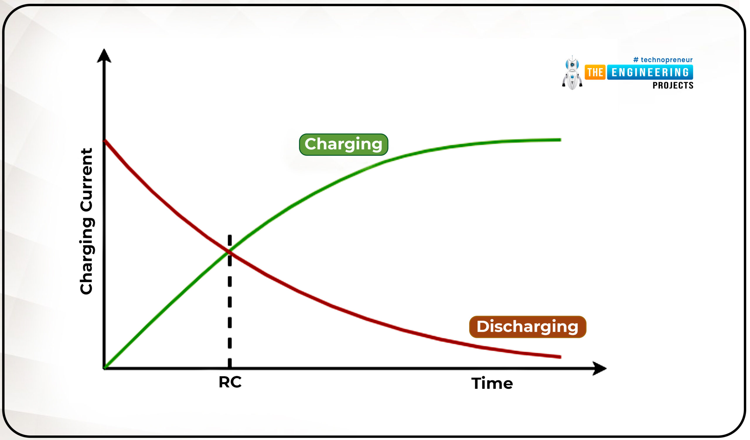