2-to-1 Multiplexer using Logic Gates in Proteus ISIS


Hi Mentees! I welcome you on behalf of The Engineering Projects. In this section of this DLD Logic gates series, we are discussing different applications of logic gates. We have discussed DLD Adders and Subtractors in our previous lectures and now it's time to have a look at DLD Multiplexers.
- What are Multiplexers?
- What are the types of Multiplexers?
- What are the two input Multiplexers?
- How can we simulate the Circuit of 2 to 2 MUX in Proteus ISIS?
- How can we use the 2 to 1 MUX as OR, AND and NOT gates?
What are Multiplexers?
When I heard the word Multiplexer, I thought that as Adder adds numbers, Subtractor subtracts numbers, similarly, the Multiplexer will multiply binary numbers but that's not the case. Multiplexer is defined as:
- A Multiplexer(also called MUX or MPX) is a simple digital electronic circuit, designed using DLD Logic Gates and is used to select a single input from multiple inputs provided to it.
- The input selection is controlled by a separate Input called Select Input(S).
- The selected Input is then forwarded to the Output Terminal.
- In a simple two Input(A1, A2) MUX,
- If S = 0, the output(Y) will be A1
- If S = 1, the output(Y) will be A2.
A Multiplexer is also called Data Selector, Universal Logic Selector, Many-to-one Logic converter and Parallel-to-Serial Convertor because it has the ability to select a single input from multiple inputs.
Let's understand the working principle of Multiplexer in detail:
Multiplexer Working Principle
Let's take the example of the simplest multiplexer i.e. 2-to-1 MUX. It has 2 normal inputs(A1 , A2 ) and 1 Select Input(S) and it generates single Output(Y). Here's the block diagram of a simple 2-to-1 Multiplexer:
As discussed above, the selection of inputs is controlled by the Select Pin(S). So, if S = 0, the output will be A1 and if S = 1, the output will be A2. The relation between Select Input and Output is shown in the below truth table:
| Select Input(S) | Output(Y) |
| 0 | A1 |
| 1 | A2 |
We can understand from the above truth table that we can control maximum 2 inputs from a single Select Input. So, in order to control more than 2 inputs, we need to increase the number of Select Inputs. For example, 2 Select Inputs can control a maximum of 4 Normal Inputs. So, the relation between Select and Normal Inputs can be described by the following formula:
Normal Inputs = 2n
where, n represents the Select Inputs.
So, if we have 5 Select Inputs, we can easily control 25 = 32 Normal Inputs.
Truth Table of 2-to-1 MUX
As we have discussed earlier, the inputs of Multiplexer depends upon a Selector S. therefore, when we design a Truth Table, we include a Selector also in it. While designing a 2-to-1 MUX, we follow the expression given below:Considering the expression above we get the Truth Table of 2-to-1 Multiplexer as follow:Y=D0S' + D1S
| S | D0 | D1 | Y |
| 0 | 0 | 0 | 0 |
| 0 | 0 | 1 | 0 |
| 0 | 1 | 0 | 1 |
| 0 | 1 | 1 | 0 |
| 1 | 0 | 0 | 0 |
| 1 | 0 | 1 | 1 |
| 1 | 1 | 0 | 1 |
| 1 | 1 | 1 | 1 |
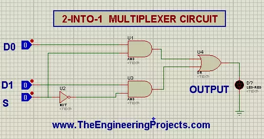
Implementing 2-to-1 Multiplexer in Proteus ISIS
To Design a 2-to-1 Multiplexer, we need the following material:Material Required
- AND Gate
- OR Gate
- NOT Gate
- Logic Toggle
- LED
- Ground Terminal
- Grab the required Material from the Pick Library one after the other by Pressing a "P" button present at the screen.
- Hit and hold the Name of the chosen Logic Gates one by one and arrange them at the screen according to the given image:
- Get Three Logic Toggles and set them just before the Logic Gates.
- Arrange an LED below the OR Gate's output.
- To have a ground Terminal, left click the mouse >Go to Place>Terminal>Ground.
- Join all the Components according to given image below:
- Pop the Play button just at the left corner of the screen and change the input.
- Change the conditions of the System by changing the values of inputs and observe the output.
- AND Gate
- OR Gate
- NOT Gate
Implementing OR Gate through 2-to-1 Multiplexer in Proteus ISIS
The MUX Can easily be used to implement Basic Logic Gate. But before that Recall that what is an OR Gate."An OR Gate is a two input Logical Gate that give the output LOW only when both the outputs are LOW."
Procedure for the conversion of 2-to-1 Multiplexer into OR Gate
- Fix the value of D0 to 1 all the time.
- Change the Value of the S and D2 according to the Truth Table given below and match the result.
| S | D0 | D1 | Y |
| 0 | 0 | 0 | 0 |
| 0 | 0 | 1 | 1 |
| 1 | 0 | 0 | 1 |
| 1 | 0 | 1 | 1 |
Implementing AND Gate through 2-to-1 MUX in Proteus ISIS
Recall the definition of AND Gate:" The AND Gate is the one that consist of two inputs and gives the input HIGH only when both the Inputs are HIGH."Follow the simple steps to use 2-to 1 MUX as an AND Gate.
Steps to use 2-into-1 MUX as AND Gate
- Set the value of D0 as 1.
- Change the values of S and D0 according to table and record your observations.
| S | D0 | D1 | Y |
| 0 | 0 | 0 | 0 |
| 0 | 1 | 0 | 0 |
| 1 | 0 | 0 | 0 |
| 1 | 1 | 0 | 1 |
NOT Gate through 2 to 1 MUX
Prior to start, Let's refresh the definition of NOT Gate in our minds:"The NOT Gate is a 1 input invertor Logic Gate that gives the output 1 when input is zero and vice versa."To use the 2 to 1 MUX as NOT Gate, just follow the steps:
You can check our website for the XNOR, XOR and NOR Gate from 2 to 1 MUX in our Tutorials. Consequently, today we leaned interesting Circuits. We saw what are 2 to 1 Multiplexers. We made a circuit of the 2 to 1 MUX and from the circuit, we found how can we use them as OR, AND and NOT logic Gates along with the truth tables of each.
- Set the D0 input as 0.
- Set D1 as 1.
- Change the value of S as 1 and zero one after the other.
- You will Observe that when S=1 the output is 0 and vice versa.
- Hence this is our required result.