


NOR as Universal Gate in Proteus ISIS


Hi Mentees! I hope you all are having a Productive Day. In our previous lecture, we discussed the DLD Basic Logic Gates and simulated them in Proteus. Today, we are going to use these standard logic gates and will design another logic gate named NOR Gate and will also simulate it in Proteus.

In this tutorial, we'll learn the following concepts:
- What is a NOR Gate?
- Why NOR is called Universal Gate?
- How to derive other Gates through NOR Gate?
- Advantages of NOR Gate.
Let's begin the exploration:
What is a NOR Gate?
- "NOR gate is designed by inverting the output of an OR Gate, so it gives a HIGH output, only when all the inputs are LOW."
- In simple words, a NOR Gate has an OR Gate followed by the NOT Gate, as shown in the below figure:

- The Graphical Symbol of a NOR Gate is the same as that of the OR gate but we place a small bubble at the start of the output, which represents the NOT gate, shown in the above figure.
- Assume that A and B are the inputs of a NOR Gate, Output Y is denoted by a plus sign between inputs with a collective bar or complement sign on the whole statement as:
Y = (A + B)'
Truth Table and Timing diagram of NOR Gate
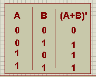
A Truth Table is a tabular representation of a logic gate having all the possible scenarios. The Truth table of the NOR Gate for 2 inputs is as follows:
| A | B | (A+B)’ |
| 0 | 0 | 1 |
| 0 | 1 | 0 |
| 1 | 0 | 0 |
| 1 | 1 | 0 |
- The timing diagram of the NOR Gate is as follows:

What is a Universal Gate?
- A logic gate is called Universal Gate, if we could design all the other logic gates using it.
- There are two Universal Gates available, named:
- NOR Gate.
- NAND Gate. (we will cover in the next chapter)
We have studied basic DLD logic gates i.e. AND, OR and NOT in our previous lecture. We can design all these gates with the Universal Gate. Let's have a look:
NOR as Universal Gate in Proteus ISIS
In this section, we are going to design the 3 basic logic gates(AND, OR and NOT) using NOR gate. While Designing the circuits, we need the following components:
Material Required
- NOR Gate
- Logic Toggle
- LED
- Ground Terminal
- Connecting Wires
NOT Gate
- In order to design a NOT Gate with NOR Gate, we simply need to combine the inputs.
- Mathematically,
(A.A)'=A'
- The Proteus simulation of NOR gate acting as a NOT gate, is shown in the below figure:

- I have attached an LED at the output to analyze the working.
- Hence, we found the Truth Table as:

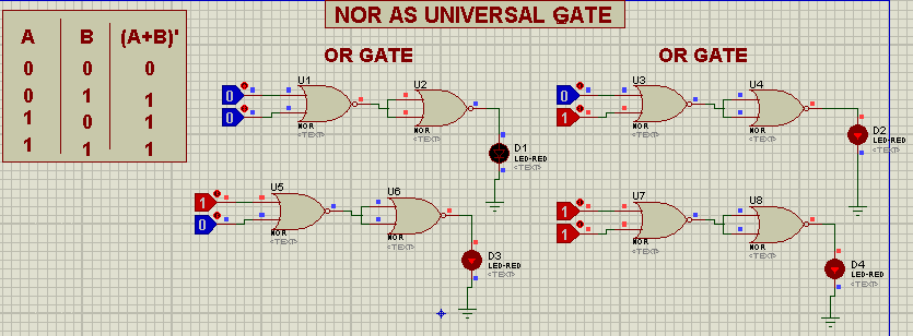
OR Gate
During the formation of OR Gate through NOR Gate, we have to keep in mind the following statement:"The output of NORed inputs is also the ORed input."We denote this Statement as:
(A.B)'=A+B
- Take two NOR Gates.
- Connect the second NOR Gate's inputs with each other.
- Join the output of first one with the output of the other.
- Join grounded LED and Logic Probes for input and output respectively.
- Pop the play button.


AND Gate
The core statement of the formation of AND Gate through NOR is given next:"The NORed output of Complements of the input is AND Gate."Mathematically,
(A'+B')'=AB
- Get the two NOR Gates from Pick Library.
- Fix them vertically at the working sheet.
- Connect the input of each of them with themselves.
- Join Logic Toggle with each of it.
- Take another NOR Gate from the pick Library.
- Connect the output of 1st two with the input of the third.
- Get the Grounded LED and fix it at the remaining output.

- Press the Play sign of the Proteus ISIS.
- Design the Truth Table by applying the required inputs.
Advantages
- It occupies little space.
- It is less expensive.
- we can use it in the place of four Gates.
- It is less complex.


