XOR Gate with Truth Table in Proteus


Hey pals, we hope you are doing well. In our previous lecture, we discussed the basic DLD Basic Logic Gates and simulated in Proteus. Today, we are going to discuss another logic gate called Exclusive OR Gate(XOR Gate). We will also design the XOR Gate in Proteus using the basic logic gates(i.e. AND, OR and NOT), discussed in the previous lecture.
In today's tutorial, we are going to focus on:
- What are Exclusive OR Gates
- Experimental Proof in Proteus ISIS.
- How Truth Table of Exclusive OR Gate is designed.
- How is its Timing Diagram?
- Circuit of Exclusive OR Gate in Proteus Simulation
- Applications of Exclusive OR Gates
Exclusive OR Gate(XOR Gate)
- In the Exclusive OR Gate(XOR Gate), the output will be HIGH(1), only if the odd no. of inputs is HIGH(1) and at least one of the inputs is LOW. (it's a bit complex, will understand it in the next section)
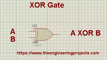
- The XOR Gate is denoted by a plus sign with a circle around it between the inputs i.e. .
- XOR gate is designed by combining standard logic gates(i.e. AND, OR and NOT), but because of its extensive use in arithmetic operations and error detection, it's considered a standard logic gate.
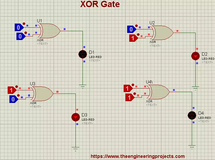
- The Truth Table of XOR Gate is given below:
| A | B | |
| 0 | 0 | 0 |
| 0 | 1 | 1 |
| 1 | 0 | 1 |
| 1 | 1 | 0 |
- The XOR Gate symbol along with its representation and truth table is shown in the below figure:
Working Principle of XOR Gate
Its definition has two conditions in it:
- Odd no. of Inputs should be HIGH
- At least one of the inputs should be LOW
We have seen in the 2-Input XOR truth table, the output is HIGH in the 2nd and 3rd Rows, because these rows are fulfills both conditions i.e., we have an odd no of HIGH inputs(1 input is HIGH) and at least 1 LOW input(1 Input is LOW). While, in the 1st and 4th rows, both conditions are unfulfilled, thus getting LOW at the output.
Now, let's have a look at the truth table of the 3-input XOR Gate:
Image
Now it will get more clear, as you can see in the 4th row, we have 1 HIGH Input and 2 LOW Inputs, thus both conditions are fulfilled and we are getting HIGH at the OUTPUT. But in the 7th row, 2 Inputs are HIGH and 1 is LOW, although the 2nd condition is fulfilled i.e. we have at least 1 LOW input but the first condition is unfulfilled i.e. we have even no of HIGH Inputs. That's why we are getting LOW at the output. I hope now it gets clear.
Mathematical Representation of XOR
Now let's understand the output of the XOR gate mathematically. XOR gate is used in arithmetic calculations because it adds the inputs and gets the carry.
Here's the mathematical calculation of XOR truth table:
0+0=0
0+1=1
1+0=1
1+1=0 (Carry)
Here's the Proteus demonstration of the XOR truth table:
Design XOR Gate with Standard Logic Gates
Now, we are going to design an XOR gate using the basic logic gates i.e. AND, OR and NOT. The formula for XOR Gate is as follows:
Y = A.(B)' + (A)'.B
As you can see in the above equation, we can get an XOR output(Y) by applying 3 logic gates i.e. AND, OR and NOT, on the inputs(A and B).
Let's verify this equation by putting values from the XOR truth table:
For 1st Row:
=0.(0)'+(0)'.0
=0.1+1.0
=0+0
=0
For 2nd Row:
Now, A=0, B=1:
=0.(1)'+(0)'.1
=0.0+1.1
=0+1
=1
For 3rd Row:
Consider A=1, B=0:
=1.(0)'+(1)'.0
=0.1+0.0
=1+0
=1
For 4th Row:
At last, check the expression when A=1, B=1:
=1.(1)'+(1)'.1
=1.0+0.1
=0+0
=0
So, now let's design this equation for the XOR Gate in the Proteus software. Let's get started:
Proteus Simulation of XOR Gate
As we have seen in the previous section, we need to implement this equation in the Proteus software:
Y = A.(B)' + (A)'.B
So, open your Proteus software and get these components from the Proteus library:
Material Required:
- AND Gate
- OR Gate
- NOT Gate
- Logic Toggle
- LED
Circuit Diagram of XOR Gate:
Here's the circuit diagram of the XOR Gate in Proteus using the standard logic gates i.e. AND, OR and NOT:
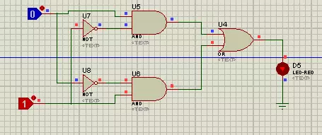
- As you can see in the above figure, the upper AND gate is implementing the first part of the equation i.e. A.(B)' and the second AND gate is implementing the second part i.e. (A)'.B
- NOT Gate in inversing the inputs, placed at the inputs of AND Gates.
- Finally, we placed an OR gate to add the outputs from both AND gates so that we could complete the equation i.e. A.(B)' + (A)'.B
- Finally, we placed an LED at the output.
Applications of XOR Gate
XOR Gate is used in many circuits as:- We use XOR Gate in Half Adder.
- It is used in the circuit of Controlled inverters.
- XOR is also used in comparators.
- Subtractor is the application of XOR Gate.
- The parity checker is made through XOR Gate.
- XOR is used in the Arithmetic Logic Circuits.
- Circuit of Binary to Grey and vice versa.