4-Bit Full Adder using Logic Gates in Proteus


Hi Learners! I hope you are having a productive Day. Welcome from the Team of The Engineering Projects. The digital logic circuit that we are learning today is 4-Bit Full Adder. In our previous tutorial, we designed 2-Bit Full Adder using Logic Gates in Proteus software. Today, we are going to design & simulate 4-Bit Full Adder using Logic Gates in Proteus.
We will discuss the following topics in today's lecture:
- What is Adder?
- What is Full Adder?
- Working Principle of 4-bit Full Adder.
- Simulation of four-bit full Adder in Proteus ISIS.
What is Adder?
Let's recall the Adder Definition from our previous lectures:
- Adders are Digital Logical Circuits, specially designed to add two or more binary numbers or bits.
In the world of electronics, adders are used to add bits. The computer system depends upon the flow of bits and the computation of bits. Adders take the input in the form of bits and perform the addition, according to the type of Adder used. Basically, we divide the adders into two types:
- Half Adder.
- Full Adder.
We have discussed both Half Adder & Full Adder in detail in our previous lectures. Yet we have to recall the full adder's introduction:
What is Full Adder?
"Full Adders are the Digital Logic Circuits used to add three input bits and generate two outputs i.e. the Sum and the resultant Carry."
We further classify the Full Adder into two main types:
- 2-bit Full Adder.
- 4-bit Full Adder.
4-bit Full Adder
As the name implies, a four-bit full adder is used to add four sets of input bits. The definition of a 4-bit Full adder is as follows:
- "A 4-bit Full Adder is designed to generate a 4-bit Sum and is designed by combining four 2-bit Full Adders and as a result shows the Four bits output along with the Carry Bit."
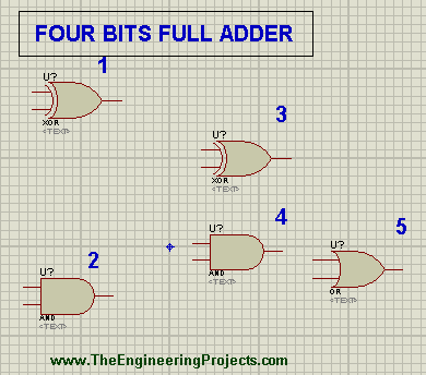
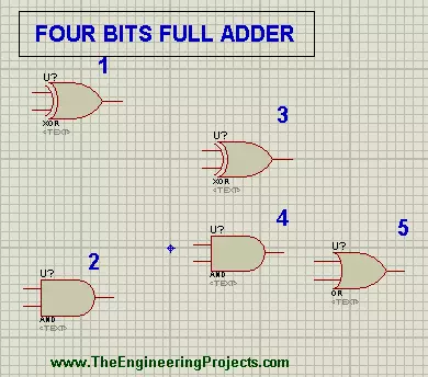
The Circuit of the Four-bit Full Adder consists of the XOR Gate, AND Gate and OR Gate. Let's have a quick recap of these Gates.
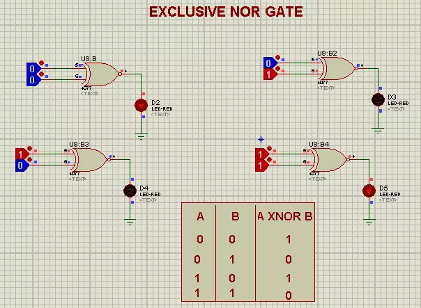
XOR Gate
A XOR Gate, is a two input Logical Circuit that give the output HIGH only when the inputs have the values alternating of each other. Or else, it is LOW.
AND Gate
AND Gate is the a logical Circuit that gives the Output HIGH only when its both inputs are HIGH, otherwise the output is LOW.
OR Gate
The OR Gate is a logical Circuit with the working such that when on of the Input is HIGH, the value of the Output is also HIGH.
Working Principle of 4-bit Full Adder
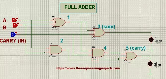
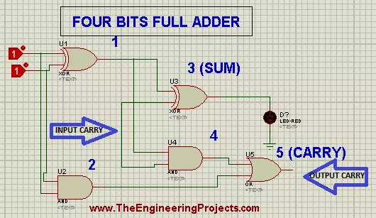
The Four Bit Full Adder works in an interesting manner. The XOR Gates are responsible for the addition of input bits. In order to get the full addition circuit we attach two AND gates with the circuit in such a way that the result of addition connects the OR Gate and we get the carry.
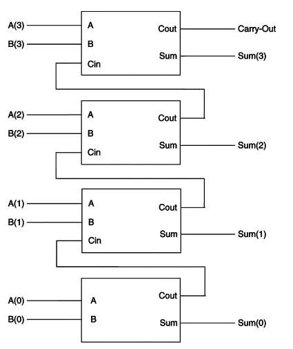
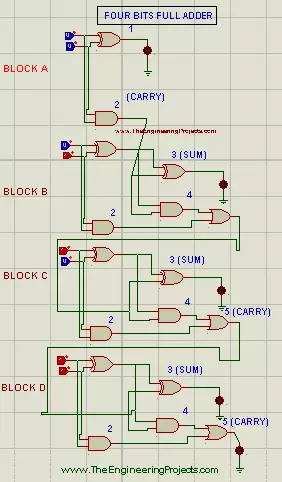
In the designing of circuit, we simply make a small circuit of AND Gate and XOR Gate. Then we design a Circuit of two bits Full Adder. The cynosure of the circuit is, we'll copy the block and arrange four blocks in a way that the output carry of the block becomes the input carry of the next. This cycle will continue and at the fourth block we get the resultant carry of whole calculation. we can input only one carry of our will at the Block A.Practical performance of 4-Bit Full Adder
If you wish to stimulate the Four bits full adder in Proteus then follow the simple steps given below. We'll make our circuit according to the Functional Diagram given before.- Begin Your Proteus Software.
- Get the required material.
Required Devices
- XOR Gate
- AND Gate
- OR Gate
- Logic Toggle
- LED
- Ground Terminal
- Push the "P" button presented at left area of the screen.
- Select first four elements from the Library by mere writing there names one after the other.
- Get a XOR Gate and one AND Gate.
- Connect the Logic Toggles with each input of XOR Gate.
- Connect an LED with the end of the XOR Gate.
- Go to Terminal Mode and get the ground terminal to attach the Ground Terminal with LED.
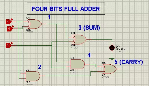
- Drag and drop two XOR Gates, two AND Gates and one OR Gate and arrange them at the working area one after the other according to the image given below:
- Attach Logic Toggle with each input of switch 1.
- Get the LED and join it with the output of switch 3.
- Click the left button of mouse> go to Terminals> Ground Terminal.
- Place the ground Terminal just below the LED.
- Join all the components according to the images given below;

- Select the whole block left click>drag and drop the required area. It will create a doted square around the circuit.
- Right Click> copy block.
- Right click the mouse and paste the block with the same procedure.
- Repeat the Pasting Process one time more and paste the circuit copy just one below the other.
- Connect the each output carry switch with the input of the next.
- Grab the Logic Toggle from the Pick Library and join it with the input carry wire of the first block.
- Change the input values by the mean of Logic Toggles and check the working.
Working Example of 4-bit Full Adder in Proteus
You can test the circuit with an example. Question: We have two numbers 1100 and 1010. Find the resultant through four bits Full Adder. Answer: Let A=1100 B=1010Logic about For bit Full Adder
The 1st Logic Toggle of each XOR 1 switch is called A bit. The 2nd Logic Toggle of each XOR 1 represents the B bit. Turning of LED means the HIGH (1) and vise versa. We start to input from down to up and the output as well. Hence start the observation from block D to A. For the Question, the circuit should be set as: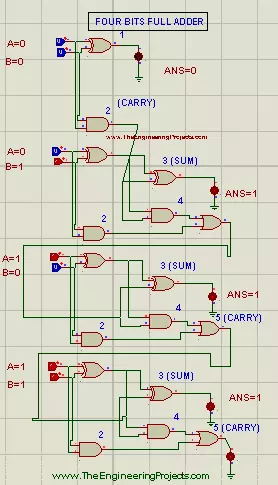
| A | 1 | 1 | 0 | 0 |
| B | 1 | 0 | 1 | 0 |
| Result | (1 carry)0 | 1 | 1 | 0 |