2-Bit Full Adder using Logic Gates in Proteus


Hello Learners! I hope you are doing great. Welcome to The Engineering Projects. In our previous lecture, we discussed How to design Half Adder with Universal Gates. In today's tutorial, we are going to design Full Adder with Logical Gates.
In today's tutorial, we will learn the complete information about:
- What is Adder?
- What is Full Adder?
- How is the Truth Table of Full Adder?
- How can we design Full Adder in Proteus ISIS?
- What are the uses of Full Adder?
What is Adder?
Recalling from our previous lectures:
- The Adders are simple Logical Circuits that take the bits in as the input, sum the bits together and generate the sum and the carry at the output.
- Adders are present in computer architecture, mainly to control the addressing of the Arithmetic Logic Unit(ALU).
We classify the Adders into two types:
- Half Adder.
- Full Adder.
We have discussed half Adder in detail in our previous two lectures. Today we'll stress the Full Adder:
What is Full Adder?
There are two types of Full Adders:
- 2-bit Full Adder.
- 4-Bit Full Adder. (We will discuss in the next lecture)
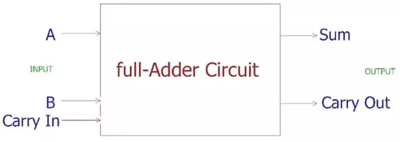
We define the Full Adder as:
- A Full Adders is a simple Logical Circuit, that takes 3 inputs(1-bit each) and generates two outputs i.e. the Sum(1-bit) and the Carry(1-Bit).
- A Full Adder takes 2 inputs A and B, while the third input is actually the Carry Input.
- We have seen in the Half Adder that we took 2 inputs and calculated the Sum and the Carry but we have no way of adding that Carry back into the Sum.
- This problem is solved by the Full Adder, which takes the Carry and adds it in the Sum to get a final Sum.
- That's why, we can use multiple Full Adders in series to add any amount of Bits.
- For example, we can serially attach 8 Full Adders to add 8 Bits of data(1-byte).
The Full Adder plays an important role in computer hardware calculations i.e. ALU control, register addressing etc. Here's a simple 2-Bit Full Adder Circuit using Logic Gates:
Truth Table of 2-bit Full Adder
As discussed above, there are three inputs and two outputs present in Full Adder. Therefore, the Truth Table of Full Adder will have 5 columns in total:
The input combinations of the Truth Tables are followed through the formula:
Numbers of Combinations= 2^n
where n is the number of inputs. In our case,n=3
hence,Numbers of Combinations=8
We start the truth table from zero bit. The right most input has the alternative inputs after each combination. The middle contains the alternative bits after two combinations. By the same token the left most changes the input bit after four combinations.
The Truth Table of Full Adder looks like this:
| A | B | Cin | Sum |
C0 |
| 0 | 0 | 0 | 0 | 0 |
| 0 | 0 | 1 | 1 | 0 |
| 0 | 1 | 0 | 1 | 0 |
| 0 | 1 | 1 | 0 | 1 |
| 1 | 0 | 0 | 1 | 0 |
| 1 | 0 | 1 | 0 | 1 |
| 1 | 1 | 0 | 0 | 1 |
| 1 | 1 | 1 | 1 | 1 |
| Carry+A+B | Sum | Carry out | ||
Simulation of Full Adder in Proteus ISIS
To design a Full Adder in Proteus, get these components from the library:
Components Required
- XOR Gate
- AND Gate
- OR Gate
- Logic Toggle
- LED
- Ground Terminal
- Get the first five components from the Pick Library through the "P" button.
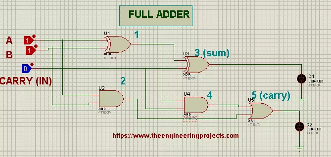
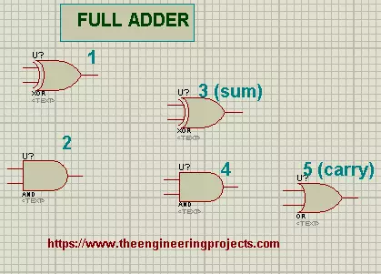
- As shown in the below figure, I have placed the 5 Logic Gates in our Proteus workspace.
- We have 2 XOR Gates at the top, after that we have 2 AND Gates and finally an OR Gate at the end.
- The circuit should look like this:
- Now, connect two Logic Toggles with the inputs of Logic Gate 1.
- Connect one Logic Toggle with the 2nd input of Logic Gate 3.
- Attach the LED with the Gate 3 output and ground the LED with Ground Terminal present in "Terminal Mode" on the leftmost bar of the screen.
- Repeat the above step for Logic Gate 5.
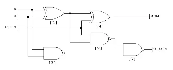
- Connect all the Logic Gates according to the diagram given next:

- Change the Input bits and record your own truth table.
- To understand the working better, we'll design a Truth Table that describes the output of each Logic Gate.
| Input | Output | ||||||
| A | B | Cin | Gate1 |
Gate2 | Gate4 | Gate3(Sum) | Gate5 C0 |
| 0 | 0 | 0 | 0 | 0 | 0 | 0 | 0 |
| 0 | 0 | 1 | 1 | 0 | 0 | 1 | 0 |
| 0 | 1 | 0 | 1 | 0 | 0 | 1 | 0 |
| 0 | 1 | 1 | 0 | 1 | 0 | 0 | 1 |
| 1 | 0 | 0 | 0 | 0 | 0 | 1 | 0 |
| 1 | 0 | 1 | 1 | 0 | 1 | 0 | 1 |
| 1 | 1 | 0 | 1 | 0 | 1 | 0 | 1 |
| 1 | 1 | 1 | 0 | 1 | 0 | 1 | 1 |
| Carry+A+B | Sum | Carry out | |||||
Truss, we got a Full Adder circuit through which we can make the calculations.
Uses of Full Adder
- Full adders are paramount for the on-chip Libraries.
- They are used in computers for table indices.
- They are used by the processor to add the addresses.
- Full adders are used in Arithmetic Logic Unit.
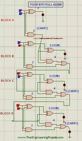
- Full Adders are used in the Computer for the series calculations. For this purpose, they may be connected in the way given next in the image. Observe it from bottom to top.[TEPImg6]
- It can be designed so, that we can input eight bits together that collectively work as a byte.