Hello friends, I hope you all are doing great. Today, I am going to share the new Toggle Switch Library for Proteus. Few parts feel as satisfying as a toggle switch. You push the little metal lever, it snaps across with a firm click, and something happens. You will find it on guitar amplifiers, on the dashboards of old cars, on lab power supplies and on the overhead panel of an aircraft. It tells everyone exactly what state a machine is in, from across the room.
Toggle Switch Library for Proteus
Latest version: V1.0 (November 2026, this tutorial)
Other component libraries: C945 Transistor · PC817 Optocoupler · Relay Module · Resistor · 5 mm LED · Designer Colour LED · Push Button · Active Buzzer · Electrolytic Capacitor · Ceramic Capacitor · Tantalum Capacitor · Film Capacitor · 1N4007 Diode · Zener Diode · Schottky Diode · Supercapacitor · Photodiode · RGB LED · Bridge Rectifier · Flashing LED · Bi-Colour LED · SMD LED · Slide Switch · Rocker Switch · Micro Limit Switch · Emergency Stop Switch · SMD Resistor · Power Resistor · Resistor Network · Potentiometer · Trimmer Potentiometer · Slide Potentiometer · NTC Thermistor · DIP Switch · Fuse · Passive Buzzer · Mini Speaker · 7-Segment Display · LED Bar Graph · IR / UV LED · Small Transistors · TIP122 Darlington · N-MOSFET · P-MOSFET · PC817 Optocoupler · Filament Bulb · Power LED · Voltage Regulator · SCR and TRIAC · Inductor · Toroid Inductor · Crystal
Helping Tools
- Serial Monitor Advance: a serial terminal window for the UART of your board
- Serial Monitor Expert: the serial monitor with extra debugging tools
- LCD Library for Proteus V3.0: 16x2, 20x4 and I2C LCDs to show your readings
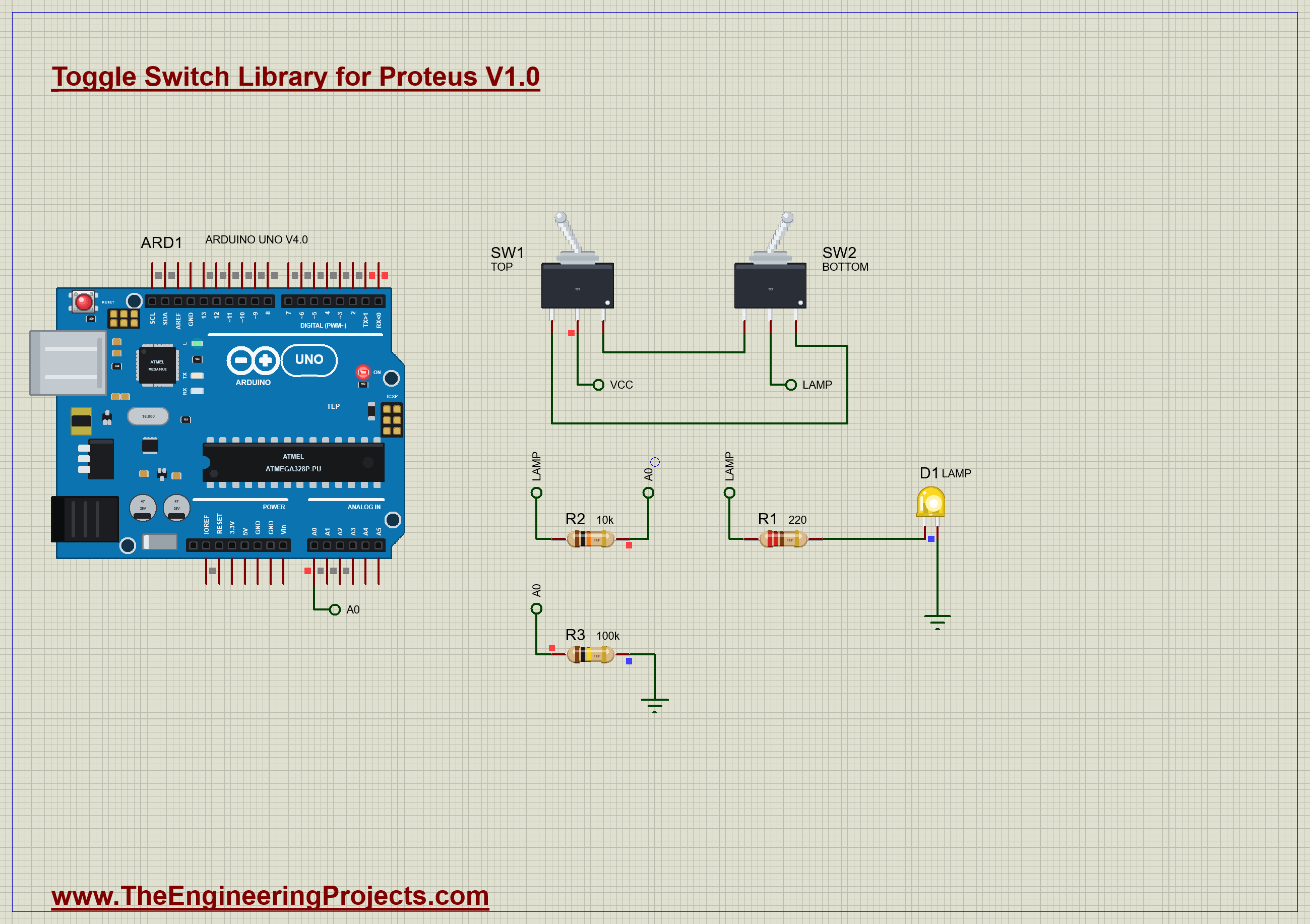
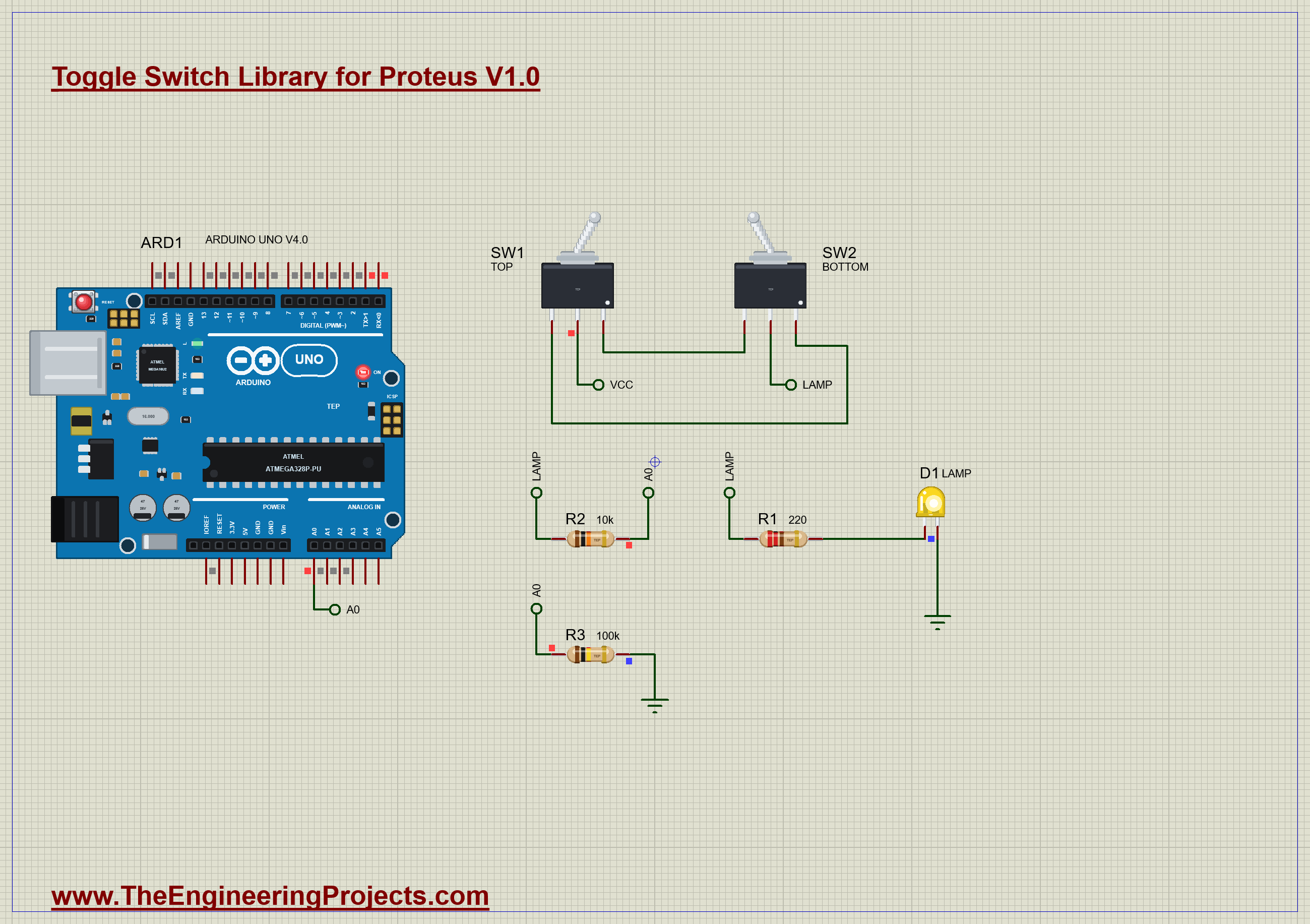
Our part is the well-known MTS-102, at true scale, with its black body, threaded neck, nut, chrome bat handle and three lugs. Click it at Run and the handle really flips, and the sheet keeps that position after you stop the simulation. Inside it behaves like the real thing, with a small contact resistance and true contact bounce. For the demo we have built the classic two-way lamp, the circuit on your own staircase, where two switches work one light and neither is in charge.
NOTICE: Our team has put a lot of effort into these small parts: the bodies, the animation and the pop-ups are all our own design, and you get them free. Your feedback is the fuel that keeps us going, so please tell us what you think in the comments below or in the Toggle Switch board of our forum. And if our free libraries help you, you can buy us a coffee. So, let's get started with the Toggle Switch Library for Proteus:
What is a Toggle Switch?
A toggle switch is a mechanical switch worked by a short lever that you push from one side to the other. The lever pivots inside the neck of the switch, and its lower end moves a contact inside the body. A spring holds the lever firmly at either end of its travel, so it never sits halfway. That is called a maintained switch: it stays wherever you leave it, unlike a push button, which springs back as soon as you let go.
The MTS-102 is an SPDT part, which stands for single pole, double throw. The middle lug is the common, and it joins one of the two outer lugs. We looked at those words closely in our Slide Switch Library for Proteus, and the same ideas apply here. What changes is the size of the part, the current it can carry, and the way it fixes to a panel.
| Feature | The real part | In the library |
|---|---|---|
| Body | MTS-102, about 13 x 8 mm | 546 x 340 thou, true scale |
| Legs | three solder lugs | the same: 1, C and 3 |
| Rating | about 6 A at 125 V AC, 3 A at 250 V AC | the Check page warns over 3 A |
| Contact | a few tens of milliohms | 0.02 ohm, a property |
| Action | snaps over, and stays | a click flips the handle |
Why Does the Handle Lean the Other Way?
Here is a detail that surprises nearly everyone the first time. The handle of a toggle switch leans away from the contact it makes. Push the handle to the right, and the common lug joins the left lug. The reason is simple once you see it: the lever is a seesaw with its pivot in the neck. When the top goes right, the bottom goes left, and the bottom is what carries the moving contact. Our part behaves the same way, so that what you learn on the sheet is true on the bench.
How the Snap Action Works
The firm click is not just there to feel nice. Inside the body, a small spring pushes a plunger against a rocking contact. As you move the handle, the spring is squeezed. Once the handle passes the middle, the spring pushes the contact across at speed, whatever your hand is doing. This matters because a contact that opens slowly lets an arc burn across the gap, and an arc wears the metal away. A fast snap gets the contact clear quickly and makes the switch last far longer.
The MTS Family
The name of these small switches is a short code, and it is worth learning, because the shops list them all side by side. The first digit counts the poles. The last digit tells you about the positions, and a middle OFF position is the one to look out for.
| Part | Type | Positions | Typical use |
|---|---|---|---|
| MTS-101 | SPST | ON and OFF | a plain power switch |
| MTS-102 | SPDT | ON and ON | pick between two things |
| MTS-103 | SPDT | ON, OFF and ON | forward, stop and reverse |
| MTS-202 | DPDT | ON and ON | two circuits at once, or reversing a motor |
The Rating Printed on the Side
Look at the body of a real toggle and you will usually see two lines, such as 6 A at 125 V AC and 3 A at 250 V AC. Why would the current fall when the voltage rises? A higher voltage drives a stronger arc as the contact opens, so the switch must carry less current to break it safely. Direct current is harder still. An alternating current passes through zero a hundred times a second or more, and that helps the arc to go out. A direct current never does, so an arc on a DC circuit can keep burning. That is why a switch rated for several amps on AC may be rated far lower on DC, especially for a motor or a solenoid, whose coil tries to keep the current flowing.
The model does not know about the voltage. It watches the current through the closed contact and compares it with 3 A, and the Check page warns if you go over. Treat that as a reminder to read the data sheet of your own part, not as a promise.
The Two-Way Lamp
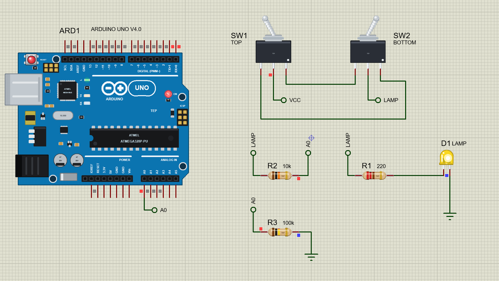
This circuit is the real reason this demo exists. A lamp on a staircase needs a switch at the top and another at the bottom, and either one must be able to change the light, whatever the other one is doing. An ordinary on and off switch cannot do that, because if one of them is open, the other one has no effect. The answer is two SPDT switches and two wires between them, called the travellers.
The supply goes to the common leg of the first switch, which sends it down one traveller or the other. The lamp hangs on the common leg of the second switch, which listens to one traveller or the other. If the two switches pick the same traveller, the circuit is complete and the lamp lights. If they pick different ones, the supply is waiting on one wire and the lamp is listening to the other, so nothing happens. Now flip either switch. Whichever one you touch, the two of them go from agreeing to disagreeing, or the other way round, so the lamp must change. There is no logic chip here and no program, just two levers and two wires.
| SW1 joins | SW2 joins | Do they meet? | The lamp |
|---|---|---|---|
| leg 1 | leg 1 | no, different wires | off |
| leg 3 | leg 1 | yes | on |
| leg 3 | leg 3 | no, different wires | off |
| leg 1 | leg 3 | yes | on |
Notice that in our demo the travellers run from leg 3 to leg 1, and from leg 1 to leg 3. They could equally run from leg 1 to leg 1. The circuit works either way, and only the positions that mean "on" change. We chose this way simply because no wires have to cross on the sheet.
Three Switches or More
What if a long corridor needs three switches? You keep the two SPDT switches at the ends, and put a DPDT switch in the middle, wired to swap the two travellers over. Each time you flip it, the wire that used to reach the far end now reaches the other side, so the lamp changes again. Add as many of these as you like. Electricians call that an intermediate switch in some countries, and a four-way switch in others, which is confusing, but it is the same idea.
Reading a Toggle with an Arduino
A toggle switch is just as happy as an input to a sketch. The neat way uses all three lugs: join one outer lug to GND, the other to +5V and the common to the pin. The pin then always sits on a clean LOW or HIGH, with no resistor. If you only have an SPST switch, use the common lug and one outer lug, and turn on the pin's pull-up with INPUT_PULLUP. Either way, remember that the contact bounces as it lands, so give the reading a small debounce in the sketch.
Mounting One on a Panel
Unlike a slide switch, which sits on a board, a toggle is made to mount on a panel. You drill a 6 mm hole, push the threaded neck through from behind, and tighten the nut on the front. Many switches come with a lock washer, and some have a tab that stops the body from turning. Do not use pliers on the nut, since a slip will scratch the panel. The three lugs stay behind the panel, and you solder the wires to them. Slide a piece of heat-shrink tube over each joint, especially if the voltage is anything more than a few volts.
Think also about which way up the switch goes. In many countries a switch is up for on. In others, down is on. In a piece of equipment, the important thing is to be consistent, so that a whole row of switches pointing the same way means the same thing. Pilots rely on exactly this. A glance along a panel shows at once if one lever is out of line with its neighbours.
Guards and Locks
Because a toggle is so easy to flip, an important one is often protected. A hinged red cover, sometimes called a missile switch cover, has to be lifted before the lever can be reached. Some levers have a collar that must be pulled out before they can move. Both exist for the same reason: the switch should need a deliberate act. On a piece of test equipment, or anywhere a slip of the hand would do harm, that small extra step is worth having.
Features of the Toggle Switch Library for Proteus
- The real look, at true scale: the black body, threaded neck, nut, chrome bat handle and three legs, with our small TEP signature.
- Click to flip: a click on the switch throws the handle across, at Run.
- It stays where you leave it: the position stays after Stop, and you can pick it while stopped too.
- The true lean: the handle leans away from the leg it joins, as a real toggle does.
- True contact behaviour: a small resistance closed, break before make, and real contact bounce.
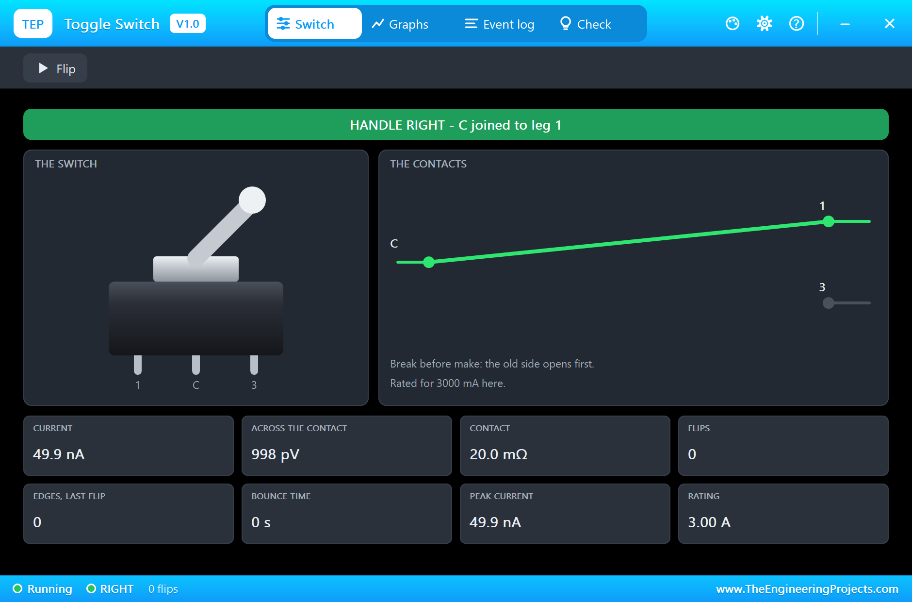
- A live path: the pop-up draws the contacts, and shows which way the common leg is joined.
- A true analog part: it works with any circuit, not only with logic.
- A pop-up for every part: click the small dot at Run for the contacts, eight live values, graphs, an event log and a check page.
- A complete package: about 1.8 MB with the library, our Arduino UNO V4.0, the demo's resistors and LED and the demo, without the source code of the models.
The Toggle Switch in Proteus
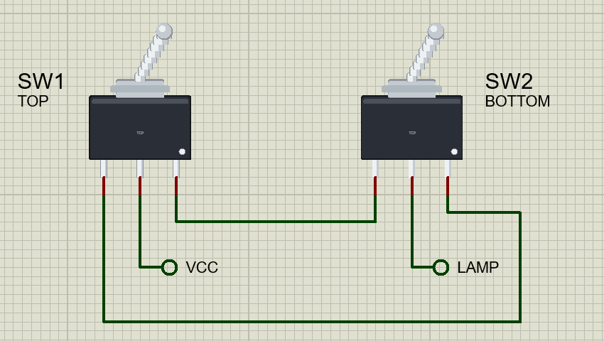
The device is SWITCHTOGGLETEP in TEPTOGGLE.LIB, under Switches and Relays, Switches, with the prefix SW and the model TEPTOGGLE.DLL. Search SWITCHTOGGLE in Pick Devices. The pins are 1, C and 3, with C in the middle.
Click It, or Open It
A click anywhere on the body or handle flips the switch while the simulation runs. A click on the small round dot in the corner of the body opens the pop-up instead, and leaves the switch alone.
The Properties
| Property | What it does |
|---|---|
| Contact resistance, ohm | the closed contact, 0.02 ohm by default |
| Contact bounce, ms | how long it chatters, 3 ms by default; 0 is a perfect contact |
| Position while stopped | Handle right or Handle left: where it starts |
Download Toggle Switch Library for Proteus
Click the button below to download Toggle-Switch-Library-for-Proteus-v1.0.zip (about 1.8 MB, without the source code of the models):
Toggle Switch Library for Proteus V1.0- README.txt: installation, the demo, the properties, troubleshooting and the limits.
- Proteus Library Files:
TEPTOGGLE.LIB,TEPRESISTOR.LIB,TEPLED5MM.LIBand ourArduinoV4TEP.LIB. - Proteus Model Files:
TEPTOGGLE.DLL,TEPRESISTOR.DLL,TEPLED5MM.DLLandTEPARDUINO.DLL. - Arduino Code: the demo sketch.
- Proteus Simulation: the demo project, its HEX file and copies of the DLLs.
No Proteus yet? Read How to Download and Install Proteus 7 and 8. New to libraries? Follow How to Install a New Library in Proteus.
How to Install Toggle Switch Library for Proteus
- Close Proteus and extract the whole zip file, for example to your Desktop.
- Copy the files from Proteus Library Files into the LIBRARY folder of Proteus.
- Copy the files from Proteus Model Files into the MODELS folder.
- Delete
TEPTOGGLE.IDXfrom the LIBRARY folder if it is there. - Start Proteus, press P and search for SWITCHTOGGLE.
Demo: The Two-Way Lamp
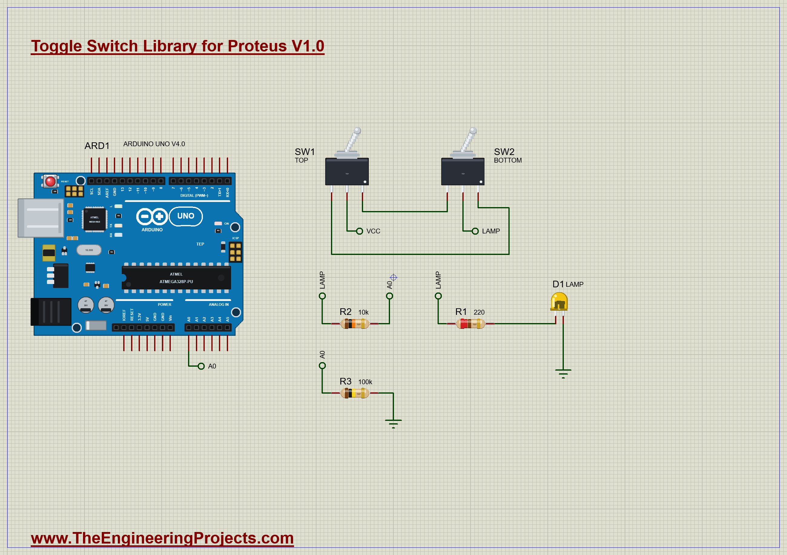
The demo is the staircase lamp from above. SW1 is the switch at the top, SW2 the switch at the bottom, and the yellow LED D1 is the lamp. Open Toggle-Switch-Two-Way-Lamp-ArduinoUnoV4.pdsprj. It runs on our Arduino UNO Library for Proteus V4.0, with its built-in monitor, the same window as our TEP Serial Monitor Advance for Proteus. The resistors are from our Resistor Library for Proteus and the lamp from our 5 mm LED Library for Proteus.
The Arduino is only supplying 5 V and keeping score here. It has no say in whether the lamp is on. Take the board away, give the circuit any 5 V supply, and the lamp will work just the same. That is the whole charm of this circuit.
| Part | Connection | Job |
|---|---|---|
| SW1 | C to +5V | sends the supply down one traveller |
| SW2 | C to the LAMP wire | takes the lamp's power from one traveller |
| Travellers | SW1 leg 3 to SW2 leg 1, SW1 leg 1 to SW2 leg 3 | the two wires between the switches |
| D1 and R1 | LAMP, through 220 ohm, to GND | the lamp |
| R2 and R3 | LAMP to A0 through 10k, and 100k to GND | lets the sketch watch the lamp |
Watching the Lamp
The two resistors let the sketch see the LAMP wire safely. When the lamp is on, the wire sits at 5 V, and A0 reads a high value. When the switches disagree, the wire is joined to nothing at all, and R3 pulls A0 down to zero. Without R3, the pin would float and read nonsense. The sketch treats anything above half scale as on.
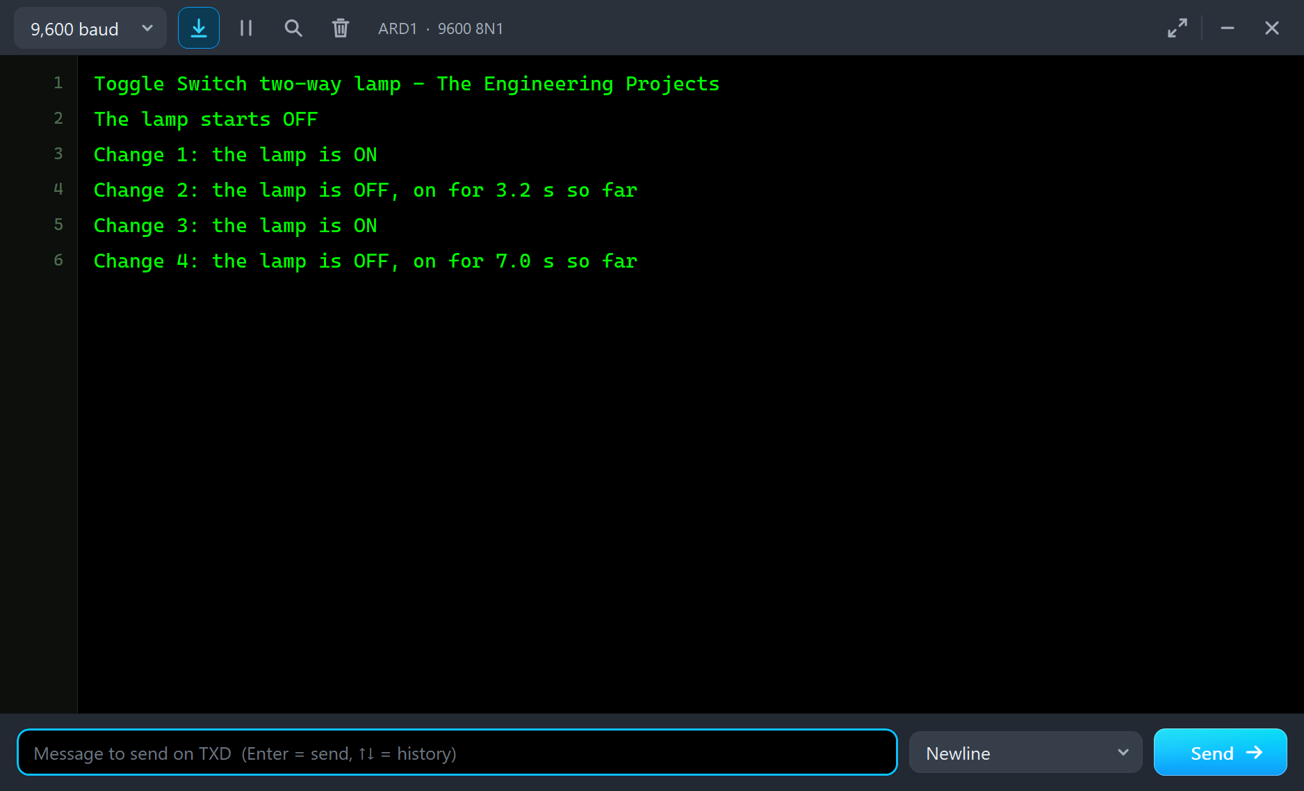
It debounces that reading in the usual way. It notes when the reading changes, and it only believes a new value once it has held for 20 ms. Then it counts the change:
  if (millis() - changedAt >= DEBOUNCE_MS && reading != lamp) {
    lamp = reading;
    changes++;
The sketch also adds up how long the lamp has been on, which is something a real switch can never tell you. It remembers the moment the lamp came on, and adds the difference when it goes off:
    if (lamp) lampOnAt = millis();
    else onTotal += millis() - lampOnAt;
Run the Demo
Press Run. Both handles are to the right, so SW1 joins leg 1 and SW2 joins leg 1. In our wiring those are different wires, so the lamp is off. Click the small dot on SW1 to open its pop-up. The handle is to the right, and the live path in the right-hand card runs from C to leg 1:
Flip SW1
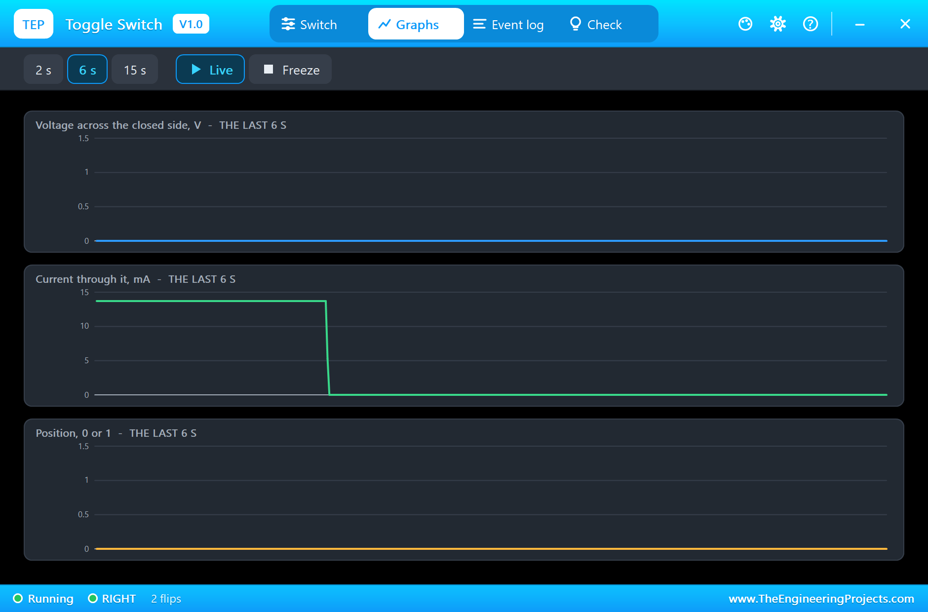
Now click SW1. The handle throws across to the left and the lamp comes on, carrying 13.7 mA through both switches. Here is the complete circuit, truly running:
The Graphs tab of SW1 follows the current through the closed contact. At the end of the run, you can see it stop as the second switch opened the circuit:
Flip SW2
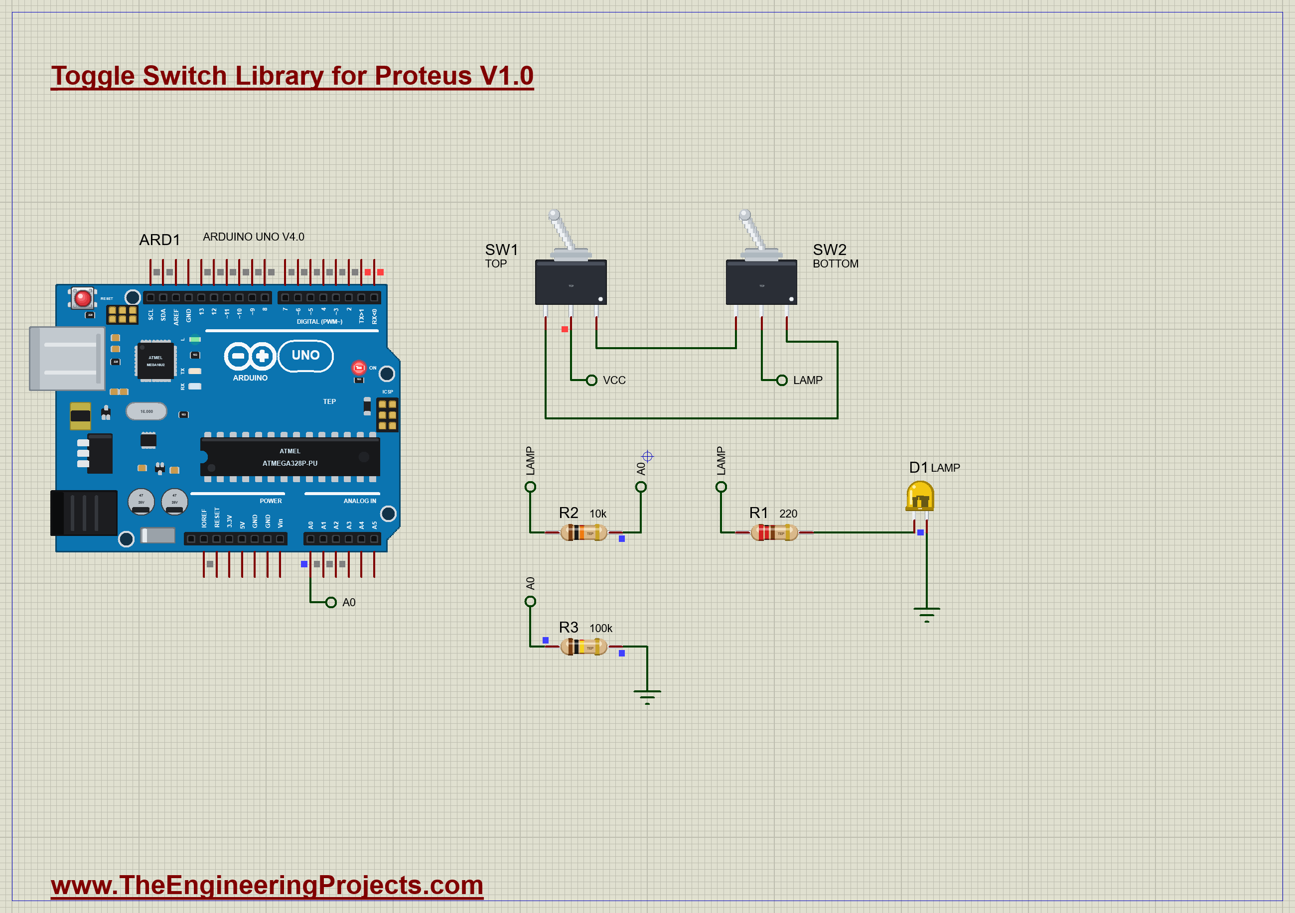
Click SW2, the switch at the other end. The lamp goes out, although SW1 has not moved. Both handles now lean to the left:
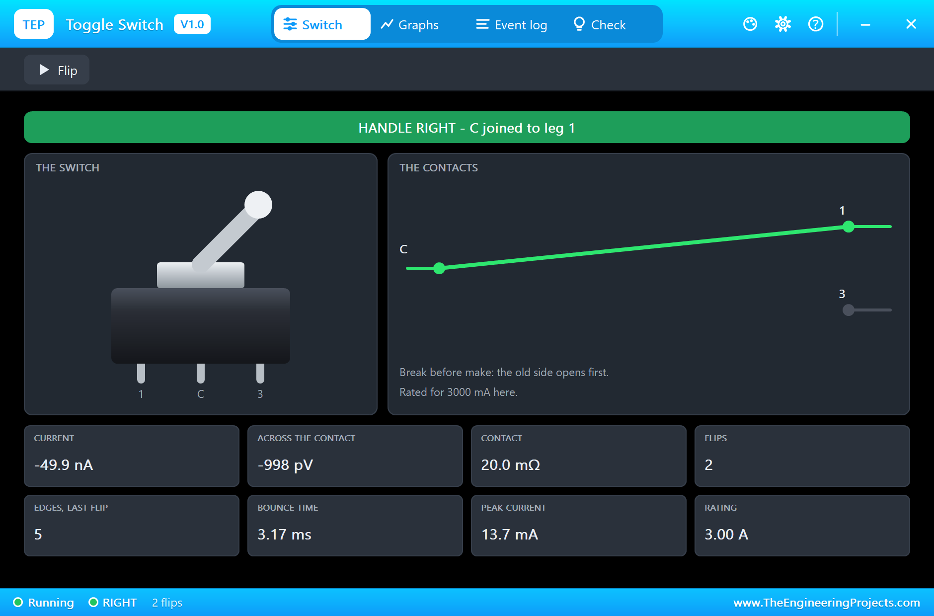
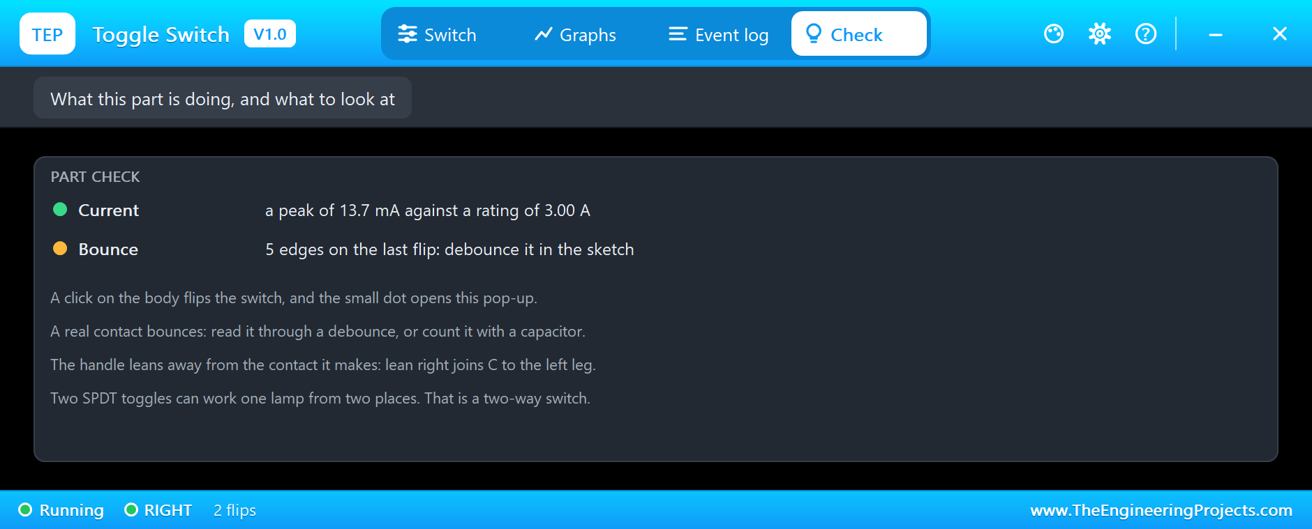
Look at SW2's pop-up after a couple of flips. The Edges tile shows that the contact made 5 edges as it landed, and the Bounce time tile shows that it was all over in about 3 ms. The peak current is that same 13.7 mA, far below the 3 A rating:
Now Go Back the Other Way
Click SW1 again. The lamp comes back on, with both switches in new positions compared with the last time it was lit. That is the two-way lamp at work: there is no "on" position, only agreement and disagreement.
Stop the simulation, and look at the sheet. The handles stay where you left them, and they will start there at the next Run.
The monitor keeps the score. In this run, the sketch saw all four changes, and it adds up the time the lamp has spent on:
The Log and the Check Page
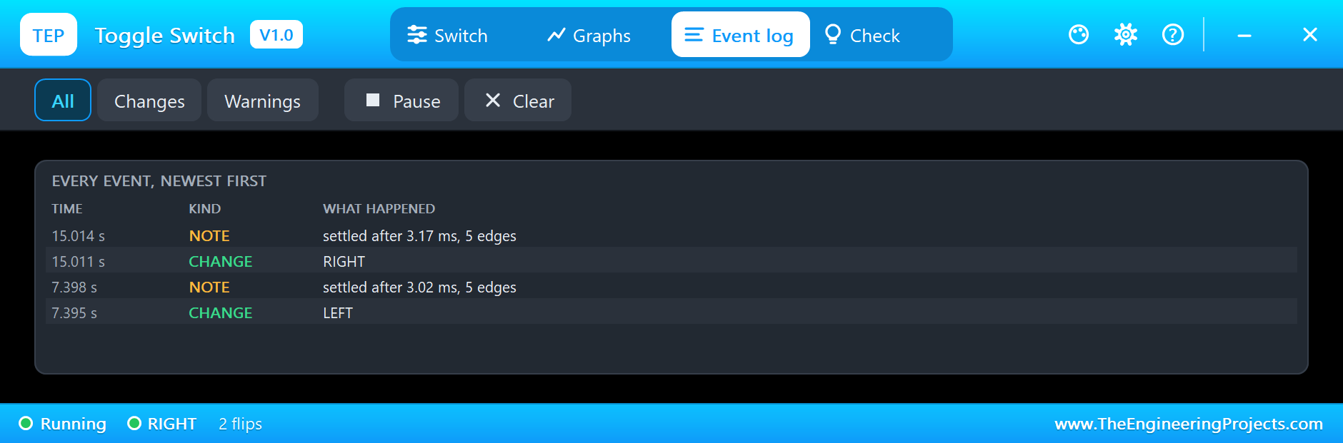
The Event log writes down each flip and how it settled. Here, the two flips of SW2 took 3.02 ms and 3.17 ms, with 5 edges each. The Check page looks at the current against the rating, and at the bounce. The amber mark on the bounce line is a reminder, not a fault: it means a sketch reading this contact should debounce it, and ours does.
Try It Yourself
- Swap the travellers so they run from leg 1 to leg 1, and from leg 3 to leg 3, and work out which positions now mean on.
- Set the bounce to 30 ms, and see how the 20 ms debounce in the sketch copes.
- Remove R3, and watch the reading on A0 when the lamp is off.
- Add a second lamp in parallel with the first, and see the current double in the pop-up.
- Add a buzzer that sounds if the lamp has been on for more than a minute.
Ideas to Extend the Demo
- Build a three-switch version, with a pair of toggles in the middle standing in for a DPDT part.
- Use one toggle to pick the direction of a motor through a driver.
- Make a row of four toggles that sets a number from 0 to 15, with an LED on each.
- Print a running electricity bill for the lamp, using the time it has been on.
Your Own Sketches
The demo sketch is in the zip file, and you can change it in the Arduino IDE. New to Arduino? Start with our Arduino Tutorial for Beginners. Export the compiled binary, and set the UNO's PROGRAM property to the new file. Our guide on How to get the HEX file from Arduino shows you where the file ends up.
Things to Know Before Using a Real Toggle Switch
- Check both ratings: the current and the voltage go together, and DC is far harder on a contact than AC.
- Keep the mains away from a metal handle: a panel for mains voltage needs proper insulation and an earth. Leave that wiring to a qualified person.
- Solder quickly: the body is plastic, and too much heat lets the lugs move inside it.
- Do not leave the lugs bare: use heat-shrink tube, since a loose wire can reach the next lug.
- Tighten the nut by hand and a little more: a stripped thread leaves a loose switch that spins in the panel.
Troubleshooting
- A click opens the pop-up: you clicked the small dot. Click the body or the handle to flip it.
- The handle seems to lean the wrong way: it leans away from the leg it joins, exactly as a real toggle does.
- The lamp is on at the start: the two switches agree. Flip either one, or set the Position while stopped box.
- The sketch sees several changes: that is contact bounce. Debounce it, or set the bounce to 0.
- A0 reads a strange value when the lamp is off: check R3, which holds the pin down when the wire is joined to nothing.
- The part is not simulated:
TEPTOGGLE.DLLis missing from MODELS and from the project folder.
Limitations of the Simulation
- The bounce follows a fixed pattern, with a real-looking spread, not a measured one.
- The arc on a heavy load, wear and the feel of the snap are left out.
- The rating is a warning on the Check page, for the current only: a real contact would pit or weld.
- Arduino is a name of Arduino; this library is not made or endorsed by Arduino or Labcenter.
- Tested in Proteus 8.5 in October 2026 (the demo as shipped). Proteus 7 is not supported.
So, that was all about the Toggle Switch Library for Proteus. I hope you enjoy that little chrome lever on your sheet, and that the next time you walk up the stairs and turn the light off from the top, you think of those two travellers doing their quiet job. If you have any questions, ask in the comments and I will help you out. Till the next tutorial, take care and have fun!