LED Flashing Project with 555 Timer in Proteus
Hello friends, hope you all are fine and enjoying life. In today's tutorial, I am gonna show how to do
LED Flashing Project with 555 Timer in Proteus ISIS. Its quite a simple project and usually done by engineers in their first or second semester. I have done this project in my first semester and have learned quite a lot from it. I recently done it on Proteus so thought of sharing it with you guys. It will also work on hardware as I have tested it.
In this tutorial, we will first have a look at How to do single LED Flashing with
555 Timer in Proteus ISIS. And afterwards, we will also see how to flash two LEDs with 555 Timer in
Proteus ISIS. Its quite simple and anyone one with basic knowledge of electronics can design it in his first attempt. Still if you get into any trouble, then ask in comments and I will try my best to resolve your issues, but I don't think its gonna happen as its quite basic. So let's start with this project:
Single LED Flashing Project with 555 Timer in Proteus ISIS
- First of all, copy these components from the Proteus components library:
- After selecting these components, now design a circuit in Proteus as shown in the below figure:
- Now when you click on RUN button in PRoteus ISIS, the LED will kep on flashing,it will go ON for 1 sec and then go OFF as shown in below figures.
- State # 1 is showing the OFF state of LED while the State # 2 is showing the ON state of LED.
- So, it will keep on flashing unless you Stop the Proteus ISIS simulation.
- You can download this simulation by clicking on the below button.
Download Single LED Flashing with 555 Timer in Proteus
Double LED Flashing Project with 555 Timer in Proteus ISIS
- In the above portion, we have seen how to flash a single LED with 555 Timer in Proteus ISIS, now let's flash two LEDs with 555 Timer in Proteus ISIS.
- First of all design a circuit as shown in below figure:
- As you can see its quite similar to the above project for single LED flashing with 555 timer in Proteus ISIS but has small changes in thhe values of resistor.
- So, now when you hit RUN button on Proteus ISIS then these LEDs will start flashing one after another, means when first LED is ON then the second one will be OFF and vice versa.
- Below figures are showing their ON OFF states:
- State # 1 is showing the OFF state for both the LEDs, while State # 2 is showing the ON state for first LED and OFF state for second and in third State first LED is OFF while the second LED is ON.
- So, this simulation will work in this way, if first LED is ON then the second one will be OFF and vice versa.
- You can download this second simulation by clicking on the below button:
Download 2 Led Flashing Project with 555 Timer in Proteus
That's all for today, in the coming post we will have a look how to design a traffic signal flasher with 555 timer in Proteus ISIS, which is gonna be quite exciting tutorial, so let's meet in the next tutorial. Till then take care and have fun !!! :)
Installation of Arduino driver in Windows
In today's tutorial, we are going to see how to install Arduino driver in Windows. In the previous post, we have seen what is Arduino? and why is it so popular and whats its use? Now, afer getting the basic knowledge of Arduino, the next step you need to do is to install Arduino driver in your computer so that it got recognized by your computer as Arduino. If you don't install the Arduino driver in Wndows then you won't be able to program Arduino using Arduino software.
tis tutorial is quite basic and is for the newcomers, who wants to start working on the Arduino software, if you have already run some codes on your Arduino then its not for you. You can skip it. Anyways, It's quite easy and it won't take much time. So let's get started with it.
Installation of Arduino driver in Windows
- First of all, download the Arduino software from Arduino official website. Download the most reent version of Arduino software, which is 1.6.3 while writing this post.
- After downloading the software, now plug your Arduino USB into computer.
- You will hear a small beep and Windows will try to intall the driver itself, but finally a yellow box will appear on the taskbar saying driver can't be installed.
Note:
- If you haven't bought your Arduino UNO yet, then you can buy it from this reliable source:
- So, now right click on your My Computer, open properties, then click on Device Manager and you will get a Window as shown in below figure:
- Now click on Other devices which is encircled in the above figure and you will get a new element named as Unknown device. This Unknown device is actually our Arduino UNO on which we are going to install the driver.
- Right click this Unknown device and then click on the Update Driver Software.
- As you click on it, it will give you two options so click on the below one which says Browse My Computer For Driver Software.
- On clicking it, you will get a Browse option, so now Browse in the Arduino software folder which you downloaded from the Arduino website and then open the drivers folder as shownin below figure and then hit NEXT button.
- After clicking the Next button, it will start installing the driver as shown in below figure:
- After the successful installation, it will show a window as shown below:
- So, now we have succesfully installed the Arduino driver for Windows and if you check it has also assigned the Com Port to Arduino, which is COM16 in my case, as shown in above figure.
- It will also be updated in the Device Manager as shown in below figure:
- That's it, Arduino driver in Windows is succesfully installed and now you can use it and can upload the programming code in it, which we will see in the next post.
Hope it helped you in some way. Let's meet in the next post. Take care and have fun.
What is Arduino ?
Hello friends, today I am posting a very basic tutorial on what is Arduino ??? In this tutorial I am gonna explain the basics of Arduino for the beginners. I am writing this tutorial because I got a lot of requests from the engineers in which they ask questions like what is Arduino ? What's the difference between Arduino and PIC? How to use Arduino? etc etc. So I thought of writing this topic. It's a very basic tutorial so if you are already familiar with this board and know the answer of this simple question
What is Arduino ??? then you can skip this tutorial but again you must read it once, may be you get something out of it. :)
I have posted a tutorial on Arduino Projects, in which I gave all the links of Arduino projects and tutorials posted on my blog, that's another reason for posting this tutorial. I am treating that Arduino Projects page as an ebook on Arduino so I am gonna post everything about Arduino as much as I can. And an ebook must have an intro chapter, which will be this one. So, let's get started.
What is Arduino ???
- Arduino is nothing but a simple microcontroller board which is normally used in engineering projects where there's a need to automate something.
- You can interface sensors with this board, can drive motors with this board, can plug switches in it etc.
- In old ages ( not old enough :P ), people used simple switches for turning ON a bulb so like you click the switch and the bulb is ON, it was quite a simple circuit, after that relays are invented and then engineers used 555 timer circuits in order to turn ON lights on some specific time. But the 555 timer circuits are quite big in size, so finally engineers discovered Microcontrollers in which there are simple OUTPUT and INPUT pins, so now if you want to turn on light at some certain time then you just simply plug the blub on output pin of microcontroller and then do some programming and add a timer to automatically turn on the bulb.
- So, the benefit of microcontroller is the circuit is quite simple and small in size.Moreover, its flexible, suppose you want to change the time of turning ON bulb then what you need to do is simply change the coding and it will be changed, but in 555 timer circuits you need to change the components in order to do so.
- Now, we know the use of microcontroller and also their benefit but thing is what is Arduino ??? In microcontrollers like PIC or Atmel, there's a small drawback.
- Suppose you want to work on PIC then you have to first design its basic circuit also need to design a power circuit to supply power to it and after that in order to upload the code in it, you have to buy a programmer/ burner as well. So, first of all you need to write the code for PIC Microcontroller and after that you need to upload code in it using a programmer and then plce PIC microcontroller back into the circuit and test, which is quite lengthy plus also got hectic when you are working on some project because you have to test code again and again.
- By the way, now advance programmers like PICkit2 and PICkit3 can be plugged on board but still you have to design the basic circuit so coming to bottom line, in order to do project with PIC or Atmel microcontroller you have to do soldering etc.
- But that's not the case with Arduino Board, Arduino has built in programmer and the basic circuit in it. So what you need to do is simply plug in Arduino with your computer via usb cable, get its software and start uploading code and also start testing.
- So, you don't need to plug unplug or do anything, simply upload the code and test. Moreover, it also has some very efficient tools using which you can test your output as well quite easily. Arduino board also has the pins on which you can simply plug your devices and can turn them ON or OFF. So, hats off to Arduino team for providing us a simple board which has everything on it.
- Another advantage of Arduino is that, because of its popularity all the electronic components also have the Arduino libraries which are free and using them you can operate that electronic component quite easily with Arduino. Its open source and hence its developing day by day.
Types of Arduino Boards
- There's a long range of Arduino boards available online, the basic Arduino board is named as Arduino UNO which is most widely used in projects.
- Arduino UNO has total 13 digital pins and 6 analog pins which are used for connecting sensors with them.
- Suppose you have a project in which you want to interface 30 sensors, then what you need to do ?? Now you need to buy another Arduino board named as Arduino Mega 2560. This board has around 70 pins on it which can be used as output or input and hence you can plug your sensors quite easily.
- Moreover, Arduino have also developed different shields like Arduino Ethernet shield. Using this shield you can provide internet access via Ethernet to your project.
- Then they have Arduino Wifi shield which is used for providing Wifi access to your project.
- They have also developed Arduino GSM shield for GSM or GPRS purposes, in short there's a wide range of Arduino boards available online.
- So which Arduino board you need to buy depends on the requirements of your project.
How to use Arduino ??
- Now I think you have got the basic idea of what is Arduino ? and why is it so popular ? So now lets have a look at how to use Arduino.
- When you order for your Arduino board, you will get a package similar to the image below:
- Along with this box, you will also have the USB cable, now take your Arduino board out of this box and plug the cable in it, connect the Arduino with your computer and you are ready to start working on it.
- In order to connect Arduino with your computer you have to install the Arduino drivers in Windows.
That's all for today, hope I have conveyed some knowledge and you now know the basics of Arduino i.e. what is Arduino ? and why to use Arduino.
Interfacing of Seven Segment with Arduino in Proteus
Hello friends, today we are gonna have a look on how to interface Seven Segment with Arduino in Proteus. In my last post, I have posted an Arduino Library for Seven Segment Display, which is designed by our team and is quite basic in functionality. So, if you haven't checked that post then first of all check that one and download the Arduino Library for Seven Segment Display as I am gonna use that library in today's post. Moreover, in order to run this library you are also gonna need to download Arduino Library for Proteus, using this library you will be able to use Arduino board in Proteus so also read that post and download this library and install it in your Proteus.
Again I am mentioning that its the first library designed by our team so its in basic stages, it has few functions and will only display the numeric on the seven segment display which is normally required. I am planning on adding more examples in the library for future use, which will increase the functionality. Anyways that's a future talk, let's start today's post.
What is Seven Segment Display?
Let's first have a look at what is Seven Segment Display. Seven Segment display is nothing but an electronic device used for displaying the numeric data. It's a complex form of LED matrix and is normally used in clocks, LCD displays, calculators etc where there's a need to display the numeric data. It has total seven leds in it which you can also count from above image and by turning these LEDs ON or OFF we can display any numeric on it. For example, have a look at the below image. In this image I have shown numeric 0 on seven segment. Now in order to do so, I just simply turn OFF the centered LED and turn ON all the corner LEDs and it becomes 0.
How does Seven Segment Work?
Now, let's have look at how it works. So, we have seen that Seven Segment is named seven segment because it has total seven LEDs on it so now what we need to do is to control these seven LEDs, also named as segments, and then we can display any character on it. There are two types of seven segments available in the market and named as:
- Common Cathode
- Common Anode
They both work exactly the same and has only a slight difference. They both has total seven pins and each pin is used to control each led and they have an extra pin which is named as Common Pin. In Common Cathode you have to GND this Common Pin, while in common Anode, you have to give +5V to this Common Pin. Have a look at this below image, we have labelled leds with respect to the pins.
Interfacing of Seven Segment with Arduino in Proteus
- Now we know all about Seven Segment Display and know how it works so let's interface Seven Segment with Arduino in Proteus.
- Now, I am assuming that you have installed the Arduino Library for Proteus and have also installed the Arduino Library for Seven Segment display.
- So, now open your Arduino Software and go to File>Examples>SevenSegment>Counting.
- Open this example, in this example I have added a counter which will start counting from 0 to 9 and once it reached 9 then it will start counting again.
- If you can't find this example then you must be making some mistake in installing the library, anyways the code is shown below.
Note:
- In order to run this example you will need two libraries, the inks are given below to download:
/*
Counting
This Arduino example is for Seven Segent display.
It will start the counter from 0 and will end up at 9
and will start again from 0.
This example code is in the public domain.
Created by Syed Zain Nasir at 14 March 2015.
You can get the explanation and latest version of this library at:
http://www.TheEngineeringProjects.com/
*/
#include "SevenSegment.h"
SevenSegment tep = SevenSegment(0,1,2,3,4,5,6);
char arr [10] = {'0','1','2','3','4','5','6','7','8','9'};
int index;
void setup(){
index = 0;
}
void loop(){
tep.display(arr[index++]);
delay(1000);
if(index == 11)
index = 0;
}
- Now open you Proteus Software and design the circuit in it as shown in below figure, I have also attached the file for download at the end.
- Now compile the code and gt the hex file and upload it in your Arduino Properties.
- Now Run the Proteus software, and you will see the seven segment display will start counting, a glimpse of it is shown in the below figure:
- Below is attached the Proteus file and the hex file for the counting example which you simply start and run but again I suggest that you should design it by yourself so that you get something out of it.
Download Proteus Simulation of Seven Segment with Arduino
- One last thing, any kind of contribution to this library from the readers is highly appreciated, design your projects and share codes with us and we will post them on our blog for other readers to get knowledge as knowledge is all about sharing.
That's all for today, hope it will help you in some way. Take care and have fun. :)
Arduino Library for Seven Segment Display
In today's post, I am gonna share a new Arduino Library for Seven Segment Display. In my recent project, I got a chance to work on seven segment displays, I have worked on them using PIC microcontroller but haven't got a chance to use them with Arduino. So, now as usual when I started working on them, I started searching for Arduino Library but I kind of got disappointed after getting quite heavy libraries for seven segments, and after a lot of search I thought of designing my own Arduino library for seven segment display, which I am gonna share in this post. :)
It's not very advanced library as we know seven segment displays are not too complex, so its quite simple and using it you can quite easily display any numerical digit on the seven segment display. Moreover, I have also included an example with the library which will start the counter from zero on seven segment display and keep on incrementing till 9 and after that it will start again from zero. Moreover, I have also posted the example about Interfacing of Seven Segment Display with Arduino in Proteus using this library, it will help you in better understanding of How this library works. You can download the working Proteus Simulation as well as hex file from that post.
Download Arduino Library for Seven Segment Display
- As I stated earlier, its a very simple Arduino Library for Seven Segment Display and it will only print the numeric on seven segment display, but I will work on it in future and will update it by adding more features in it.
- So, first of all click the below button to download the Arduino library for seven segment display.
Download Arduino Library for Seven Segment Display
- After downloading the library, place it in the libraries folder of your Arduino software.
- Now close your Arduino software and open it again.
- Go to File and then Examples and you will find SevenSegment in it and it will have an example which is named as Counting.
Functions in Arduino Library for Seven Segment Display
- I have added quite few function in it which are very basic and are very easy to use.
- The first function I have used is:
SevenSegment(int a,int b,int c,int d,int e,int f,int g);
- In this function, you need to give the pins of Arduino with which you are attaching your seven segment display. It will called as shown below:
SevenSegment tep = SevenSegment(0,1,2,3,4,5,6);
- Now tep is our seven segment object and we are gonna use it in rest of the example.
- The next function used in this arduino library for seven segment display is:
display(char c);
- This function will display the numeric on seven segment display which you will provide it.
- Moreover, it will automatically clear the screen before displaying any new character on the seven segment.
- It is called in the example as shown below:
tep.display('1');
That's all for today, in this next post you can download the example of how to
Interface Seven Segment Display Using Arduino in Proteus, it will help you in understanding of this library in detail.
Temperature Sensor 18B20 with Arduino
Hello everyone, in today's post we are gonna have a look at how to interface temperature sensor Dallas 18B20 with Arduino. There are many temperature sensors available in market like LM35, DHT11 etc but personally I like Dallas18B20 most of all, as it gives the most accurate result up to four decimal points. It operates on single wire and sends all data through this wire. Another advantage of this wire is you can interface multiple sensors with a single data line. You should also have a look at How to use 18B20 in Proteus ISIS.
In today's post, we are gonna get value from this sensor and then print it over the Serial Terminal as well as LCD. We will get the values in degree centigrade. Its not much difficult to interface 18B20 with arduino and also an Arduino library is also availble, using which you can quite easily interface 18B20 with Arduino. Let's get started with interfacing of 18B20 with Arduino.
Note:
Interfacing of Temperature Sensor 18B20 with Arduino
- As I explained earlier, it works on single wire and hence we are gonna need 1-wire library for Arduino along with 18B20 arduino library.
- Download both of these libraries by clicking on the below buttons:
Download One Wire Library Download Dallas Temperature Library
- After downloading the library, place it in the libraries folder of your Arduino Software.
- Now restart your Arduino software and you will find the Arduino folder in the Examples section.
- Next we need to interface our sensor 18B20 with Arduino so design your circuit as shown in below figure:
- So, connect the sensor 18B20 with Arduino as shown in the above figure, connections are quite simple and are as follows:
- Pin # 1 of 18B20 with GND
- Pin # 2 of 18B20 with Pin # 2 of Arduino.
- Pin # 3 of 18B20 with GND of Arduino.
- Add a pull up resistor of 4.7k ohm at pin # 2 of 18B20.
- Here's the images of hardware, we designed for this project, its a 20 x 4 lcd we have used:
- Below image shows the small 18B20 sensor, used in this project, it looks small but very efficient.
- Here's the image showing the complete project:
- Now, copy below code and upload it in your Arduino board and open your serial terminal.
#include <OneWire.h>
#include <DallasTemperature.h>
#include <LiquidCrystal.h>
#define ONE_WIRE_BUS 2
OneWire oneWire(ONE_WIRE_BUS);
DallasTemperature sensors(&oneWire);
LiquidCrystal lcd(12, 11, 7, 6, 5, 4);
void setup(void)
{
Serial.begin(9600);
Serial.println("Welcome to TEP !!!");
Serial.println("www.TheEngineeringProjects.com");
Serial.println();
sensors.begin();
lcd.begin(20, 4);
lcd.setCursor(5,0);
lcd.print("Welcome to:");
lcd.setCursor(1,2);
lcd.print("www.TheEngineering");
lcd.setCursor(4,3);
lcd.print("Projects.com");
delay(5000);
}
void loop(void)
{
sensors.requestTemperatures();
Serial.print("Temperature : ");
Serial.println(sensors.getTempCByIndex(0));
//lcd.clear();
lcd.setCursor(0,0);
lcd.print("Temperature: ");
lcd.print(sensors.getTempCByIndex(0));
lcd.print("C");
delay(1000);
}
- After uploading the code, when I start the project, it started showing the temperature values as shown below:
- As you can see, its giving the temperature of my room which is 23.56 degree centigrade.
- I have also designed a video for more demonstration which is given below:
- It's quite a simple code and is self explanatory but still if you need help ask in comments and I will help you out.
Interfacing of Multiple Ultrasonic Sensor With Arduino
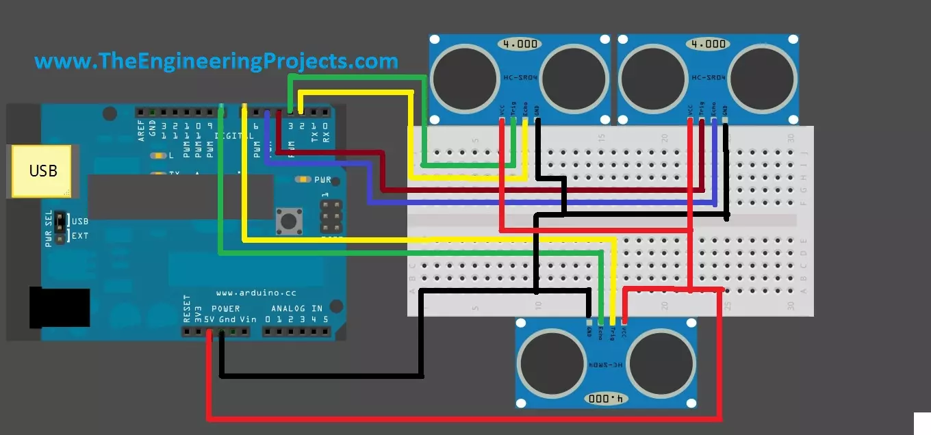
Hello friends, hope you are having fun and enjoying life. Today, I am gonna post about interfacing of multiple Ultrasonic sensor with Arduino. In the previous post, we have seen Interfacing of Ultrasonic Sensor With Arduino and in this post I have interfaced single ultrasonic sensor but in projects especially related to robotics, we have to interface multiple ultrasonic sensors. For example you have an obstacle detection robot, now in order to detect obstacle in front of robot you have to place once sensor on the front side but now you can't detect any object present on left or right side of your robot, so you have to place two sensors one on the left side of robot and one on the right side so in this project you need to use total three ultrasonic sensors, one on the front, one on left and one on right side of robot. Similarly, in another project I have to move the robot in a maze having walls on the side of robots, and my task was to move the robot straight within these walls without hitting the walls. In that case, I also used two ultrasonic sensors on both sides of robot and then applied PID algorithm in order to avoid hitting the walls. So, in short its a common practice to use multiple ultrasonic sensor with Arduino and today we are gonna have a look at how to do it.
I have posted about the basics of Ultrasonic sensor and how it works in my previous post so I am not gonna go into that detail. If you haven't read it then I recommend that you should first read Interfacing of Ultrasonic sensor with Arduino. Now, let's get started with Interfacing of multiple ultrasonic sensor with arduino, which isn't that difficult. :)
Note:
- Other Proteus Libraries are as follows:
- I have also posted more examples on Ultrasonic Sensor Simulation in Proteus, have a look at them and you will get complete understanding of this sensor.
- Moreover, for hardware implementation of Ultrasonic Sensor with Arduino, check below posts:
Interfacing of Multiple Ultrasonic Sensor With Arduino
- Let me first summarize the working of ultrasonic sensor again. With ultrasonic sensor, what we need to do is to generate a trigger signal on its trigger pin for around 10 microsecond.
- As soon as the ultrasonic sensor gets this trigger signal, it sends out an ultrasonic signal.
- This ultrasonic signal then hits something and bounced back.
- Now, in order to check this bouncing signal, we have to read the Echo pin and check for how long it remains HIGH, and on the basis of this duration we calculate our distance with the object.
- This is the process for single ultrasonic sensor and when we are using multiple ultrasonic sensors, what we need to do is simply repeat the whole procedure for all the sensors one by one.
- First of all, we will generate the trigger pulse for first sensor and the read its echo pin and get the distance, then we generate the trigger pulse for second sensor and read its echo pin and so on for the third.
- So, here I am gonna use three ultrasonic sensor and the circuit diagram is shown below:
- I have tried my best while designing this image to make it simple but as there are too much wires so it has become a little complex.
- I am pointing out the pin configuration here so it will be easy for you to interface your sensors with arduino. The pin configuration is as follows:
- Vcc of all sensors will go into +5V of Arduino.
- GND of all sensors will go into GND of Arduino.
- Trig Pin of first sensor into Pin # 3 of Arduino.
- Echho Pin of first sensor into Pin # 2 of Arduino.
- Trig Pin of second sensor into Pin # 4 of Arduino.
- Echo pin of second sensor into Pin # 5 of Arduino.
- Trig Pin of third sensor into Pin # 7 of Arduino.
- Echo pin of third sensor into Pin # 8 of Arduino.
- After connecting the pins as discussed above, now copy the below code and upload it in your arduino board.
- After uploading the code in your arduino, open the Serial Terminal of Arduino software and you will start receiving the distances for all the three sensors.
#define trigPin1 3
#define echoPin1 2
#define trigPin2 4
#define echoPin2 5
#define trigPin3 7
#define echoPin3 8
long duration, distance, RightSensor,BackSensor,FrontSensor,LeftSensor;
void setup()
{
Serial.begin (9600);
pinMode(trigPin1, OUTPUT);
pinMode(echoPin1, INPUT);
pinMode(trigPin2, OUTPUT);
pinMode(echoPin2, INPUT);
pinMode(trigPin3, OUTPUT);
pinMode(echoPin3, INPUT);
}
void loop() {
SonarSensor(trigPin1, echoPin1);
RightSensor = distance;
SonarSensor(trigPin2, echoPin2);
LeftSensor = distance;
SonarSensor(trigPin3, echoPin3);
FrontSensor = distance;
Serial.print(LeftSensor);
Serial.print(" - ");
Serial.print(FrontSensor);
Serial.print(" - ");
Serial.println(RightSensor);
}
void SonarSensor(int trigPin,int echoPin)
{
digitalWrite(trigPin, LOW);
delayMicroseconds(2);
digitalWrite(trigPin, HIGH);
delayMicroseconds(10);
digitalWrite(trigPin, LOW);
duration = pulseIn(echoPin, HIGH);
distance = (duration/2) / 29.1;
}
- The code is quite similar to the one we used while interfacing single ultrasonic sensor with arduino, the only thing we changed here is the repetition.
- Before, we were using the same function SonarSensor() but calling it only once for our single sensor interfaced with arduino but now we are calling it three times for all the three sensors.
- Its kind of a generic code, you can interface more sensors with it if you want and what you need to do is only calling this function for the next interfaced sensor.
That's all for today, I think we have posted a lot on the ultrasonic sensor so I am not gonna post any more tutorial on this sensor and now I will start writing on some other sensor. You should also have a look at
Arduino Projects for Beginners. Thanks for reading and share it with your friends and help us grow. :)
Interfacing of Ultrasonic Sensor With Arduino
Today, we are gonna have a look on How to Interface Ultrasonic Sensor with Arduino. Few days ago, I have posted a complete tutorial on How to Use Ultrasonic Sensor Library in Proteus and later I have posted different examples on How to Simulate Ultrasonic Sensor in Proteus. Those posts were about Proteus Simulations and weren't about hardware interfacing, so I thought today let's interface it in hardware.
Simulation is a good starting point for projects but they are really far away from real world. It happened to me a lot of times that my simulations are working perfectly fine but when I design the same circuit in hardware then it says no I am not gonna work. :) So, the bottom line is never trust simulations, unless you properly test it on hardware. So, today I am gonna interface an Ultrasonic sensor with arduino and will check its output on the Arduino Serial Terminal.
1. Introduction to Ultrasonic Sensor
- "Ultrasonic Sensor HC-SR04 is a simple sensor which emits Ultrasonic Radiations from its transmitter and is used for measuring the distance between sensor itself and any obstacle in front of it. The sensor has a transmitter and a receiver on it."
- This sensor consists of four pins, which are:
- Vcc (+5V) : You need to provide +5V at this Ultrasonic Sensor HC-SR04 Pin.
- Trig (Trigger) : It's a trigger Pin where we need to provide a trigger after which this sensor emits ultrasonic waves.
- Echo : When Ultrasonic waves emitted y the transmitter, hit some object then they are bounced back and are received by the receiver and at that moment this echo Pin goes HIGH.
- GND : We need to provide ground to this PIN of HC-SR04 Ultrasonic Sensor.
Note:
- If you haven't bought your components yet for this project, then you can buy them from these reliable sources:
[ultimate_spacer height="13"]
|
[ultimate_spacer height="13"]
|
- Trigger pin is an output pin while the Echo pin is an input pin, we will discuss them in Working section in detail.
- Moreover, it requires +5V to start operating.
- It is normally used to detect objects in front of it or to measure the distance between different objects.
2. Working of Ultrasonic Sensor
- Its working is quite simple, as discussed above, it has a trigger and an echo pin.
- A signal of +5V is sent over to Trigger pin for around 10 microseconds in order to trigger the sensor.
- When ultrasonic sensor gets a trigger signal on its trigger pin then it emits an ultrasonic signal from the transmitter.
- This ultrasonic senor, then goes out and reflected back after hitting some object in front.
- This reflected ultrasonic signal is then captured by the receiver of ultrasonic sensor.
- As the sensor gets this reflected signal, it automatically make the Echo pin high.
- The time for which the Echo pin will remain HIGH, depends on the reflected signal.
- What we need to do is, we need to read this time for which the echo pin is high, which we are gonna do in our next section.
- So, let's have a look at Ultrasonic Sensor Arduino Interfacing.
3. Interfacing of Ultrasonic Sensor With Arduino
- Now we have seen the working of Ultrasonic sensor, so we have some idea what we need to do in order to get the values from it. Let's now have a look at Ultrasonic Sensor Arduino Interfacing.
- First of all, we need to generate a signal of 10 microsecond and then send it over to trigger pin.
- After sending the trigger pin we then need to read the echo pin and wait for it to get HIGH.
- Once it got HIGH then we need to count the time for how long it remained HIGH.
- On the basis of this time, we are gonna calculate the distance of the object from the ultrasonic sensor.
- So, first of all, interface your ultrasonic sensor with arduino as shown in below figure:
- Now, use the below code and upload it your arduino board. After uploading the code, open your serial terminal of Arduino software and you will start receiving the values.
#define trigPin1 8
#define echoPin1 7
long duration, distance, UltraSensor;
void setup()
{
Serial.begin (9600);
pinMode(trigPin1, OUTPUT);
pinMode(echoPin1, INPUT);
}
void loop() {
SonarSensor(trigPin1, echoPin1);
UltraSensor = distance;
Serial.println(UltraSensor);
}
void SonarSensor(int trigPin,int echoPin)
{
digitalWrite(trigPin, LOW);
delayMicroseconds(2);
digitalWrite(trigPin, HIGH);
delayMicroseconds(10);
digitalWrite(trigPin, LOW);
duration = pulseIn(echoPin, HIGH);
distance = (duration/2) / 29.1;
delay(100);
}
- Now if you check in the SonarSensor() function, we are generating a pulse of 10 microsecond and sending it to trigPin, which is the trigger pin of our ultrasonic sensor.
- After sending this pulse weare using a funcion pulseIn() , its a builtin arduinofunction and is used to check for how long the echoPin remains HIGH.
- This value is further saved in the duration value and after that we have divided this duration by 2 because the pulse is first sent and then received so in actual it covers double distance, so we need to divide it by 2 in order to get distance between object and the sensor.
- Furthermore, it is again divided by 29.1, which is basically the speed of ultrasonic sound and finally we saved it in a variable named distance which is now in centimeters.
- After uploading the sketch in Arduino, you need to open the Serial Terminal and you will start receiving the values of distance.
That's all for today. I hope you have enjoyed this Interfacing of Ultrasonic Sensor with Arduino. It wasn't that difficult, in our coming post we are gonna
Interface Multiple ultrasonic sensors with Arduino and will get their values on the serial terminal. Till then Take care and have fun !!! :)
Receive SMS with AT Commands using Sim900 and Arduino
Update: I have updated the code and removed the bug. Thanks for informing. Now this code will work perfectly.
Buy This Project
Hello friends, hope you all are fine and having good health. Today, as the name suggests, I am gonna post on how to Receive SMS with AT Commands using Sim900 and Arduino. I have already posted a tutorial on How to Send SMS with Arduino UNO and Sim900, so now we are gonna check the opposite. Sending SMS is quite easy, you just need to write some AT commands and write the message you wanna send and hit the Cntrl + Z and it will be sent. But receiving a text message on your SIM900 shield is a bit difficult because now you need to place a check when user will send a message. So, ideally whenever anyone send a message to your SIM900 module, you should get notified. Today, we are gonna cover this how to receive SMS with AT Commands in detail.
Now, after you get notified, there's a need to read the message as well and also who has sent this message. So, we are also gonna cover it today. So, first of all we will place a check that whenever someone sends a message to our SIM900 module, we get notified and after that we will extract the message and the mobile number of sender. We have designed this code after a lot of effort that's why this code isn't free but we haven't placed a very small amount of $20 so that engineering students can also buy it easily. We can also interface our GSM board with other microcontrollers like PIC Microcontroller as well as 8051 Microcontroller. I have also posted tutorial on How to Receive SMS with SIM900 & PIC Microcontroller and How to Send SMS with PIC Microcontroller so if you are working on PIC Microcontroller then you must give it a look. So, let's get started with How to receive SMS with AT Commands using SIM900 and Arduino.
You must also check GSM Library for Proteus, using this library you can easily simulate your GSM module in Proteus ISIS. Moreover, also have a look at Send SMS with Sim900D in Proteus ISIS in which I have designed a simulation of sms sending in Proteus ISIS.
Receive SMS with AT Commands using Sim900 and Arduino
- There are many GSM modules available in the market so it doesn't matter which one you are using unless its having SIM900 module in it.
- I have explained in my previous post that all GSM modules work on AT commands, so here first of all we are gonna have a look on AT commands we are gonna use for receiving the SMS.
- ATE0 - IT is used to turn off the Echo of GSM shield.
- AT - Just to check that your GSM module is working fine.
- AT + CMGF = 1 - This command will convert the message style to text. In other words we are telling our shield that we are expecting a text message.
- AT+CNMI=1,2,0,0,0 - This command will alert our GSM shield and now whenever it will receive message, it will automatically send an alert on the serial port.
- We are gonna use these four commands in our code and we will be able to receive text message on the GSM shield.
- Remember we have to put Enter after each of the above AT commands in order to execute it.
- Below is the first phase of the code and as you can see in this code we are simply sending these four commands serially from arduino to GSM shield.
- These are two functions I have shown below, the first function is Config() which is simply sending the commands via serially and then the Response() function which is called after every AT command and is receiving the response of that AT command.
- So, here's the partial code for How to Receive SMS with AT Commands using Sim900 and Arduino.
void Config()
{
delay(1000);
Serial.print("ATE0r");
Response();
Serial.print("ATr");
Response();
Serial.print("AT+CMGF=1r");
Response();
Serial.print("AT+CNMI=1,2,0,0,0r");
Response();
}
void Response()
{
int count = 0;
Serial.println();
while(1)
{
if(Serial.available())
{
char data =Serial.read();
if(data == 'K'){Serial.println("OK");break;}
if(data == 'R'){Serial.println("GSM Not Working");break;}
}
count++;
delay(10);
if(count == 1000){Serial.println("GSM not Found");break;}
}
}
- The response of these commands is shown below on the Serial Monitor of Arduino.
- For each AT command, we get a response "OK" from the GSM shield.
- Now, I know that I have sent all these four AT commands and my GSM shield is ready to receive the text messages and will inform me.
- So, when you send a message to your GSM shield, it will give a notification as shown in the below figure:
- Each message received by SIM900 module is start with "+CMT" and after that it has the mobile number of the sender and at the end lies the body of the message, which in our message is "www.TheEngineeringProjects.com"
- So now let's extract this mobile number and the text body from this CMT string.
Getting the SMS Text & Sender Mobile Number
- Till now we have learnt How to Receive SMS with AT Commands using Sim900 and Arduino and send you notification over the serial monitor.
- Now we have to place some checks in our code so that we could be able to get the required data out of this string.
- In order to do so, I am gonna first save this CMT string into an array, which I named as RcvdMsg[index].
- But before saving the data into this string, first I need to make sure that I am actually getting the requried string, that's aso possible that I am receving some garbage values.
- So, I placed a check first, which is checking for these four characters "+CMT", and when I got these character on my serial terminal I got sure that I have the string ready so I made the index = 0 and starting receving the string.
- Next thing I need to do is make sure that I have got the complete string, that was really a tricky part as there's no end character in the string.
- So, I used "n" null character for that. If you check the string then you can see that we are getting two null characters in complete string.
- I placed this check that when I get 2 null characters means I have got the complete string so I stopped receving the string.
- After that I simply count the charaters, in my string the sender mobile number is at posting 4 to 16 so I made a loop and save it in another array. and similarly did for the message text.
- Now when I send message after uploading this final code into my Arduino board, I get the below result on my Serial Monitor.
- Isn't it cool :) So, now we have separated the complete text as well as the sender's mobile number from our GSM string and we can use it anywhere we want.
- We can use this mobile number in the previous post code and can reply some text back and can also give a missed call to the user, anything we want. I am gonna post on How to send a call using SIM900 in the next post.
- You can buy the codefor How to Receive SMS with AT Commands using Sim900 and Arduino from our shop by clicking the below button:
Buy This Project
- I have highlighted all the functions in the code.
- As I always say, understand it first and then write on your own and do mistakes so that you learn.
That's all for today. I hope you have enjoyed this project named Receive SMS with AT Commands using Sim900 and Arduino. I will meet you guys in the next post. Till then have fun !!! :)
Circuit Designing of LCD with Arduino in Proteus ISIS
Hello friends, I hope you all are doing great. Today, I am going to share Circuit Designing of LCD with Arduino in Proteus ISIS. In my previous tutorial, I have posted a tutorial on How to use Arduino Library in Proteus. Using that library, we can easily test Arduino code in Proteus to check whether its working or not. If you haven't read that post then before starting it, first read it, as without adding the arduino library we can't use Arduino in Proteus.
Coming to today's post, as we have done adding the Arduino Library in Proteus, so I thought to do some projects on it and the first one I chose is quite simple one i.e. Circuit Designing of LCD with Arduino in Proteus ISIS. So we will have a look on how to show some characters on LCD using Arduino in Proteus. If you are working on LCD then you should also have a look at my new post Scrolling Text on LCD using Arduino. Let's get started with Circuit Designing of LCD with Arduino in Proteus ISIS:
Circuit Designing of LCD with Arduino in Proteus ISIS
- First of all, design a circuit of LCD and Arduino in Proteus ISIS, if you have already added the Arduino Library then you won't find any problem in finding the Arduino in components library of Proteus.
- You should also download this New LCD Library for Proteus.
- Design the circuit as shown in below figure:
- Now, we need to design Arduino sketch for LCD, so open Arduino software and place below code into it.
- You should have a look at How to get Hex File from Arduino.
#include <LiquidCrystal.h>
LiquidCrystal lcd(12, 11, 5, 4, 3, 2);
void setup()
{
lcd.begin(16, 2);
lcd.print("www.TheEngineer");
lcd.setCursor(0,1);
lcd.print("ingProjects.com");
}
void loop() {}
Note:
- For Arduino code, I have used Liquid Crystal Arduino Library, which you can download from the below link and add it in the libraries folder of Arduino software.
Download LiquidCrystal Arduio Library
- If you haven’t bought your Arduino UNO and LCD yet, then you can buy it from this reliable source:
- Now compile the code, and get the Arduino hex file which will be in the tmp folder, you can read Arduino Library for Proteus to know in detail how to get the hex file of Arduino sketch.
- Now double click the Arduino in Proteus ISIS and properties window will pop up.
- In properties panel, under the Program File section, browse to Arduino hex file as shown in below figure and upload it.
- Now click Ok and Run your simulation, if everything goes fine then your LCD will start showing the characters as shown in below figure:
- You should also have a look at these Arduino Projects for Beginners.
- That's all, was it difficult ??? I dont think so :) Anyways, if you got into any trouble, do ask in comments.
- In the coming posts, we will explore Arduino in Proteus ISIS more. Till then take care !!!