XNOR Gate with Truth Table in Proteus ISIS


Hello Mentees!, I hope you have a productive day. Welcome to The Engineering Projects. In the previous lecture, we discussed the XOR Logic Gate and designed its circuit using basic logic gates i.e. AND, OR and NOT. Today, I am going to explain another Logic Gate named XNOR Gate in detail.
We are going to discuss these concepts in today's lecture:
- What are Exclusive NOR Gates
- Experimental Proof in Proteus ISIS.
- How Truth Table of Exclusive NOR Gate is designed.
- How is its Timing Diagram?
- Circuit of Exclusive NOR Gate in Proteus Simulation
- Applications of Exclusive NOR Gates
XNOR Gate
- The exclusive NOR Gate(also called XNOR Gate) simply inverts the output of the XOR Gate(we discussed in the last lecture).
- So, if we simply place a NOT Gate in front of the XOR Gate, we will get the XNOR Gate.
- The XNOR Gate is denoted by a plus sign with a circle around it between the inputs and a collective Complement or a Bar on the Expression.
- The symbolic representation of XNOR along with symbol and expression is shown in the below figure:
- The Truth Table of XNOR Gate is given next:
| A | B | Y |
| 0 | 0 | 1 |
| 0 | 1 | 0 |
| 1 | 0 | 0 |
| 1 | 1 | 1 |
Mathematical Expression of XNOR Gate
The XNOR Gate with 2-inputs(A and B) and 1 Output(Z) is represented by the following mathematical expression:
Z = (A)'.(B)' + A.B
So, we will need AND, OR and NOT logical gates to implement XNOR Gate. Let's first verify this equation by applying the truth table.
For 1st Row:
=(0)'.(0)'+0.0
=1.1+0.0
=1+0
=1
For 2nd Row:
Now, A=0, B=1
=(0)'.(1)'+0.1
=1.0+0.1
=0+0
=0
For 3rd Row:
Consider A=1, B=0:=(1)'.(0)'+1.0
=0.1+1.0
=0+0
=0
For 4th Row:
Lastly, A=1, B=1:=(1)'.(1)'+1.1
=0.0+1.1
=0+1
=1
Hence in accordance with the above discussion, let's design the circuit of the XNOR Gate in the Proteus software:
Proteus Simulation OF XNOR Gate
Now let's design the Proteus Simulation of the XNOR gate. We simply need to implement the mathematical expression of XNOR Gate, discussed in the last section.
Material Required:
- AND Gate
- OR Gate
- NOT Gate
- Logic Toggle
- LED
Circuit Diagram of XNOR Gate:
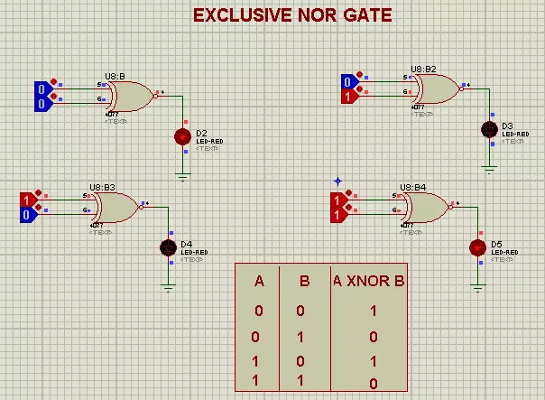
First of all, we will design the below circuit in Proteus:
Image
As you can see in the above figure, the first AND Gate is getting the inverted inputs and the second AND Gate is provided with simple inputs. Finally, the output of both AND gates is passed through the OR Gate and we got our XNOR output. I have placed an LED at the output to visualize it.
Applications of XNOR Gate
XOR Gate is used in many circuits as:- We use XOR Gate in digital circuits.
- It is used in error-detecting Circuits.
- XOR is also used in Arithmetic Circuits.
- Encryption Circuits is the application of XNOR Gate.
- The combinational circuit is made through XNOR Gate.
- XNOR is used in sequential Circuits.
- Circuit of Binary to Grey and vice versa.