Half Adder through XOR with AND Gate in Proteus ISIS


Hello Pupils! I welcome you to The Engineering Projects. I hope you are having a good day. In our previous lectures, we simulated almost all the DLD Logic Gates i.e. AND, OR, NOT, NOR, NAND, XOR and XNOR. I hope now you must have a complete understanding of the logic gates and their working.
Now, it's time to have a look at the reason for inventing these logic gates. These DLD logic gates are used to design different numerical modules i.e. adder, subtracter, multiplexer, de-multiplexer, encoder, decoder etc. These arithmetic modules are normally used in electronic products i.e. a simple microcontroller has numerous adders/subtractors for properly calling the registers' addresses.
So, from today onward, we are going to discuss these applications of logic gates one by one. Today, we will focus on the basic one i.e. Half Adder. First, we will understand its working and later will simulate it in Proteus.
Let's have a look at what we'll learn today.
- What is an Adder?
- What is Half Adder?
- Truth Table of Half Adder.
- Half Adder Simulation in Proteus.
- Advantages of Half Adder.
- Disadvantages of Half Adder.
Let's start the Learning.
What is Adder?
- In DLD, an Adder is a simple digital circuit, designed using logic gates and is used to add binary numbers(normally bits).
- Advance Adders can also add other number systems i.e. Binary Coded Decimal, HexaDecimal etc.
- There are two types of Adders, named:
- Half Adder
- Full Adder. (We will cover it in the upcoming lectures)
Now, let's have a look at the definition of Half Adder:
What is Half Adder?
- A Half Adder is a simple arithmetic electronic circuit, designed using logic gates to add two binary numbers.
- A Half Adder produces two Outputs of 1-Bit each. These outputs are the Sum and Carry of the added numbers.
- The numbers being added(i.e. inputs of Half Adder) are called augend and added.
- A simple Half Adder is shown in the below figure:

- We will understand the working of Half Adder in the next section but for now, we can see in the above figure, the Adder circuit has two inputs and 2 outputs.
- The first output is Sum Bit and the second one is Carry Bit.
- A simple Block Diagram of Half Adder is shown below:

Logical Circuit
In order to design a DLD Half Adder, we will need to use the following two logic gates:
- XOR Gate
- AND Gate
If we recall from our previous lectures on logic gates, the XOR Gate is used to provide the Sum of the Inputs, while the AND Gate provides the Carry of the Inputs. So, by combining these two gates, we can easily get both the Sum and the Carry.
Mathematically,
SUM = A XOR B
CARRY = A AND B
- Here's the Truth Table of XOR Gate:
| A | B | Z |
| 0 | 0 | 0 |
| 0 | 1 | 1 |
| 1 | 0 | 1 |
| 1 | 1 | 0 |
- The Truth Table of AND Gate is given below:
| A | B | Y |
| 0 | 0 | 0 |
| 0 | 1 | 0 |
| 1 | 0 | 0 |
| 1 | 1 | 1 |
Let's move towards the Practical implementation of Half Adder in Proteus ISIS.
Simulation of Half Adder in Proteus
To design the circuit of Half Adder, we need the following components:
Components Required:
- AND Gate.
- XOR Gate.
- Logic toggle.
- LED.
- Ground Terminal.
Circuit Diagram of Half Adder
- Select the first four components from the Proteus Library.
- Place the XOR Gate and AND gate in the Proteus Workspace.
- Connect the Logic Toggles on the Inputs of the XOR Gate.
- Join the inputs of AND Gate with the Inputs of XOR Gate.
- Connect the LEDs with the output Terminals of both Gates.
- Add the ground terminal with both LEDs.
- The below figure shows the Half Adder Circuit in all possible scenarios:

- Here's the Truth Table of Half Adder:
| Input | Output | ||
| A | B | Sum |
C0 |
| 0 | 0 | 0 | 0 |
| 0 | 1 | 1 | 0 |
| 1 | 0 | 0 | 0 |
| 1 | 1 | 1 | 1 |
Advantages of Half Adder
- Half Adders are simple in construction & easy to design.
- We can get a Half Subtractor simply by inverting the circuit.
Disadvantages of Half Adder
- There is no mechanism to use the carry in the next addition.
- Can perform very specific functions.
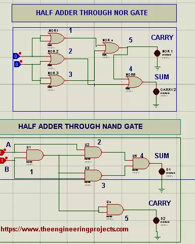
So, that was all for today. I hope you have enjoyed today's lecture. Today, we designed the Half Adder using AND and XOR gates. In the next lecture, we will design the Half Adder using Universal Gates i.e. NAND and NOR gates. Till then, take care. Have fun!!!