Half Subtractor in Proteus ISIS


Hey Pals! We hope you are doing Great. Today, we are going to design another application of DLD Logical Gates i.e. Half Subtractor. In our previous lectures, we covered Adders in detail, where we studied both Half Adders & Full Adders. Now its time to discuss its reciprocal i.e. Subtractors.
In this session, we'll seek the answers to the following topics:
- What is Half Subtractor?
- Working Principle of Half Subtractor.
- Truth-table of Half Subtractor.
- Simulation of Half Subtractor in Proteus using three Logic Gates.
- Designing of Half Subtractor with NOR gate.
So, let's get started:
What is Subtractor?
The functionality of Subtractors is exactly the opposite of Adders(we discussed in previous lectures) and defined as:
- A Subtractor is a simple DLD Electronic circuit, designed using logic gates and is used to subtract binary numbers from one another.
- A DLD Subtrator generates two outputs(1-bit each) called Difference Bit and Borrow Bit.
- There are two types of Subtractors available:
- Half Subtractor. (We are discussing today)
- Full Subtractor. (We will discuss in the next lecture)
Now, let's have a look at the Half Subtractor:
Half Subtractor
DLD Half subtractors(same as Half Adders) are designed using logic gates and are quite simple in construction. We can define Half Subtractor as:
- "Half Subtractors are simple digital logical circuits, used to subtract two binary numbers from each other and generate two outputs called Difference Bit and Borrow Bit.
- The Half Subtractor takes two Inputs A and B and performs the subtraction operation i.e. A - B, where A is called Minuend Bit and B is called Subtrahend Bit.
Working Principle of Half Subtractor
The Half Subtractor has a boolean circuit. It means it works only with the two digits i.e, 0 and 1. The 0 describes the LOW bit and vise versa. It take two bits through the input Terminals and calculate the whole system then shows us the result at the Output Terminals.Difference in Half Subtractor
The difference is obtained when we perform the minus operation with the second bit from the first bit. the calculator give us the output that is the remaining value of the 1st bit when we deduct the value of 2nd bit from it.Borrow in Half Subtractor
In the case, when the second bit is higher then the 1st bit, the subtractor borrows a bit from the circuit. this is an essential operation because without this, subtraction can not be proceed further.Half Subtractor Truth Table
In binary digit difference, the subtraction of 0 with 0 produces the difference 0 and the borrow 0. when the Value is change to A=0 and B=1 then the circuit borrows a bit and both the bits becomes 1 hence we get Difference=1 and borrow=1. When the inputs are A=1 and B=0 then we simply get the value Difference=1 and Borrow=0. At the same token, when A=1, B=1 then the result we get is Difference=0, Borrow=0. Using all these concepts we get the Truth Table as:| A | B | Difference | Borrow |
| 0 | 0 | 0 | 0 |
| 0 | 1 | 1 | 1 |
| 1 | 0 | 1 | 0 |
| 1 | 1 | 0 | 0 |
- Half Subtractor using three Logic Gates.
- Half Subtractor using only NAND Gate.
DID YOU KNOW???????????
Half subtractors are used to limit the force of audio or Radio signals.
Half Subtractor Using three Logic Gates
In this type of formation we use three Logic Gate given below:- XOR Gate
- NOT Gate
- NAND Gate
| A | B | A XOR B |
| 0 | 0 | 0 |
| 0 | 1 | 1 |
| 1 | 0 | 1 |
| 1 | 1 | 0 |
Proteus simulation for Half Subtractor sing Three Gates
Material Required
- XOR Gate
- AND Gate
- NOT Gate
- LED-RED
- Ground Terminal
- Connecting Wires
DID YOU KNOW?????????????
Arithmatic Logic Unit uses the Half Subtractor for the functioning.
- Begin you Proteus Software.
- Choose first four Components from Pick Library through "P" Button.
- Arrange the Logic Gates one after the other one the working area just as shown in the image:

- Arrange two Logic Toggles Just in front of the XOR Gate.
- Get one LED and Set it Just after the XOR Gate.
- Repeat the step with the with AND Gate.
- Go to Terminal Mode>Ground attach a ground Terminal with each LED.
DID YOU KNOW?????????????????
One can also use the Logic Probe to Get the output instead of LED.
- Connect all the Components through wires in accordance with the image below:

- Change the values at the Input one after the other and notice the output.
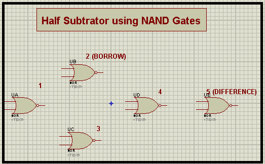
Half Subtrator using NOR Gate
Sometimes, you need to make the Circuit as simple as you can. Or you can only use one gate then it is also possible to make the whole circuit using just one gate i.e, NOR Gate. when we look at the definition, it says A NOR Gate is the one that shows the output HIGH only when the Input are LOW. So, one can use the NOR Gate in different ways just by using the connection in a specific way. Let's see how can we do this.Proteus Simulation of Half Subtractor using NOR Gate
Material Required- NOR Gate
- Logic Toggle
- LED-RED
- Ground Terminal
- Connecting Wire
- Choose the Required Material.
- Arrange the NOR Gates with respect to the image given next:

- Set Logic Toggles in front of Gate 1.
- Attach the LED's with the output of Gate two and 5.
- Ground each LED.
- Join all the devices through Connecting wires with the help of this image:

×
![]()