2-bit Full Subtractor in Proteus ISIS


- What are 2 bit Full Subtractors?
- How can we design the Truth Table of 2 bit Full Subtractor?
- How can we implement the 2 bit Full Subtractor in Proteus ISIS?
2 bit Full Subtractors
A full Subtractor works really well in the processor. We’ll talk about it function but before that have a look at its definition:- 2 bit Full Subtractor is a Combinational Logic that contain three Inputs and Two outputs and perform the function of Subtraction with two bits.
- Minuend: The 1st input is called the Minuend used to take the bit from which the 2nd value will be Subtracted.
- Subtrahend: It is called the 2nd input that is subtracted from Minuend.
- Borrow in: It is the third input that is use to take the value of the Previous borrow and we’ll denote it as B(in) here.
- Borrow Out: The Borrow out is symbolized as B(out) and it the resultant borrow that the output Terminal shows.
- Difference: This is the main result that was the concern of the experiment and its value totally depends upon the binary subtraction rules.
DID YOU KNOW?????????????????
There is another circuit called Half Subtractor that is used for the subtraction of bits but the foremost disadvantage of that circuit was its inability to work with the borrow taken in the previous calculation and the designers worked for another better Subtractors.
Truth Table of 2-bit Full Subtractor
If you know about the Concept of binary subtraction, you can use your knowledge to generate a Truth Table of 2 bit Full Subtractor so that one can design a feasible Circuit of 2 bit Full Subtractor. The Table contain all the records that can be possible for our experiment and its result into the bargain. Thus the Truth Table for the Full Subtractor is shows as:| Minuend | Subtrahend | B(in) | Difference | B(out) |
| 0 | 0 | 0 | 0 | 1 |
| 0 | 0 | 1 | 1 | 1 |
| 0 | 1 | 0 | 1 | 1 |
| 0 | 1 | 1 | 0 | 1 |
| 1 | 0 | 0 | 1 | 0 |
| 1 | 0 | 1 | 0 | 0 |
| 1 | 1 | 0 | 0 | 0 |
| 1 | 1 | 1 | 1 | 1 |
Working Mechanism of 2 bit Full Subtractor
When we observe the Circuit of 2 bit Full Subtractor, we found that it is combination of two circuits of Half subtractors and the output of each circuit is then fed into an OR Gate through which we get the output of borrow. We have two types of outputs in the 2 bit Full Subtractor:- Difference
- Borrow
Let's have a look at the procedure of calculation of both.DID YOU KNOW?????????????????
The Full Subtractor is the one of the most fundamental Logic circuits of that are used for two bit subtraction in many computing system.
Difference
The binary subtraction is similar to the decimal subtraction but it works with only two digits called 0 and 1 instead of 1 to 10 in the decimal. When we examine the answer of the bit difference while using a Truth Table in the Half Subtractor circuit, we found that it is identical to the XOR Gate. Therefore we use a XOR Gate for the Difference that is introduced as:The type of Logic Circuit that gives the output HIGH only when both its inputs have inverse value to each other and vise versa.Thus the truth table for the XOR Gate is given as:
| A | B | A XOR B |
| 0 | 0 | 0 |
| 0 | 1 | 1 |
| 1 | 0 | 1 |
| 1 | 1 | 0 |
DID YOU KNOW???????????????
The Application of the Full Subtractor is found in the ALU of computer where they are responsible for the Graphic application to decrease the difficulty in the CPU and GPU.
Borrow
Many times, the situation arrives when the Minuend<Subtrahend and in this way, the circuit need to borrow a bit from the bit presented just after it. The Full Subtractor do this through the AND Gate that contain a NOT Gate at its one end. For full Subtractor, this arrangement is again fed into the duplicated circuit and the both the outputs of this AND Gate is fed into the OR Gate that gives us the Borrow(out).2 bit Full Subtractor in Proteus ISIS
- Start up your Proteus Software.
- Collect the following devices from the Pick Library.
Devices Required
- XOR Gate
- AND Gate
- OR Gate
- Logic Toggle
- LED-Red
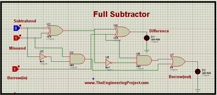
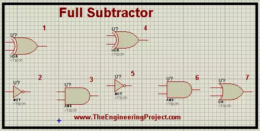
- Arrange the XOR Gate, AND Gate and NOT Gate at the working area according to the arrangement given below:
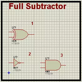
- This will form a Half Subtractor. Select the devices through a square selection area.
- Copy the whole arrangement through left click>copy to clip board.
- Paste the arrangement in the side of the circuit.
- Add an OR gate at the right side of the system. The screen should look like the image given below:
- Add three Logic Toggles at the left most side of the arrangement.
- Connect the Whole circuit through connecting wires by matching the circuit with the following image:
- This is the Full Subtractor circuit. Change the values of the Probes according to the Truth Table and record your observation.
×
![]()