Traffic Light Simulation with D Flip Flop in Proteus


- What are the Traffic Lights using D Flip Flop?
- What is the role of D Flip Flop?
- How does the circuit of D Flip Flop work in the Traffic Lights?
- How can you simulate the circuit of Traffic Lights with D Flip Flop in Proteus?
Traffic Lights with D Flip Flop
Who is not aware of the traffic lights? we all observe and use the Traffic lights on the road every day. But for the sake of the concepts, let's see the traffic lights technically."The Traffic Lights are the signaling devices that has an electronic circuit designed to control the flow of traffic at the roads by a specialized pattern of lights."These traffic lights are positioned at road intersections ad pedestrian crossing and other positions where the traffic flow has to maintain.
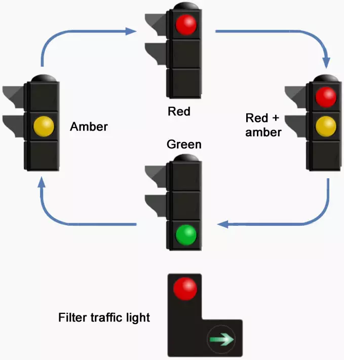
- Red
- Amber
- Green
Role of D Flip Flop in Traffic Lights
Have you ever thought about how does the traffic light blink at a specific time? We all follow the Traffic lights but today we'll learn that what does traffic light follows. The D Flip Flops are the logical circuits and we define the D Flip Flop as:"The D Flip Flops a dual input is Flip Flop circuit that is designed to have the input at its D Terminal, regulates the signal with the clock edge pulses and shows the output at its two output terminals."In the Traffic Lights, we use two D Flip Flops that are responsible for the switching of the lights in on or off conditions. The D Flip Flop is the combination of the S and R Flip Flops with an inverter with one terminal. but for simplicity, we'll use the Integrated Circuit of D Flip Flop. Hence our circuit has only four components and we get a clean, easy and useful circuit that works automatically. The input Terminals are called CLK and D terminals whereas output terminals are denoted by Q and Q'. The Truth Table for the D Flip Flop is given next:
| Inputs | Output | ||
| CLK | D | Q | Q’ |
| 0 | X | No Change | |
| 1 | 0 | 0 | 1 |
| 1 | 1 | 1 | 0 |
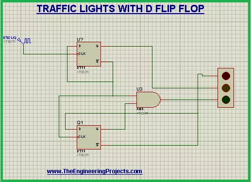
Working of Traffic Lights circuit with D Flip Flop
The working of the Traffic Light starts with the change in the pulse of the clock.- The Q' output of the D Flip Flop 2 gives the power to the Red Light of the Traffic Light.
- When the clock is low, there is no change in the Q' terminal of the 1st Flip Flop then the Amber light is off.
- With the clock pulses, the Amber light of the Traffic Light turns on.
- When the clock is high, we get the output inverse of the D Flip Flop.
- The output Q of the D Flip Flop1 and the Q' of the D Flip Flop 2 is fed into AND Gate.
- We know the AND Gate is HIGH only when both of its terminals are HIGH.
- This output of the AND Gate is connected with the Green Light of the Traffic Light.
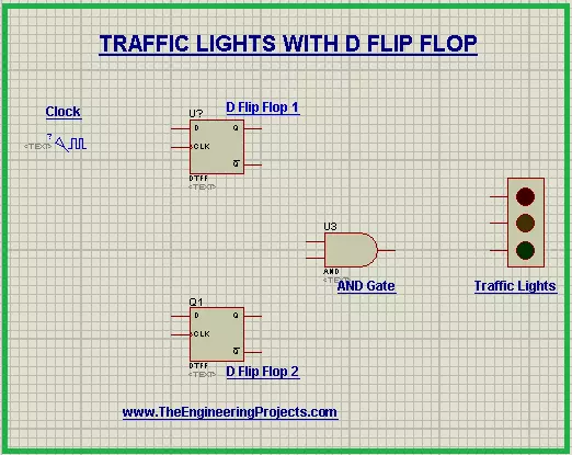
Circuit Simulation of Traffic Lights in Proteus ISIS
For the simulation of Traffic Light in Proteus, simply follow the easy steps coming next.Devices required for the Traffic Lights
- D Flip Flop - DTFF
- Traffic Lights
- AND Gate
- Clock pulses - DClock
- Connecting wires
- Power up your Proteus software.
- Click the "P" button.
- Write the names of 1st three devices given above one by one and choose them.
- Get D Flip Flop twice, And Gate and Traffic Lights from the pick library and arrange them on the working area.
- Go to Generation mode(from the sidebar) >DClock and set it just on left side of the 1st D Flip Flop.
- Connect all the components with the help of connecting wires.
- Connect the Traffic Light's red light with the output of 1st D Flip Flop, the amber light with the D Flip Flop 2 and the green light with the output of AND Gate.
- Pop the play button.
×
![]()