


What is 555 Timer?


In today's tutorial i am going to explain, what's hidden inside this 555 timer IC and what is 555 timer. A 555 timer is a much compatible electronic device and the biggest feature of this IC is that it able to work on both analogue and digital techniques. Now if we simply consider the output of the 555 timer then, at any particular time, this timer has only 1 definite state. Which means at any time, it will be either ON or OFF. It is not possible that its output is ON and OFF simultaneously. A new invention of 555 timer has also been discovered which is named as 556 timer. 556 is in fact a Dual version of 555 timer and it contains 2 555 timers in a single IC. 556 is a 14 pin IC. Now you will think that 555 timer is a pin IC and as i said that 556 contains two 555 timers then, it should have 16 pins. The answer to this question is that, when two 555 timers are connected to each other then the VCC and GND of both ICs is made common so, we have 14 pins instead of 16. Now let's move towards the basic theme of our tutorial. In this tutorial i will be explain the steps, the pin configuration of 555 timer, It's different modes and project applications.
Internal Design of 555 Timer
Before going into details of what is 555 timer, let's first come to the internal design of a 555 timer. The outer shape of the 555 timer may look like very simple but there is a complex mechanism hidden inside that small IC. A 555 timer contains 25 transistors, 15 resistors and 2 diodes, which are connected to each other in a very complex manner. An interesting thing to know here is that all these components are embedded on a single small silicon chip. Some other series of 555 timers are also available in market like NE555 timer, which we commonly use in our engineering or electronic projects. And the second series is SE555. SE555 series was designed for military purposes. These operating temperature ranges of both NE555 ans SE555 are given below as:
- NE555 is mostly used for basic level projects and such high level accuracy is not demanded in it so it is capable to operate from 0 ~ 70 degree Celsius.
- SE555 was designed for military applications and it is used in those projects where high precision is required. The operating temperature of this IC is -55 ~ +125 degree Celsius.
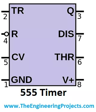
Pin configuration of 555 Timer
Let's have a look at pin configuration to know what is 555 timer. As I described earlier that 555 timer has total 8 pins. As i described that 555 timer is a multipurpose IC and it is capable to perform variable function. So through some proper arrangement of connections, we can made this IC to do different tasks. Now i will explain the every pin no. and its purpose so that we know the answer to our main question what is 555 Timer ??? :)
- The pin designated as pin#1 is GND pin. This pin is used to provide reference voltage or ground to 555 timer.
- The pin designated as pin#2 is TR pin. It is used for triggering of 555 timer. The operating voltages of 555 timer is 4.5V ~ 15V. When the operating voltages exceeds 5V then, the 555 timer triggers and it generated output or we can say that now it has crossed that limit above which it will generate output.
- The pin designated as pin#3 is the output pin of 555 timer. Through this pin, the output of 555 timer goes to the external circuit. The output depends on the purpose for which you are using 555 timer. For example if you are using your 555 timer to generate PWM then its output will vary. Sometimes it will go High and some time it will go Low.
- The pin designated as pin#4 is Reset pin of 555 timer. If you look closely on the first feature image of the tutorial then, you yourself will understand that it is a NOT function. Which means that in order to reset the 555 timer you will have to give '0' at that pin and after the compliment it will become High and 555 timer will 'Reset' .
- The pin#5 of 555 is 'CTRL' pin. It is in fact a control pin of 555 timer. This pin gives us the direct access to the internal voltage divider of the 555 timer, which is fabricated inside that small silicon chip. We can divide the voltages according to our output requirements.
- The pin#6 is named as 'THR' pin of the 555 timer. For the supply voltages, 555 timer has kept a reference value for them. For example when the supply voltages exceeds 5 volts then, the this pin becomes activated and the 555 timer starts to generate output or it sends data to its output pins.
- Pin#7 is named as 'DIS' of the 555 timer. This pin is in fact the discharge pin of 555 timer and used to discharge the capacitors between intervals. This pin has the biggest advantage when, we are generating PWM through 555 timer.
- The last pin is pin#8 and it is designated as 'VCC' . This is the supply pin of 555 timer. Source is connected at this pin and as i have already explained that the supply voltages range for 555 timer is 4.5V ~ 15V, but generally it triggers above 5 volts.
Modes of Operation - What is 555 Timer ???
In order to know what is 555 Timer, we should have a look at its modes of operation. 555 timer has 3 major modes of operations. All these modes have there own applications and advantages. All the 3 modes are explained in below:
Astable Mode of 555 timer:
From the name of this mode 'astable mode', you can understand that, in this mode, we don't have any stable output of 555 timer. While operating in this mode, the output will be continuously fluctuating and we will be obtaining a square wave form on the output pin of the 555 timer. To operate the 555 timer in Astable mode, you will have to draw the following circuit, which is shown in the image below:
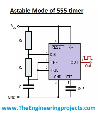
- Astable mode is also used to flash lamps and leds. A very similar project named as Sequential LED blinking using 555 timer has also been uploaded by our team. In that project 555 timer was again being used in astable mode.
Monostable Mode of 555 timer:
In this mode of operation the 555 timer gives only one output pulse in addition to the intentional trigger input. For example if you will press the button then, 555 timer will produce a output pulse and its length remains constant until you again press the button and the 555 timer will generate another pulse. The circuit to use 555 timer in monostable mode is shown in the image given below:
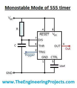
- Monostable mode of 555 timer has wast application. In this state it is used as a timer, touch switches.
- The biggest example of this mode is to generate PWM. If you recall one of my previous tutorial which was Angle control of servo motor using 555 timer, then at that stage we were using a 555 timer to generate a PWM and through this PWM, we were controlling the angle of micro servo motor.
- This mode is also used for capacitive measurement and also for missing pulse detection.
Bistable Mode of 555 timer:
The third and the last mode of operation of 555 timer is to use it in bistable mode. This thing is understood from its name 'Bistable' which means this circuit will have 2 stable states, which we are going to control. The circuit diagram to operate a 555 timer in bistable state is shown in the image given below:
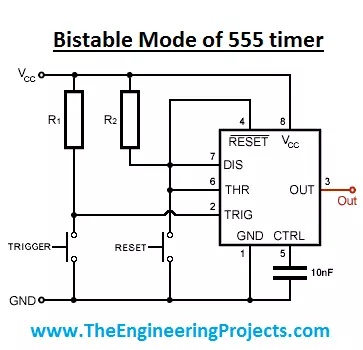
- The above shown circuit is of bistable mode of 555 timer.
- As you can see in the above figure, we have 2 push buttons. One is connected to 'THR' pin and the other is connected to 'TRIG' pin of 555 timer.
- When we will press the 'TRIG' button, which means that we have connected the trigger state to ground and its state has become LOW. By doing that the output of 555 timer will become High.
- On the other hand, when i will press the 'RESET' button then 'THR' pin of 555 timer will be grounded and the output of 555 timer will become LOW.
- In this way we have made the 555 timer to work in 2 different states and that's why it is called Bistable mode of operation of 555 timer.


