Hi Friends! I welcome you on board. Thank you for clicking this read. In this post today, I’ll detail the Introduction to IRF740.
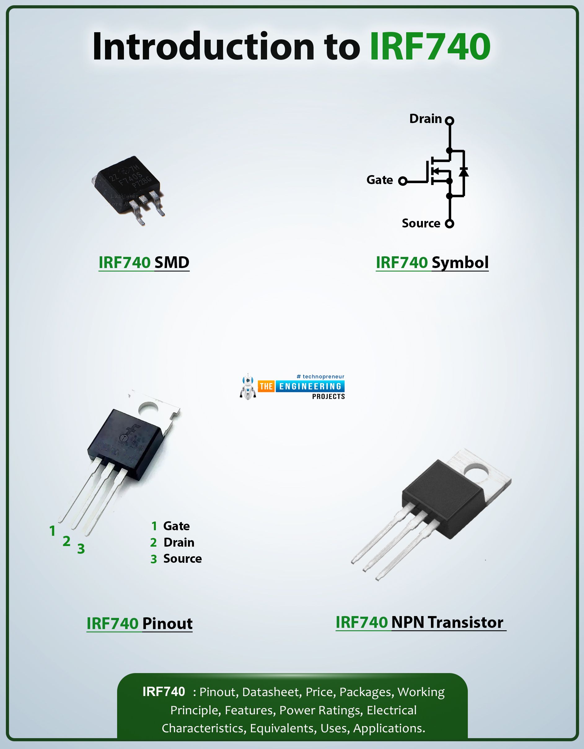
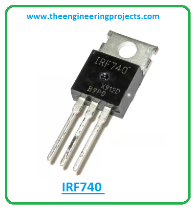
The IRF740 is an N-channel power MOSFET used for extremely fast switching applications. It comes with a power dissipation of around 125W and can support loads up to 400V. The maximum drain current of this device is 10A and the drain-source capacitance is 1450pF.
I suggest you read this post till the end as I’ll describe the complete Introduction to IRF740 covering datasheet, pinout, features, and applications.
Introduction to IRF740
- The IRF740 is an N-channel MOSFET that comes with 125W power dissipation. This is the power device that dissipates during the working of this component.
- This device is mainly used for fast switching applications and comes with ultra-low on-resistance of 0.55 Ohms which is the resistance between drain and source terminals.
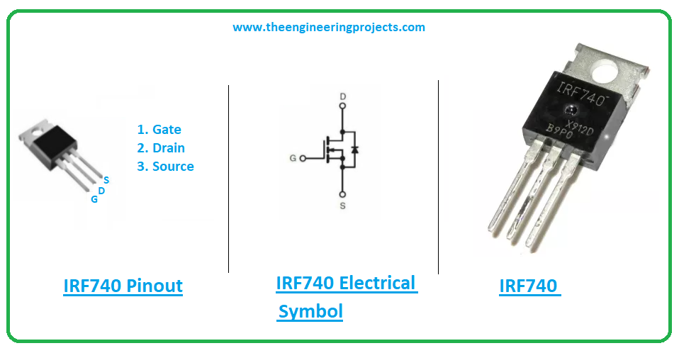
- The IRF740 contains three terminals named source, drain, and gate. Sometimes it is termed as a four-pin device when the body is also considered as its terminal.

- The gate terminal is located between the source and drain terminals and is the area used for biasing of the device. While the drain terminal is the location from where electrons leave the channel and the source terminal is the location from where electrons enter the channel.

- The MOSFETs are mainly categorized into two main types named N-channel MOSFET and P-channel MOSFET. This device IRF740 belongs to the N-channel MOSFET where electrons are responsible for the current flow inside the device as opposed to P-channel MOSFETs where holes are the charge carriers responsible for conductance inside the device.
- It is important to note that the movement of the electrons is better than the movement of holes inside the MOSFET. The reason N-channel MOSFETs are preferred over P-channel MOSFETs in a range of applications.
- The MOSFET operates in two modes i.e. depletion mode and enhancement mode.
- The nature of electrons is opposite in both these modes in N-channel MOSFETs. During the enhancement mode when there is no voltage, there will be no current across the channel. However, when voltage is applied across the gate terminal, it increases the movement of electrons and thus increases the conductance.
- On the other hand, during depletion mode, when there is no voltage applied across the gate terminal, there is current across the channel. However, when the voltage is applied across the gate terminal, it will decrease the movement of electrons and hence decrease the channel conductivity.

IRF740 Datasheet
Before you apply this device to your electrical project, it’s wise to go through the datasheet of the device that features the main characteristics of the component, helping you better understand the absolute maximum ratings of this device. Click the link below to download the datasheet of IRF740.IRF740 Pinout
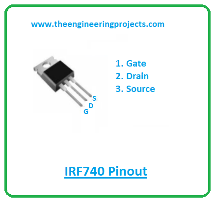
The following figure shows the pinout diagram of IRF740.
| Pin Description of IRF740 | ||||
|---|---|---|---|---|
| Pin No. | Pin Description | Pin Name | ||
| 1 | Used for biasing the device | Gate | ||
| 2 | Electrons leave the channel through this terminal | Drain | ||
| 3 | Electrons enter the channel through this terminal | Source | ||
IRF740 Features
The following are the main features of IRF740.- Type = N-Channel Power MOSFET
- Category = IRF series
- Capable of fast switching
- Power Dissipation = 125W
- Continuous Drain Current (ID) = 10A
- Gate threshold voltage (VGS-th) = 10V (limit = ±20V)
- Drain to Source Breakdown Voltage = 400V
- Drain Source Resistance (RDS) = 0.55 Ohms
- Rise time is 27ns and fall time is 24nS
- Junction temperature = 150C
- Maximum Drain current = 10A
- Drain-source capacitance = 1450pF
- Available package = TO-220
IRF740 Applications
The IRF740 is employed in the following applications.- Used in USP
- Employed in instrumentation projects
- Used in switching applications
- Used in embedded projects
- Employed in Inverters
That’s all for today. Hope you’ve got a clear idea about this device IRF740. If you have any questions, you can pop your comment in the section below. I’m ready and happy to help you the best way I can. Feel free to share your valuable feedback and suggestions around the content we share so we keep sharing quality content tailored to your exact needs and requirements. Thank you for reading the article.


 Electronic Components
 jameswilson
 0 Comments


 2.3k
2.3k
 953
953
 921
921
 2.1K
2.1K

