ESP32 Web Server in Access Point (AP) Mode


ESP32 can be operated as an access point (AP) or a Wi-Fi station (STA mode). So, in this tutorial, we will create an ESP32 web server in access point (AP) mode. Here's the video demonstration of ESP32 WebServer in Access Point Mode:
As I mentioned above, in our 2nd tutorial, we already discussed the basics of the ESP32 web server. So, in this tutorial, we will only discuss how to create the ESP32 in access point mode.
For detailed information about the basics of the ESP32 web server and how client-server communication takes place, follow our previous tutorial (i.e., Create a Web Server with ESP32).
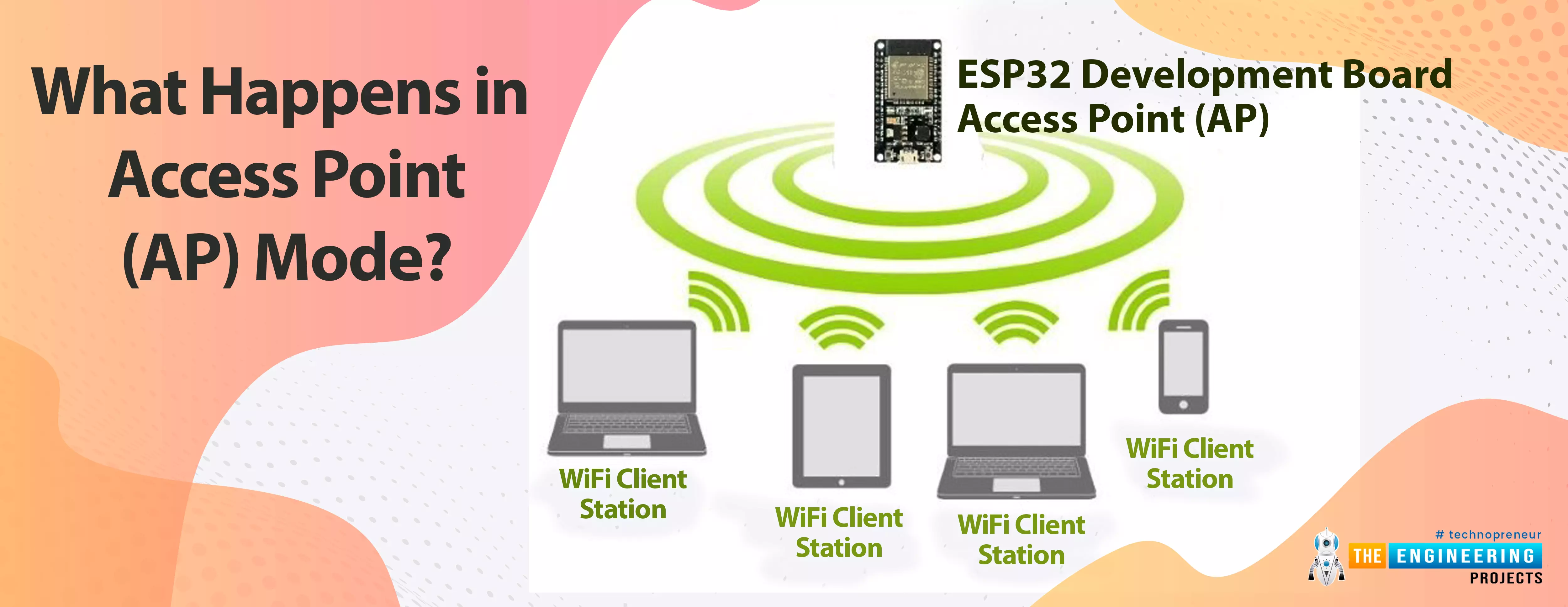
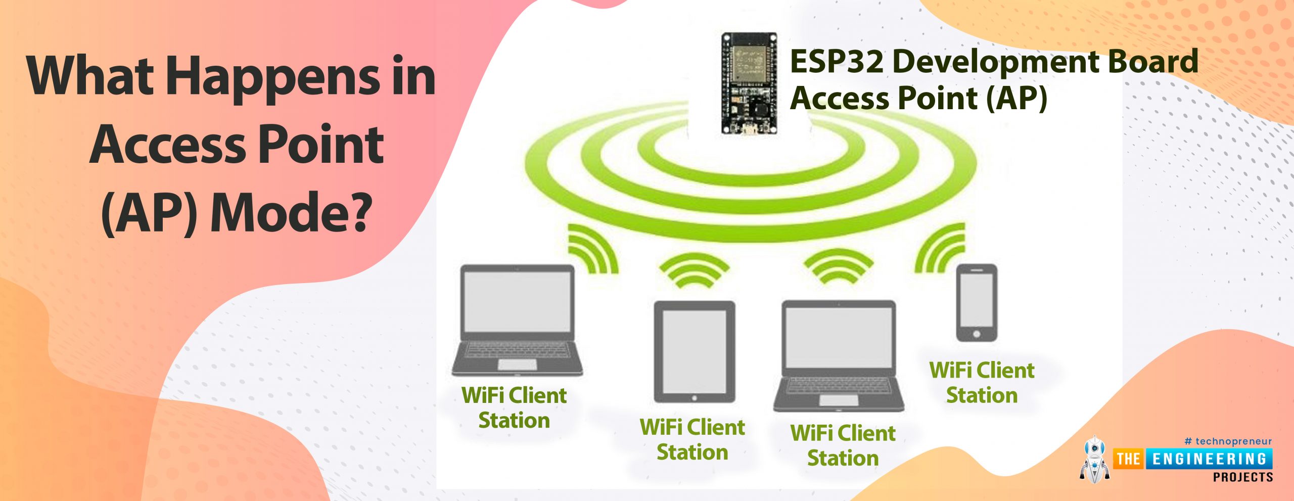
What happens in Access Point (AP) mode?
In Access Point Mode the ESP32 creates its own wireless Wi-Fi network in this mode, similar to the one provided by your existing router. In access point mode, we don't need to connect the ESP2 to a Wi-Fi network. In the Wi-Fi network it creates, the ESP32 Wi-Fi board can connect up to 5 devices.
Fig 1 ESP32 as an Access Point
So, in access point mode, nearby Wi-Fi devices such as mobile phones, laptops, or a secondary ESP32 module acting as a station can connect directly to the AP (ESP32 module) without the need for an external Wi-Fi router.
On the other hand, in Station mode, the ESP32 wi-fi module connects to your Wi-Fi network through a router. The router acts as a conduit for communication between the web client and the ESP32. The Wi-Fi router provides the IP address. This IP address can be used by web clients to connect to the Web server on a local network.
To know about how to set up/operate Arduino IDE for ESP32 compilation, follow our first tutorial i.e., Introduction to ESP32 programming series.
ESP32 Web Server in Access Point (AP) Mode
Here we are using an inbuilt example from Arduino IDE(ESP32). You can modify the example code as per your requirements or can write your own code.
- To find the Wi-Fi Access Point example in Arduino IDE :
- Click on File from the top menu bar.
- Place the mouse cursor on the example option from the list.
- Look for the WiFi option.
- There you will find the WiFiAccessPoint option, click on that and compile the program.
A screenshot is attached below to help you find the example code in Arduino IDE.
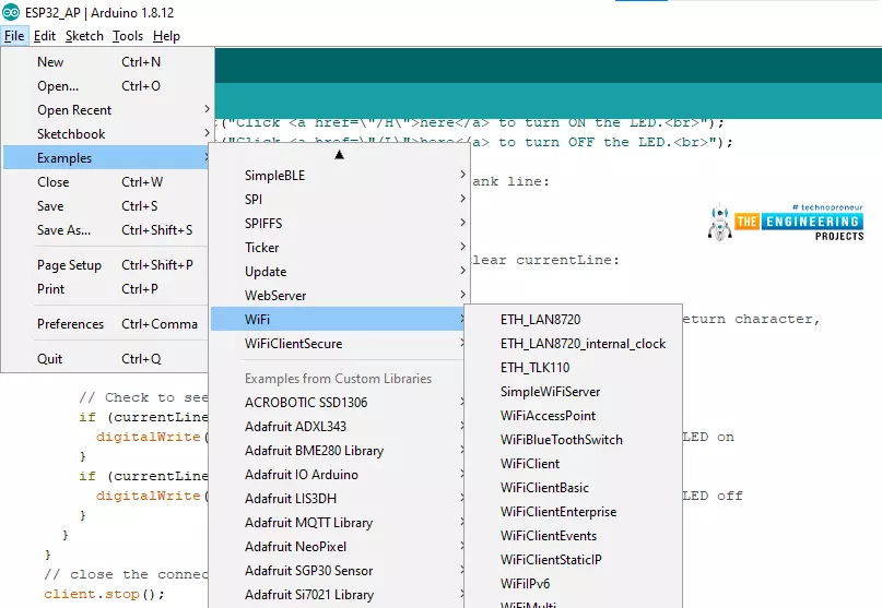
Fig 2 Wi-Fi access point example
The first task while writing the WiFi code is to add the required wifi header files or libraries in the code.
Here we are adding three libraries.
- WiFi.h: This header file contains all the functions related to Wi-Fi activities like enabling the Wi_Fi, connecting to a wi-fi network etc.
- WiFiClient.h: This header file is used to create a client that can connect with a specific IP address.
- WiFiAP.h: This header file is used to configure and manage ESP32’s wifi module in Access Point (AP) mode.
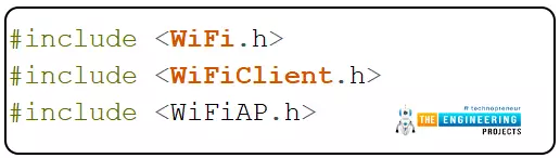
Fig 3: Libraries
Define the LED pin or a GPIO (for peripheral interface) which we going to control through web server. Here we are using the inbuilt LED which is internally connected with GPIO2

Give a name (SSID) to the ESP32 Access Point and set the password for security purpose ( if you wish to).
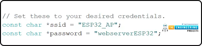
While creating a web server we also need to assign a port and usually port 80 is used for local web server.

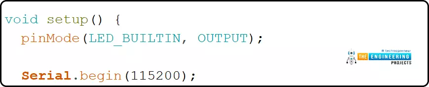
Arduino Setup() function
Inside the setup function, the LED pin is initialized as an output one and then initialized the serial monitor with a baud rate of 115200.
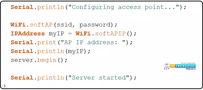
The next task is to configure the ESP32 Wi-Fi module in access point mode. For that, here we are calling a function called WiFi.softAP. Where we are passing two parameters, ssid and password, respectively.
After configuring the AP mode, we need to fetch the IP address of the access point by calling the WiFi.softAPIP() function and printing it on the serial monitor.
Then, after fetching the IP address, we will start the server using the server. perform.
Arduino Loop() function
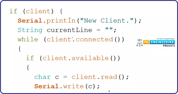
After configuring the Access Point mode and initializing the server, the server will next wait for the station or client connection, which can be a mobile phone, a laptop, or another ESP32 board configured in STA mode.

Once the connection is established between the access point and the client device, the access point will wait for the data input.
A string type variable called currentLine has been defined to hold the incoming data from the client.
If there is a byte to be read from the client, then it will be stored inside the char type variable c.
HTTP header always starts with a response code e.g.: HTTP/1.1 200 ok
An HTML page will be created on the client’s browser, from where the client device can control (ON/OFF) the LED.
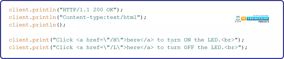
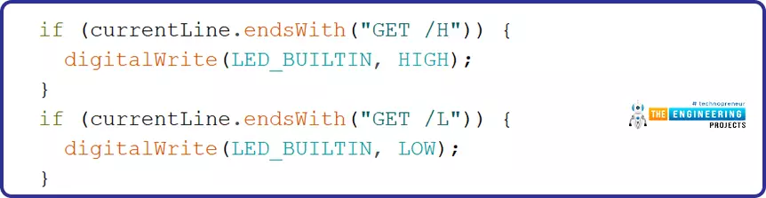
Different URLs will be created to turn ON and OFF the LED depending upon the HTML input received from the client device i.e., H (to turn ON the LED) and L ( to turn OFF the LED).
Client.stop() function is responsible for closing the connection between Access Point and client or station device.
Note: If you need any guidance regarding how to upload or compile a code for the ESP32 module in Arduino IDE, follow our first tutorial on the ESP32 programming series.
Testing ESP32 web server with hardware in Access Point with Arduino IDE
Here we are going to control the ESP32’s inbuilt LED through an ESP32 web server (AP mode).
We will connect our station or client device through Wi-Fi to the ESP32 module, which (ESP32) is currently acting as an access point (AP).
To establish the connection go to your mobile phone’s Wi-Fi setting.
The Access Point is advertising itself with a pre-defined SSID so that the station devices or clients can find the AP device and can communicate with each other.
If you find a wi-fi device (AP) named ESP32_AP (or as per your SSID) connect to that after entering the assigned password.
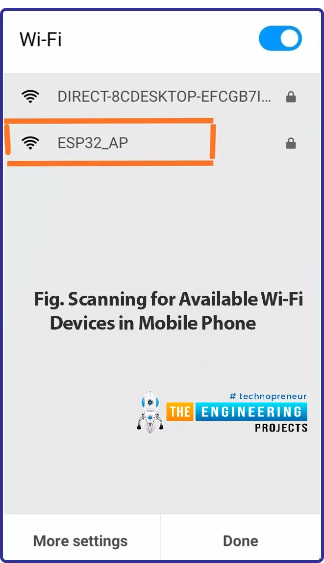
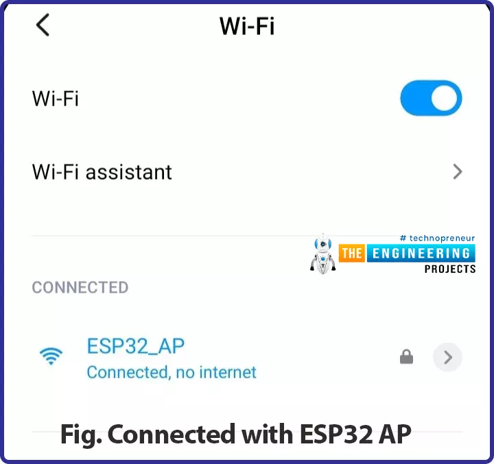
Fig. Connected with ESP32 AP
As we are using the inbuilt LED, no external components are required.
After connecting to the access point, you can find the IP address of the AP device printed on the Serial Monitor. As shown in the image below:
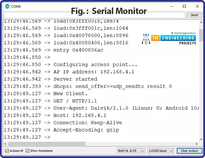
Fig.: Serial Monitor
Enter the IP address in the browser. Now you can turn the LED ON or OFF using the web page as shown in the images below.
A web page with URL 192.168.4.1/H will be displayed on the browser when LED is turned ON
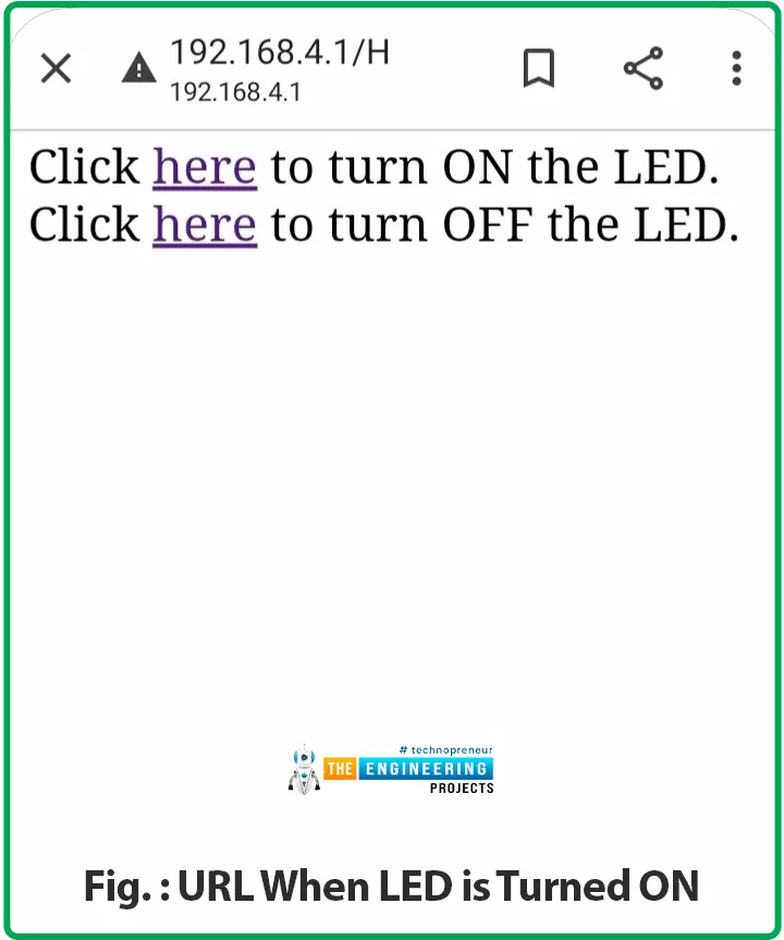
Fig.: URL when LED is turned ON
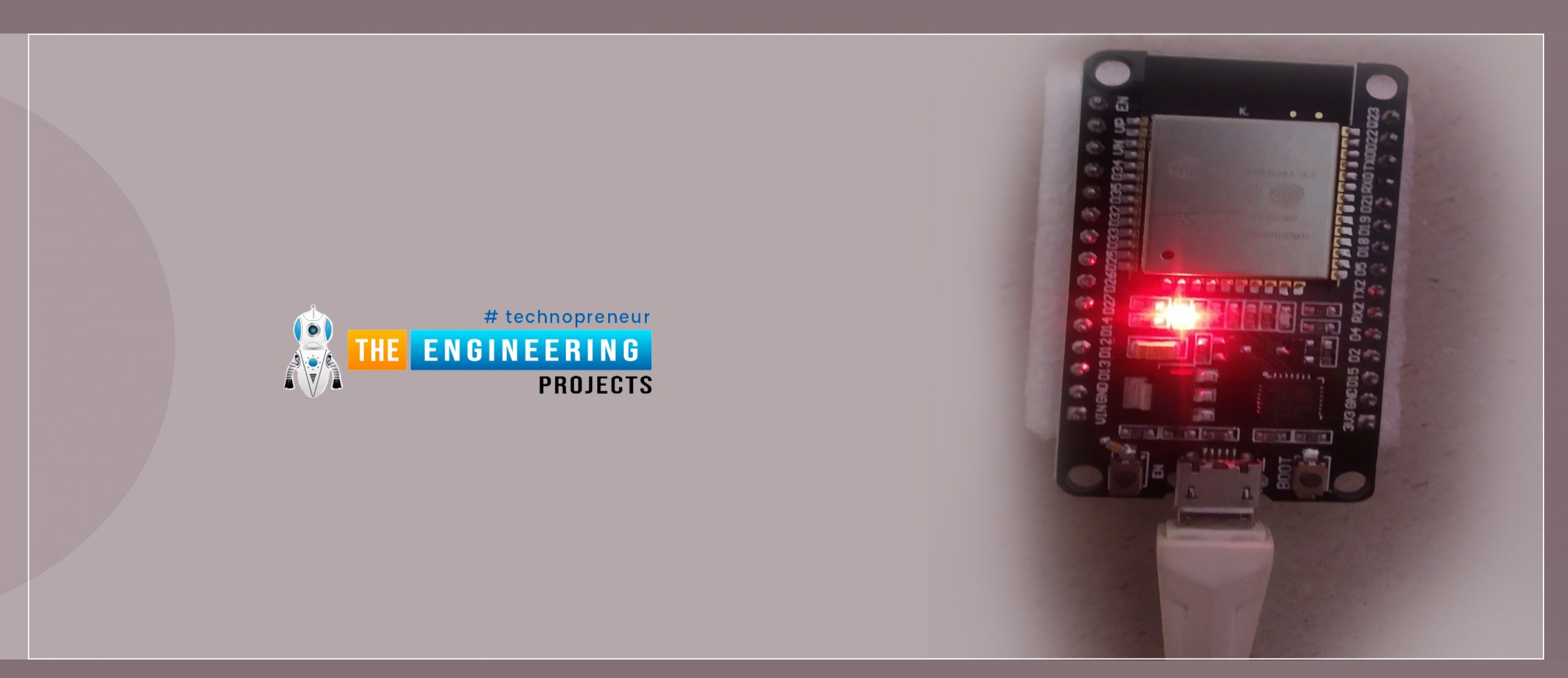
LED is blue color represents the inbuilt LED which is connected to GPIO_2.

Fig.: ESP32 LED ON
Another web page with URL 192.168.4.1/L will be created when the AP will receive the input to turn OFF the inbuilt LED. As shown in the image below:
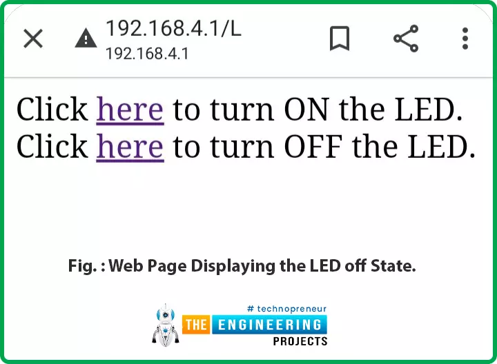
Fig.: Web page displaying the LED off state.
This concludes today’s tutorial. We hope you find it helpful.
In our next tutorial, we will discuss another ESP32 feature that is BLE (Bluetooth low energy).