Hello friends, I hope you all are doing great. Today, I am going to share the DFRobot FireBeetle 2 ESP32-E Library for Proteus. The FireBeetle 2 is a small black ESP32 board built for battery projects: it has a Li-ion connector with a charger, a very low sleep current, an RGB LED, a user button and a socket for a small display. With this library it runs your ESP32 Arduino sketch in Proteus 8.5, with all of those LEDs and buttons working, and joins our virtual Wi-Fi network.
FireBeetle 2 ESP32-E Library for Proteus
Latest version: V1.0 (November 2026, this tutorial)
Other ESP32 boards and modules: ESP32 DevKit V1 · ESP32-DevKitC V4 · ESP32-S3 DevKitC-1 · ESP32-C3 SuperMini · ESP32-C6 DevKitC-1 · TTGO T-Display · T-Display S3 · XIAO ESP32-C3 · XIAO ESP32-S3 · ESP32 Feather V2 · QT Py ESP32-S3 · ESP32-C5 DevKitC-1 · Olimex ESP32-POE · T-Call SIM800L · T-SIM7600 · T-Beam Supreme · M5StickC PLUS2 · ESP32-2432S028 CYD · M5Stack AtomS3 · M5Stack Core2 · LilyGO T-Deck · LOLIN S2 Mini · Heltec WiFi LoRa 32 V3 · LilyGO T-Beam · ESP32-CAM · ESP32-WROOM-32 · AirLift WiFi Shield · AirLift ESP32 Breakout · WT32-ETH01
Light sensors: LDR · BH1750 · TCS34725
Helping Tools
- Laptop WiFi Monitor: a laptop on the Wi-Fi of your design: a browser, a TCP / UDP terminal and ping
- Mobile WiFi Monitor: a smartphone that opens the pages of your board and sends it commands
- Serial Monitor Advance: a serial terminal window for the UART of your board
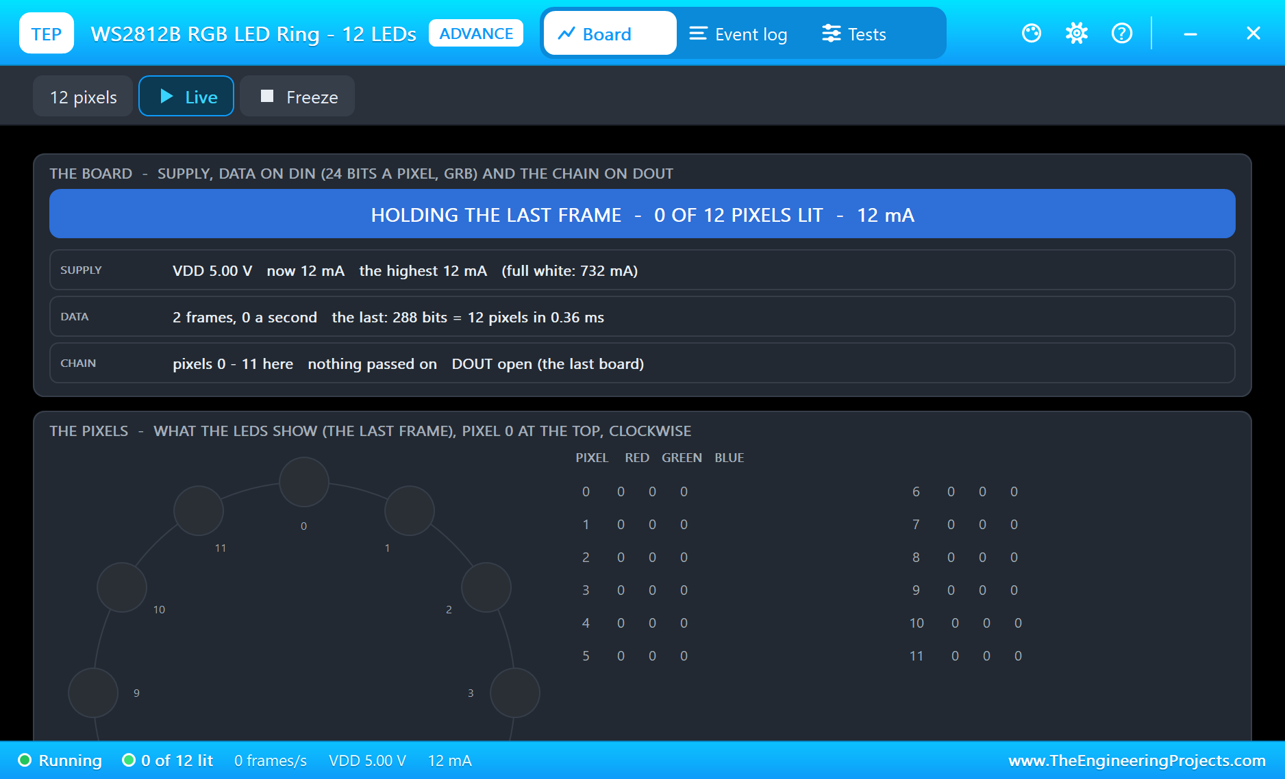
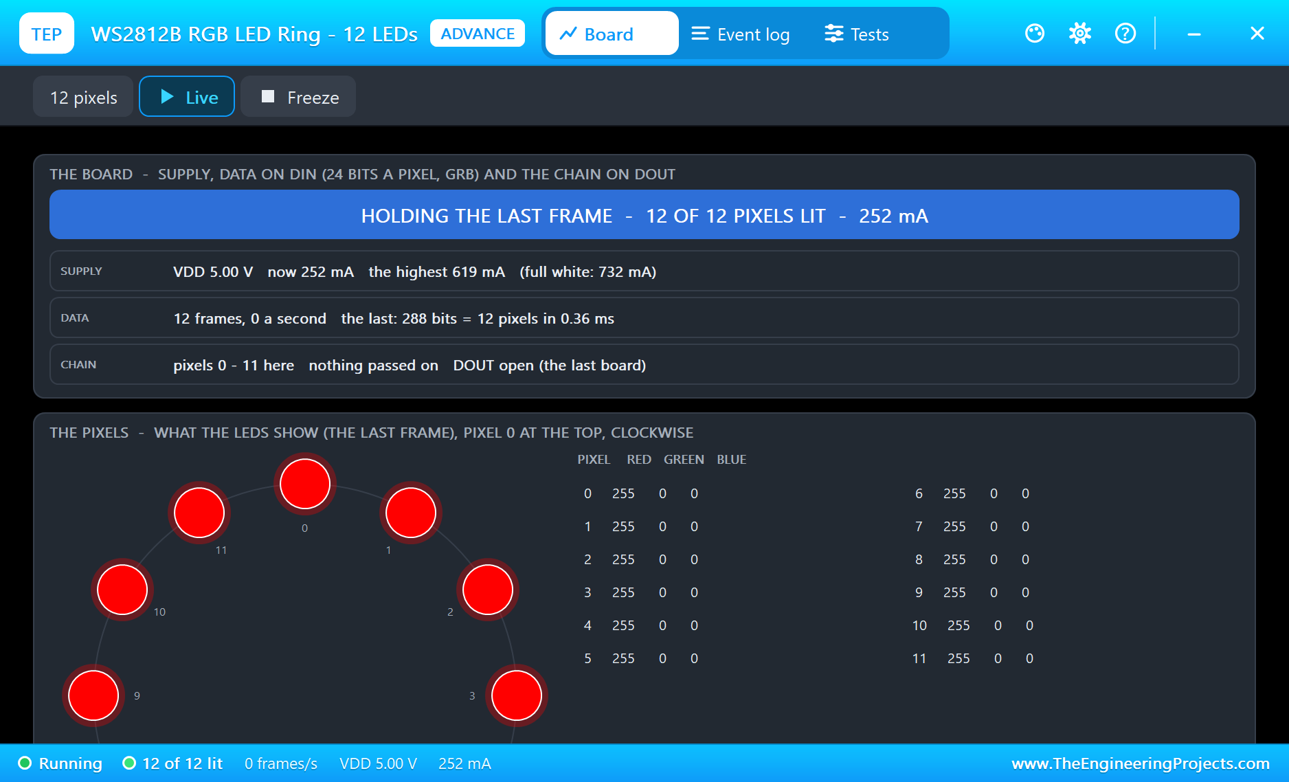
For the demo we built a smart night lamp. An LDR light sensor watches the room, and a 12-LED WS2812B ring grows brighter as the room gets darker. A phone changes the colour and the mode, the board's own RGB LED shows what the lamp is doing, and a laptop reads it all from the board's web page.
NOTICE: Proteus has no ESP32 model, so our team has put a lot of effort into building this board ourselves: the FireBeetle's pins, LEDs, buttons and Wi-Fi are all our own model, and your sketch compiles with our free TEP Boards for Proteus add-on. Your feedback is the fuel that keeps us going, so please tell us what you think in the comments below or in the DFRobot FireBeetle 2 ESP32-E board of our forum. And if our free libraries help you, you can buy us a coffee. So, let's get started with the DFRobot FireBeetle 2 ESP32-E Library for Proteus:
What is the FireBeetle 2 ESP32-E?
FireBeetle is DFRobot's family of low-power boards. The FireBeetle 2 ESP32-E measures 25.4 x 60 mm and carries an ESP32-WROOM-32E module: two Xtensa LX6 cores at 240 MHz, 520 KB of RAM, 4 MB of flash, 2.4 GHz Wi-Fi and Bluetooth. Around it DFRobot has added a USB-C port with a CH340 serial chip, a PH2.0 connector and charger for a 3.7 V Li-ion cell, a WS2812 RGB LED, a user LED, a user button, a reset button, and a GDI socket that takes DFRobot's small displays on a flat cable. The pads along the edges can be soldered straight onto your own PCB.
| FireBeetle 2 ESP32-E | ESP32 DevKit V1 | ESP32-S3 DevKitC-1 | |
|---|---|---|---|
| Battery | PH2.0 connector and charger | no | no |
| Sleep current | very low, a cut pad saves more | high | high |
| LEDs | WS2812 and a user LED | a user LED | a WS2812 |
| Buttons | RST and a user button | EN and BOOT | RST and BOOT |
| Display socket | GDI | no | no |
| Best for | battery gadgets | the bench | heavy processing |
Why Use a Low-Power Board?
A normal development board wastes a lot of energy on its USB chip and its power regulator, and that waste continues even when the ESP32 sleeps. So a battery that should last months is flat in days. Boards like the FireBeetle are designed around that problem. A cuttable solder pad even removes a little more current, about 500 uA, at the price of the RGB LED working only on USB power. For anything that lives on a shelf, in a garden or inside a toy, those details matter more than clock speed.
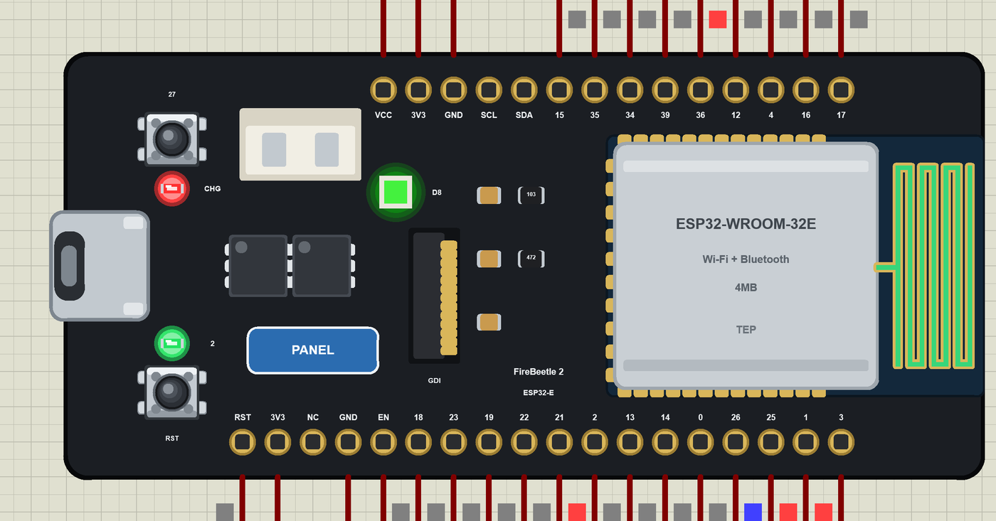
Features of the FireBeetle 2 ESP32-E Library for Proteus
- The board as it looks: the black FireBeetle with USB-C, RST and the user button, the charging and user LEDs, the PH2.0 connector, the WS2812, the GDI socket, the ESP32-WROOM-32E module and the PCB antenna.
- Your sketch: a .hex for "FireBeetle 2 ESP32-E (TEP Proteus)" with the board's D and A names - analogRead 0 to 4095, analogWrite and ledc PWM, attachInterrupt, Serial, Serial2, Wire and SPI.
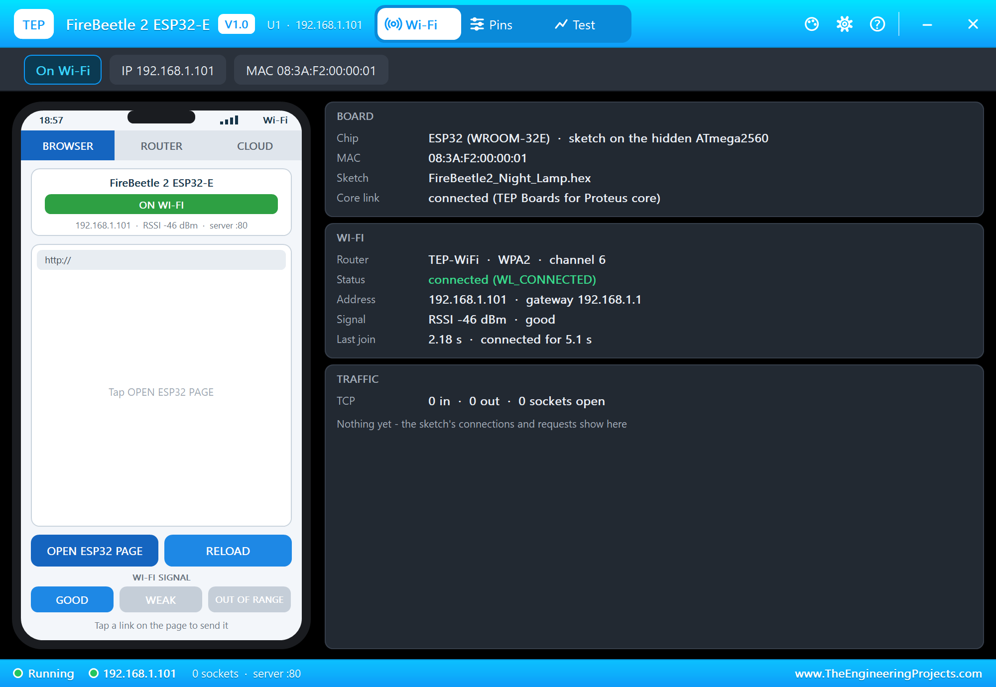
- Wi-Fi: WiFi.begin, WebServer, HTTPClient, mDNS and NTP on our virtual network; the board is 192.168.1.101 in the demo.
- LEDs and buttons work: rgbLedWrite colours the WS2812 on the part, GPIO2 drives the user LED, the user button pulls GPIO27 LOW and RST resets the board.
- The panel and the serial monitor: the board's panel (Wi-Fi, Pins, Test) and the built-in serial monitor with Monitor, Plotter and Board tabs - our TEP header, no Windows title bar.
- A complete package: about 4.1 MB with the board, the add-on, the LDR, WS2812B and monitor libraries and the demo, without the source code of the models.
The FireBeetle 2 ESP32-E in Proteus
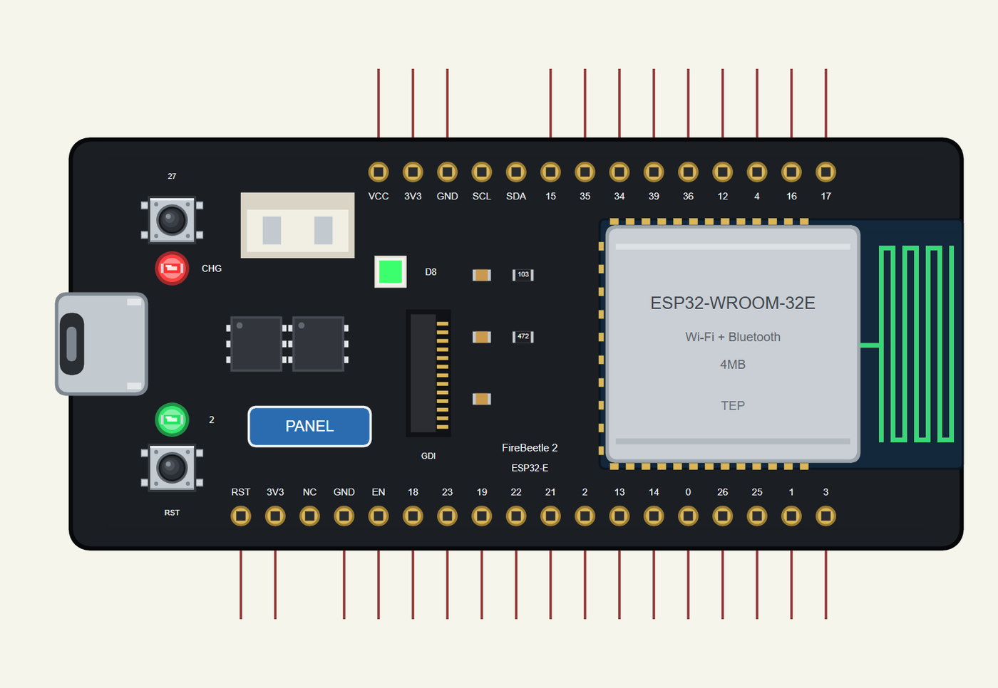
Search FIREBEETLE in Pick Devices; the device FIREBEETLE 2 ESP32-E is in TEPFIREBEETLE2.LIB (Microprocessor ICs, ESP32 Boards), with the prefix U. The board lies with the USB-C port on the left. Click that port to open the serial monitor, and the PANEL pad (or the module) to open the board's panel. One FireBeetle can be placed in a design.
The Pins
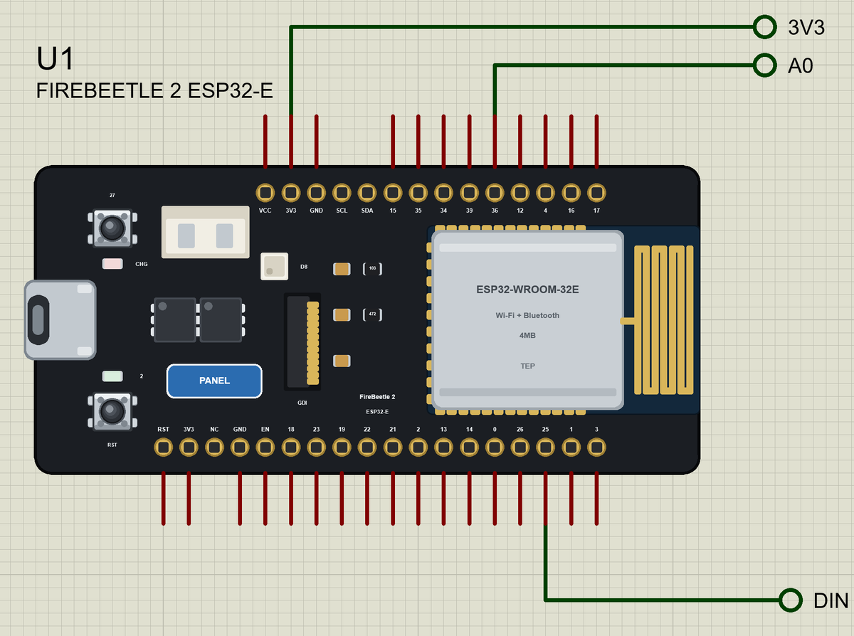
| Pins | GPIO | What the library does with them |
|---|---|---|
| SDA / SCL | 21 / 22 | Wire |
| SCK, MISO, MOSI | 18, 19, 23 | SPI |
| TX / RX | 1 / 3 | Serial, the board's monitor |
| D10 / D11 | 17 / 16 | Serial2 |
| A0 to A3 | 36, 39, 34, 35 | analog inputs only |
| A4 | 15 | analogRead, GPIO, PWM, interrupt |
| D2, D3, D5, D6, D7, D12, D13 | 25, 26, 0, 14, 13, 4, 12 | GPIO, PWM, interrupt |
| D9 | 2 | GPIO and the user LED |
| On the board | 5 and 27 | the WS2812 and the user button |
The silk on the real board gives the GPIO numbers, and the pinout chart gives the D and A names, so the part shows the numbers and the sketch can use either.
Download DFRobot FireBeetle 2 ESP32-E Library for Proteus
Click the button below to download DFRobot-FireBeetle-2-ESP32-E-Library-for-Proteus-v1.0.zip (about 4.1 MB, without the source code of the models):
DFRobot FireBeetle 2 ESP32-E Library for Proteus V1.0- README.txt: installation, the demo, the pins, the properties, troubleshooting and the limits.
- Proteus Library Files:
TEPFIREBEETLE2.LIBand the demo's parts:TEPLDR.LIB,TEPWS2812.LIB,TEPLAPTOP.LIBandTEPMOBILE.LIB. - Proteus Model Files:
TEPNET.DLL(the board, the laptop, the phone and the network),TEPLDR.DLLandTEPWS2812.DLL. - Arduino Code: the demo sketch and the TEP Boards for Proteus add-on 1.45.0.
- Proteus Simulation: the demo project, its HEX file and copies of the DLLs.
No Proteus yet? Read How to Download and Install Proteus 7 and 8. New to libraries? Follow How to Install a New Library in Proteus.
How to Install DFRobot FireBeetle 2 ESP32-E Library for Proteus
- Close Proteus and extract the whole zip file, for example to your Desktop.
- Copy the files from Proteus Library Files into the LIBRARY folder of Proteus.
- Copy the DLLs from Proteus Model Files into the MODELS folder, replacing an older TEPNET.DLL.
- Delete
TEPFIREBEETLE2.IDXfrom the LIBRARY folder if it is there. - For your own sketches, copy Arduino Code\TEP Boards for Proteus\hardware into your Arduino sketchbook (Documents\Arduino) and restart the Arduino IDE; the board is FireBeetle 2 ESP32-E (TEP Proteus). Install Adafruit NeoPixel from the Library Manager.
- Start Proteus, press P and search for FIREBEETLE.
Demo: a Smart Night Lamp
A night lamp is a perfect battery project. It should do nothing during the day, wake up gently as the light fades, and need no attention at all. Ours goes a step further: since it has Wi-Fi, you can change its colour from a phone, force it on, or switch it off from bed.
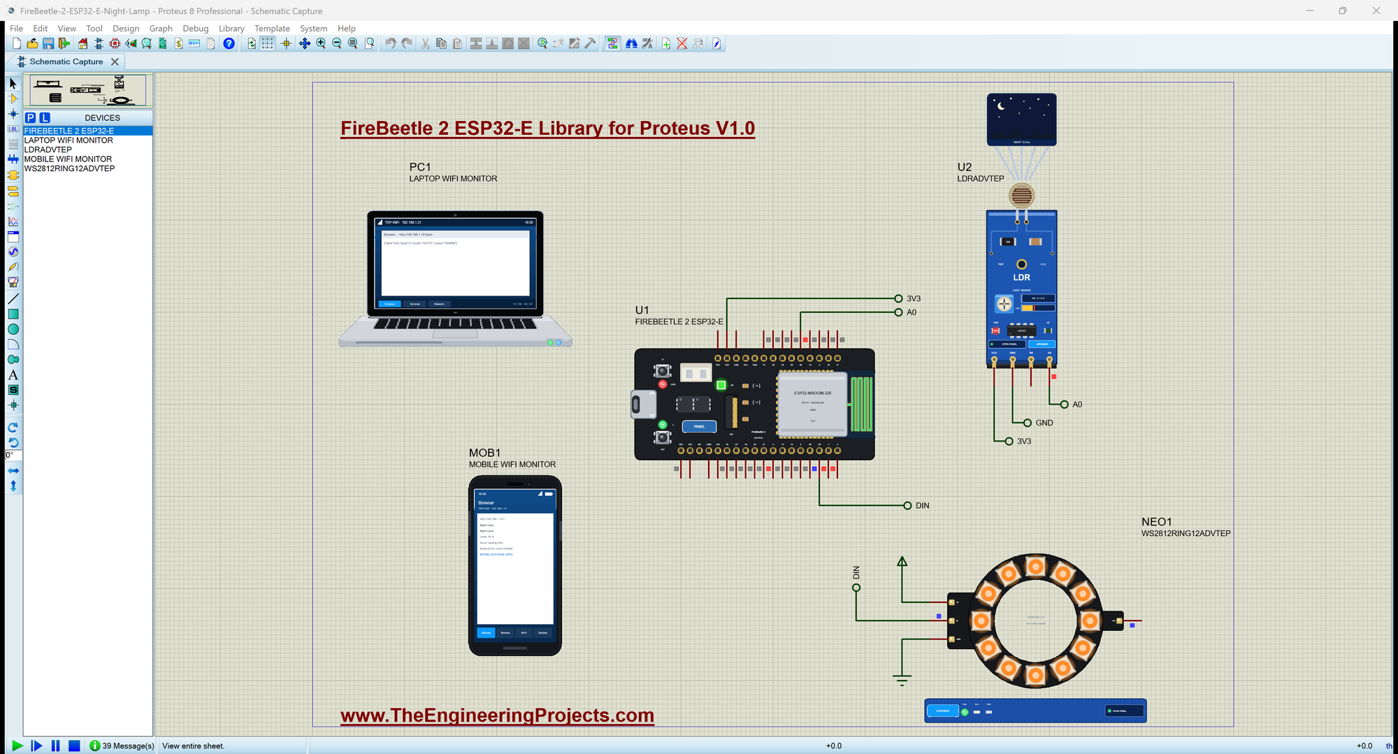
Open FireBeetle-2-ESP32-E-Night-Lamp.pdsprj. U1 runs FireBeetle2_Night_Lamp.hex. U2 is the module from our LDR Sensor Library for Proteus and NEO1 the ring from our WS2812B NeoPixel Library for Proteus - both in the Advance version, so they open their pop-up windows at Run. PC1 is the Laptop WiFi Monitor and MOB1 the Mobile WiFi Monitor.
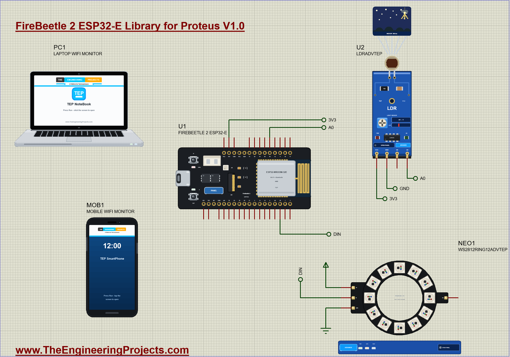
| Module pin | Net label | Board pin | What it does |
|---|---|---|---|
| LDR A0 | A0 | A0 (GPIO36) | the light reading |
| LDR VCC, GND | 3V3, GND | 3V3, GND | the supply, so that A0 stays under 3.3 V |
| Ring DIN | DIN | D2 (GPIO25) | the LED data |
| Ring 5V, GND | VCC, GND | VCC, GND | the supply |
How an LDR Measures Light
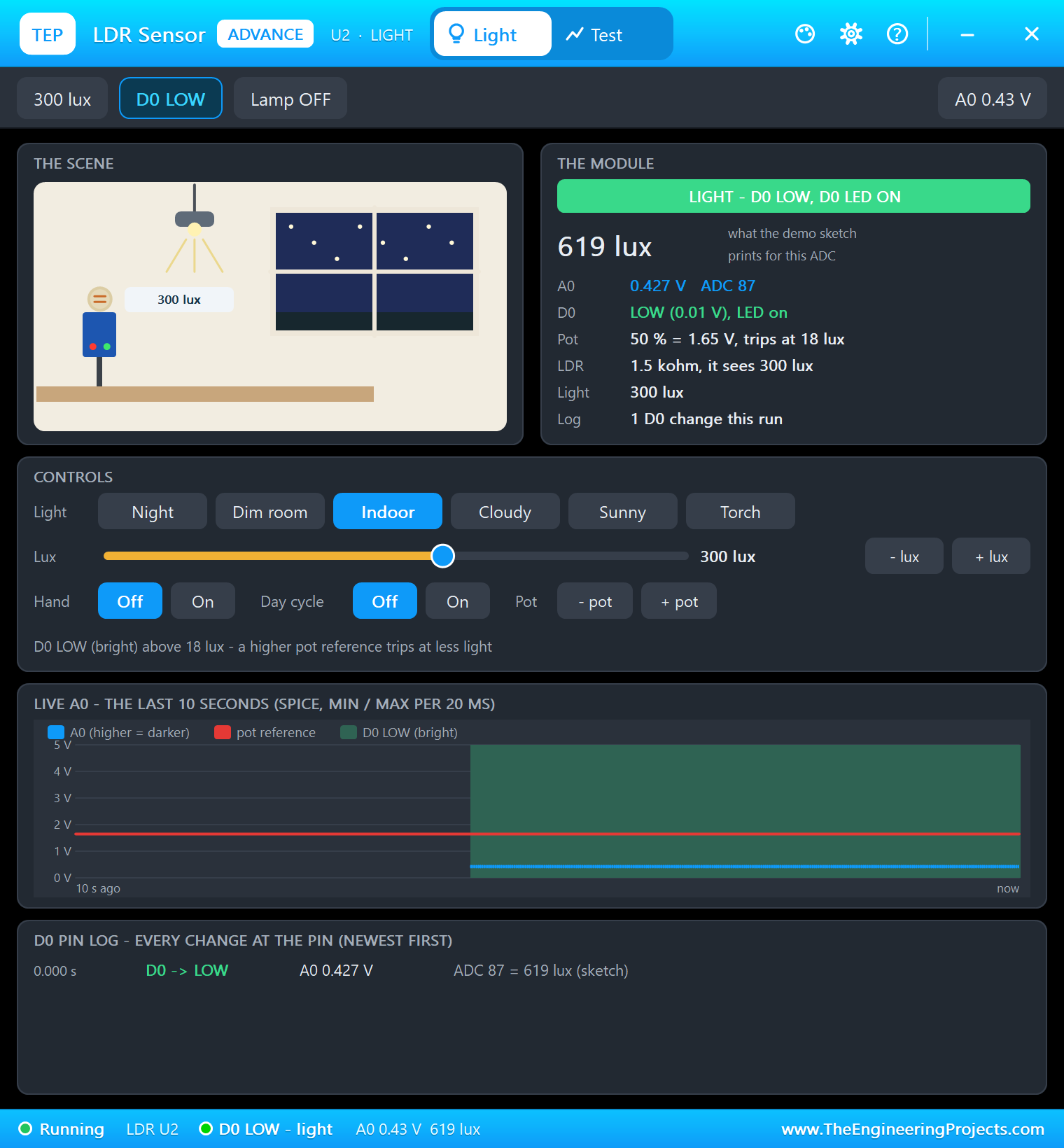
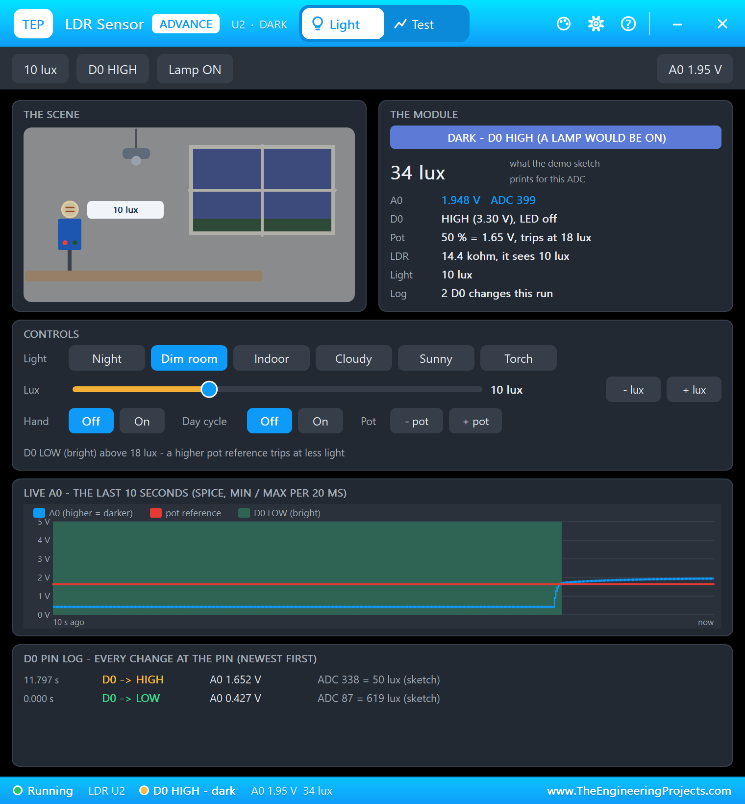
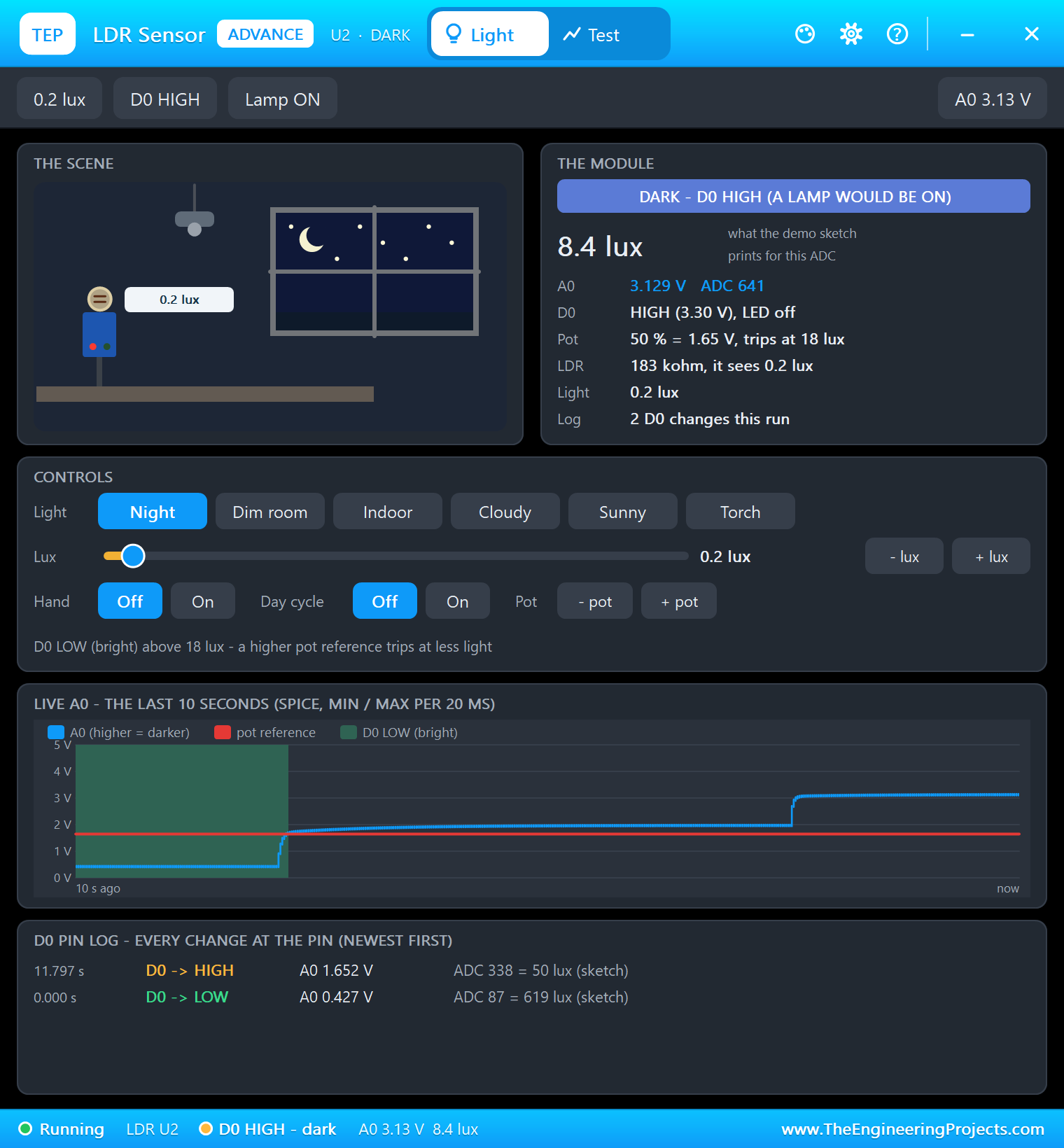
An LDR, or light dependent resistor, is a small slice of cadmium sulphide whose resistance falls as more light hits it. In the dark it can reach a megohm; in a bright room it drops to a kilohm or two. An ADC cannot read a resistance, so the module puts the LDR in a voltage divider with a fixed 10 k resistor. The more resistance the LDR has, the more of the supply appears on A0, so on this module a higher reading means a darker room. Our sensor reads 0.43 V at 300 lux, and that is the 529 you will see in the log. The response is far from a straight line, which is normal: each step down in light adds a big jump in resistance.
There is one trap on an ESP32. Its ADC stops at 3.3 V, so the module must run from the 3V3 pin, not from 5 V. The sketch only needs one line to read it, and it keeps the user LED blinking so that you can see it working:
void readLight() {
  if (millis() < nextRead) return;
  nextRead = millis() + 500;
  dark = analogRead(LDR_PIN);
  blinkOn = !blinkOn;
  digitalWrite(LED_BUILTIN, blinkOn);
}
From Darkness to Brightness
The lamp stays off below a reading of 800, which is a normal lit room, and reaches full brightness at 3600, which is close to dark. Between them the sketch scales the reading to a percentage, using long because the product is too big for a 16-bit int in the simulation. constrain() keeps the result between 0 and 100:
int lampPercent() {
  if (mode == OFF) return 0;
  if (mode == ON) return 100;
  long p = (long)(dark - DARK_START) * 100 / (DARK_FULL - DARK_START);
  return constrain(p, 0, 100);
}
How WS2812B LEDs Work
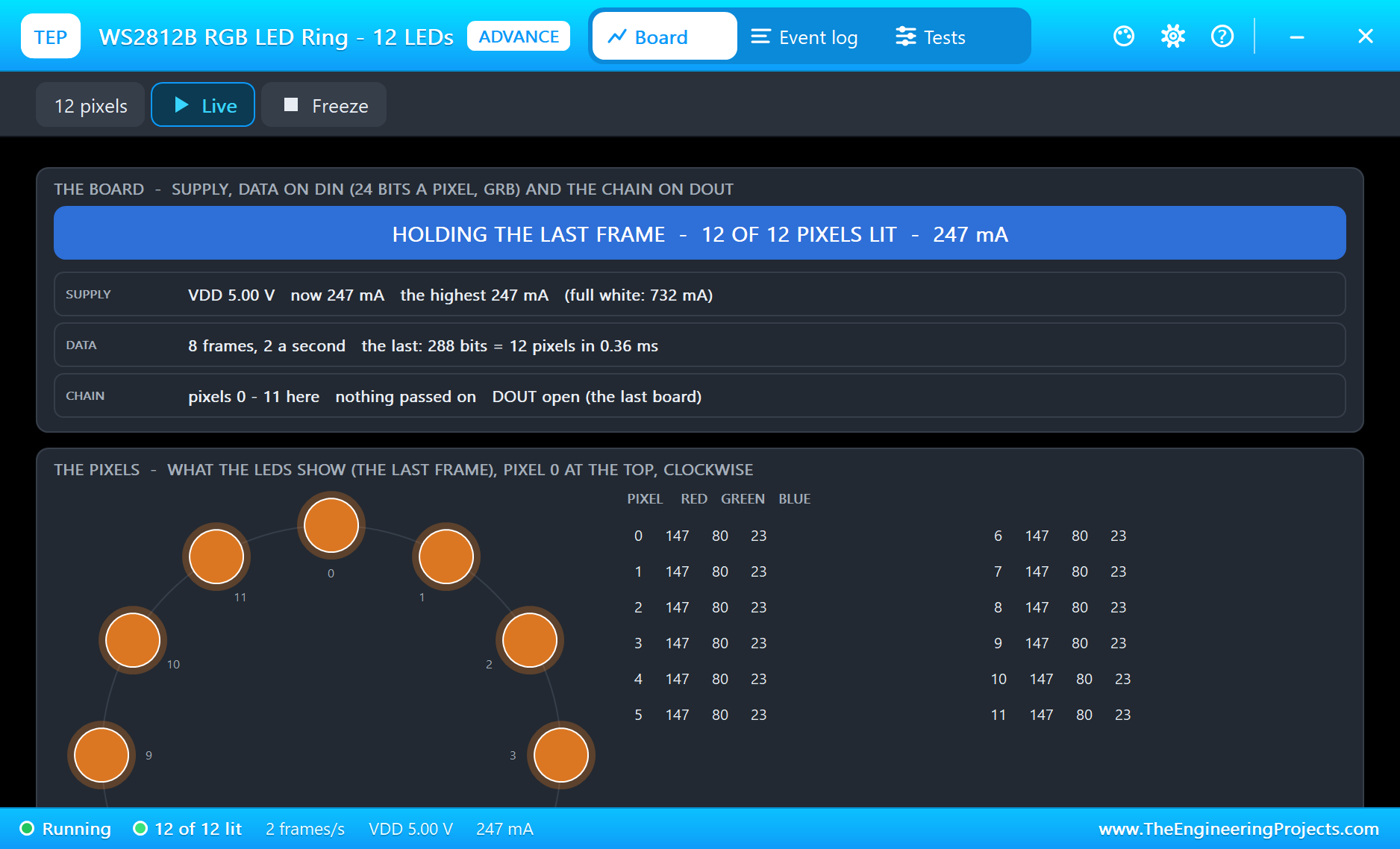
A WS2812B is an RGB LED with a tiny controller inside. It takes one data wire, and the bits are coded in the width of each pulse: about 0.4 us high for a 0 and 0.8 us high for a 1, at 800 kHz. The first LED keeps the first 24 bits, which are its green, red and blue values, and passes everything else on to the next. So twelve LEDs need one pin and 12 x 24 bits, and a low pause of more than 50 us tells them all to show the new colours. The Adafruit NeoPixel library does this timing for us. The sketch sends a new frame only when something changes, which keeps the loop free for the web server:
void showLamp() {
  percent = lampPercent();
  if (percent == shownPercent && !redraw) return;
  byte level = percent * 255L / 100;
  ring.setBrightness(level);
  ring.fill(ring.Color(COLOUR_RGB[colour][0], COLOUR_RGB[colour][1], COLOUR_RGB[colour][2]));
  ring.show();
  if (mode == AUTO) rgbLedWrite(RGB_BUILTIN, 0, 60, 0);
  else if (mode == ON) rgbLedWrite(RGB_BUILTIN, 60, 60, 60);
  else rgbLedWrite(RGB_BUILTIN, 0, 0, 0);
  if (shownPercent >= 0) { Serial.print(F("Lamp ")); Serial.print(percent); Serial.println(F(" %")); }
  shownPercent = percent;
  redraw = false;
}
The Modes and the Button
The modes are a small enum, and the button moves to the next one. The sketch watches for the moment the pin goes from HIGH to LOW, so one press is one step however long you hold it. The web page and the monitor call the same function, so all three stay in step:
void changeMode(const char *from) {
  mode = (Mode)((mode + 1) % 3);
  redraw = true;
  Serial.print(F("Mode ")); Serial.print(MODE_NAME[mode]); Serial.print(F(" (")); Serial.print(from); Serial.println(F(")"));
}
void readButton() {
bool now = digitalRead(BUTTON_PIN);
if (buttonWas == HIGH && now == LOW) changeMode("the user button");
buttonWas = now;
}The JSON Page
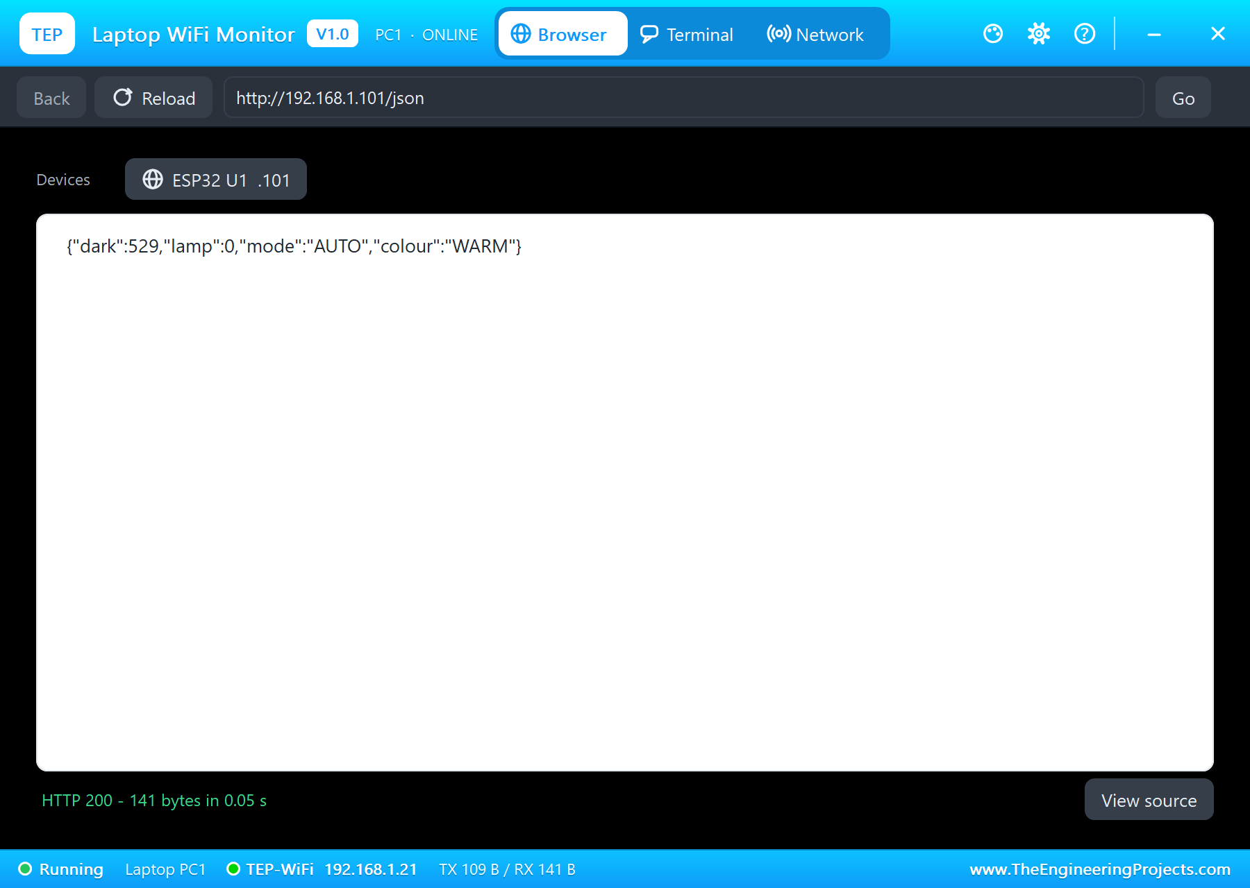
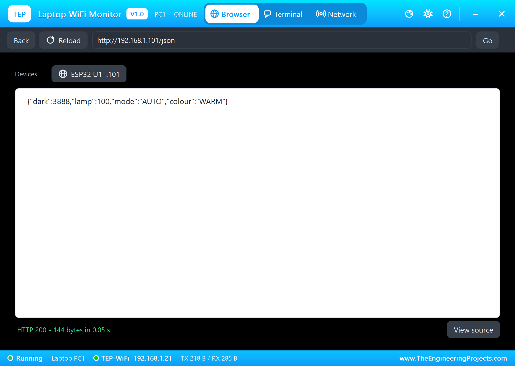
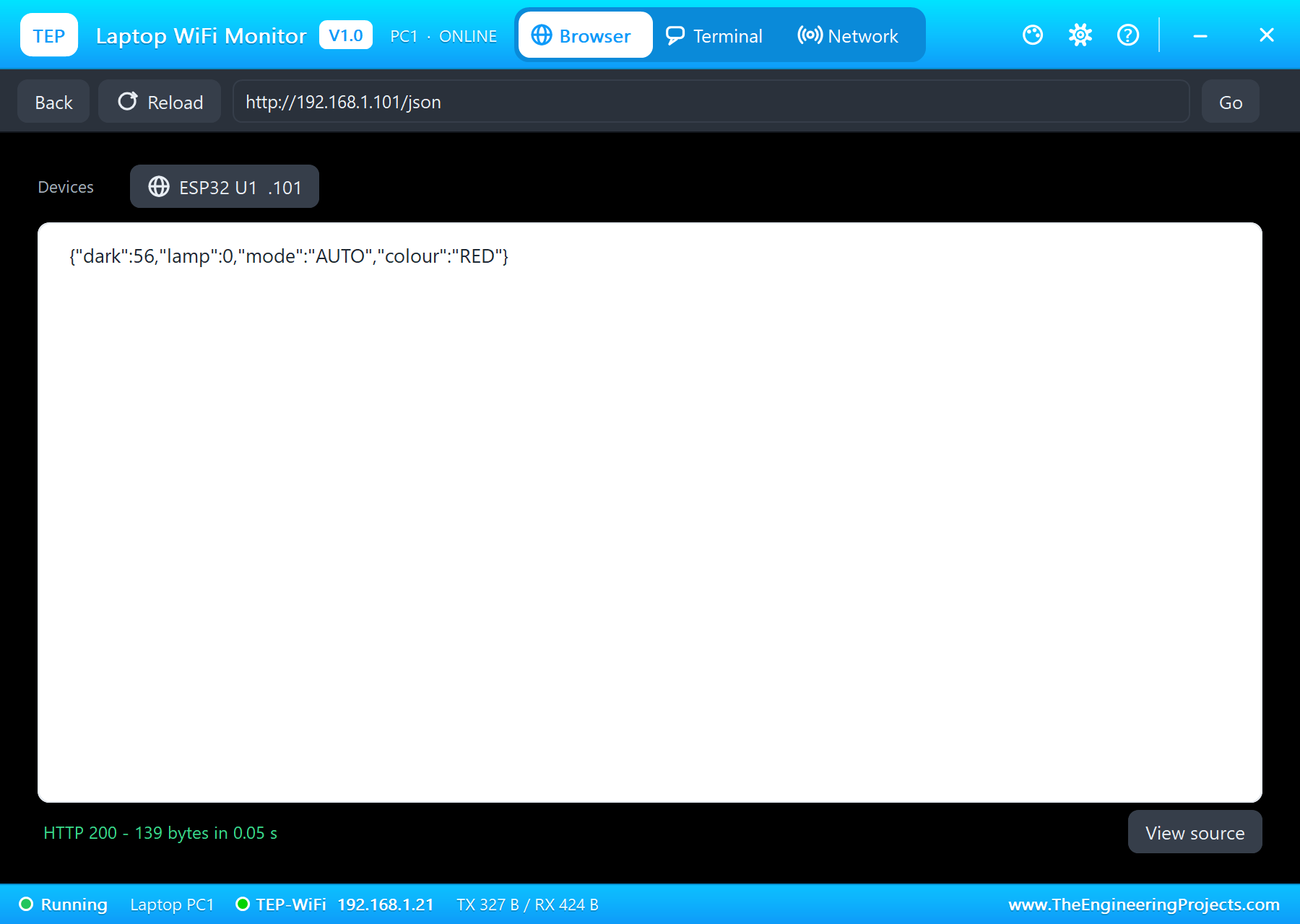
/ is the page for a person, with three buttons. /json is one line for a program, which is what the laptop opens. A home automation system could read this line every minute and learn when the room goes dark:
void handleJson() {
  String j = "{\"dark\":" + String(dark) + ",\"lamp\":" + String(percent) + ",\"mode\":\"" + MODE_NAME[mode] + "\",\"colour\":\"" + COLOUR_NAME[colour] + "\"}";
  server.send(200, "application/json", j);
}
Thinking About the Battery
A project like this is a good lesson in where the energy goes. One WS2812B LED at full white takes about 60 mA, so twelve of them can pull more than the ESP32 and its radio put together. The radio comes next, at well over 100 mA while it sends, and the chip itself is far behind. The way to stretch a 1000 mAh cell is to keep the lamp low, because a night light only needs a glow, and to turn the Wi-Fi off when nobody needs the page. A reading every half second is also more than a room needs. Once a minute would do, and the ESP32 could sleep in between. Those changes are easy to make on the real board, and the sketch here is already split into small functions so that you can try them.
Run the Demo
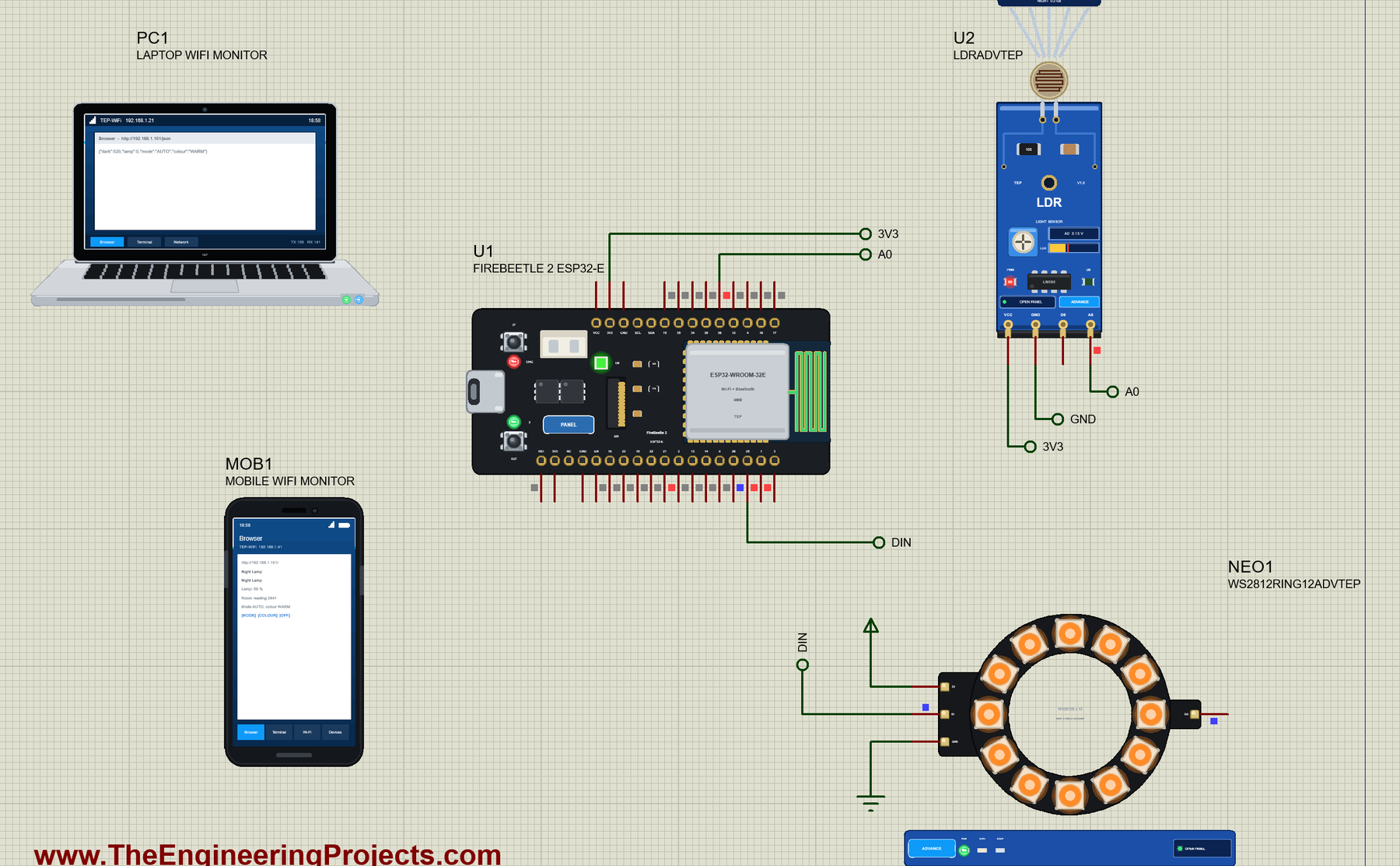
Press Run. The serial monitor opens and the board joins TEP-WiFi. The LDR starts at the Indoor setting, 300 lux, so the reading is low and the lamp stays off:
FireBeetle 2 Night Lamp - The Engineering Projects
Connecting to TEP-WiFi
Lamp page: http://192.168.1.101/
Dark 529  lamp 0 %  AUTO  WARM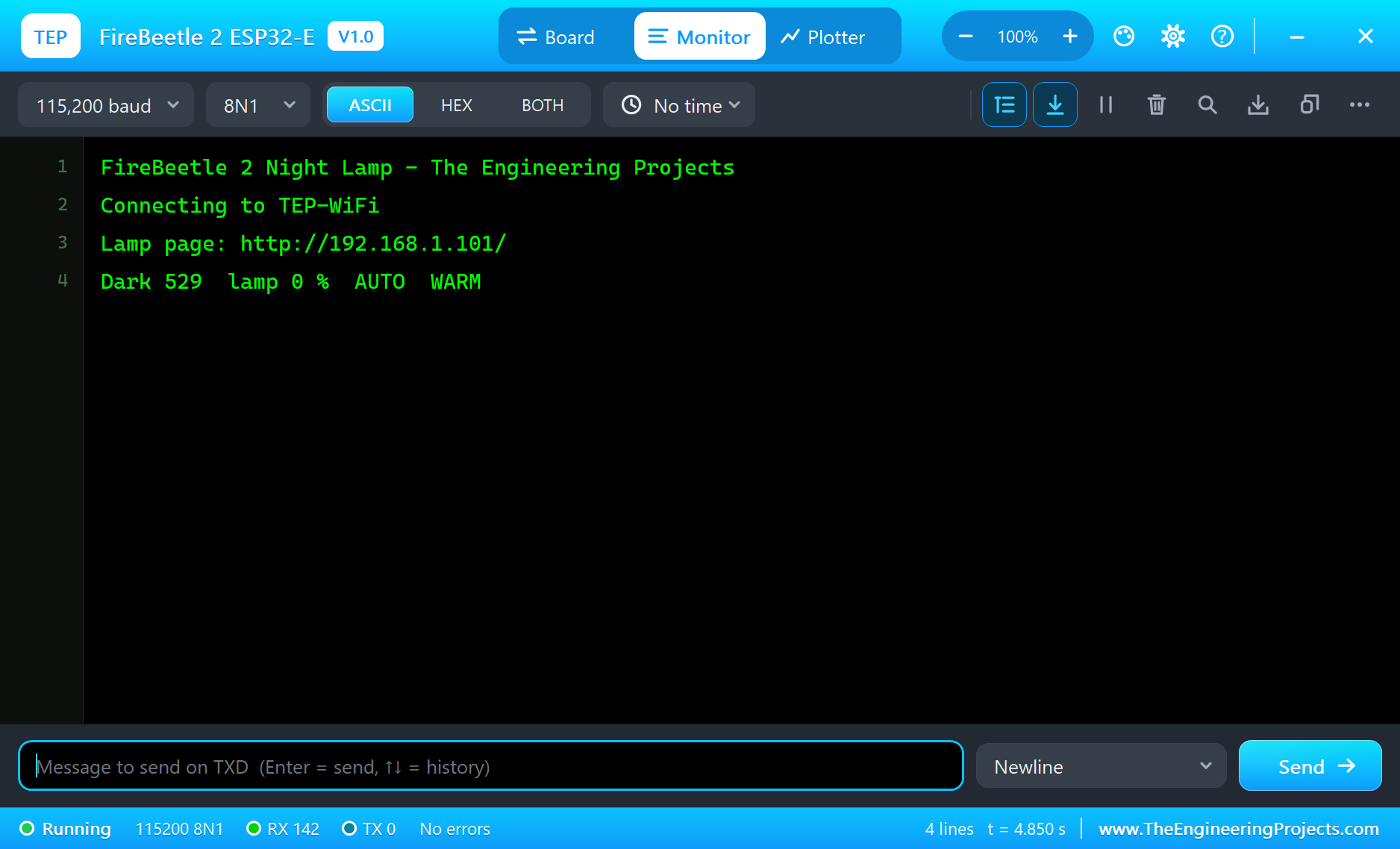
Open the Page
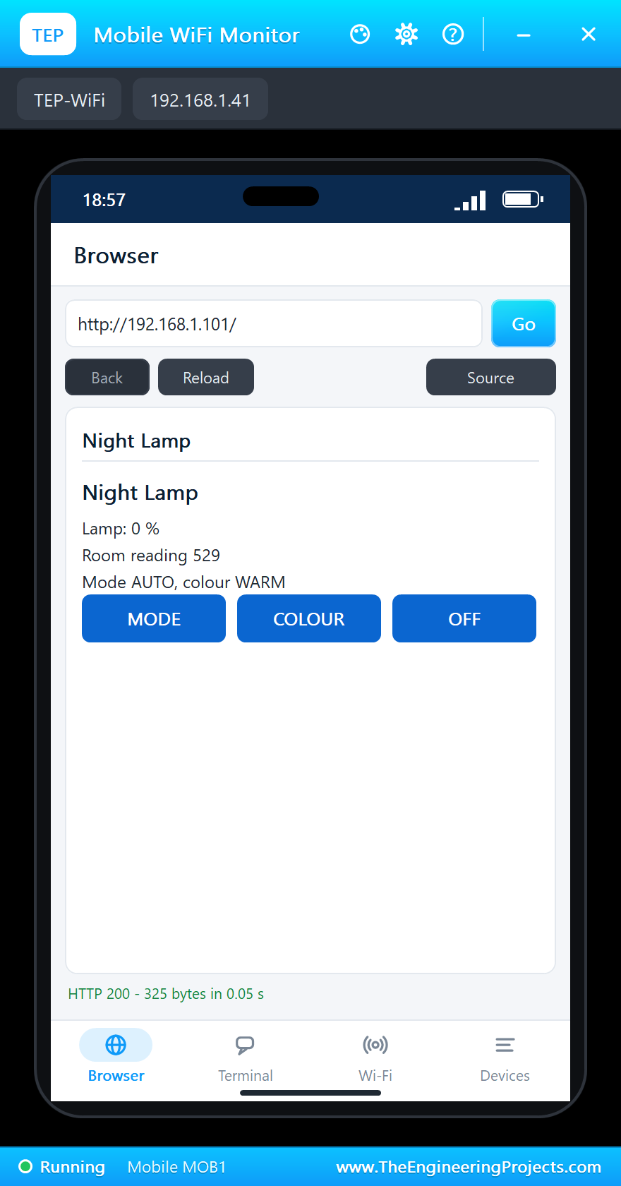
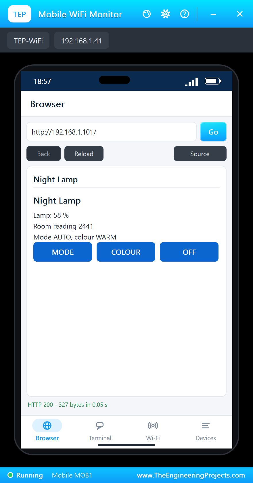
On the laptop click Browser and Go (the home page is http://192.168.1.101/json); on the phone the same with http://192.168.1.101/:
The Evening
Click Dim room on the LDR's window: 10 lux. The reading climbs and the lamp comes up to 58 %, a soft warm glow:
The Night
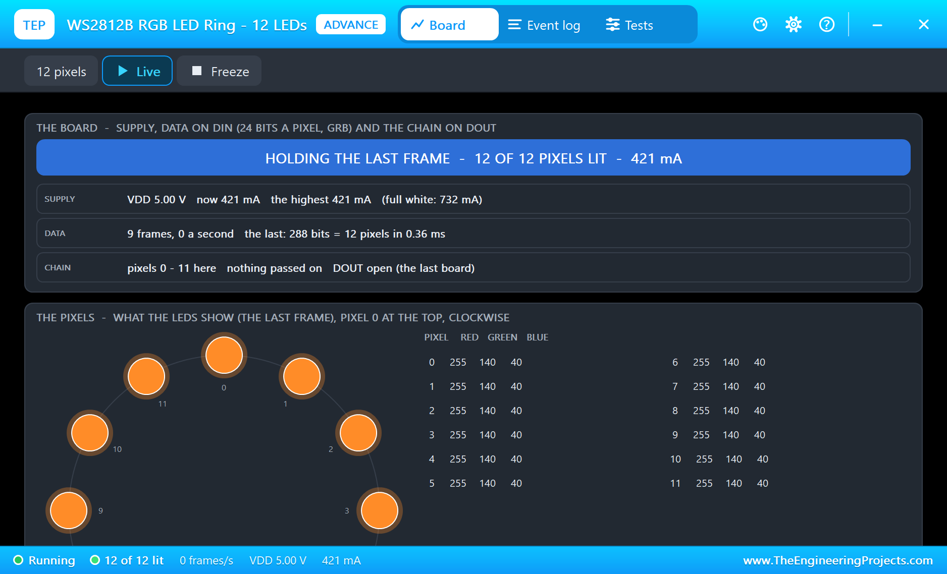
Click Night: 0.2 lux. The reading passes 3600 and the lamp is at 100 %:
Colours
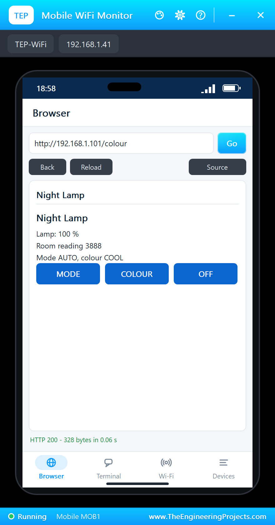
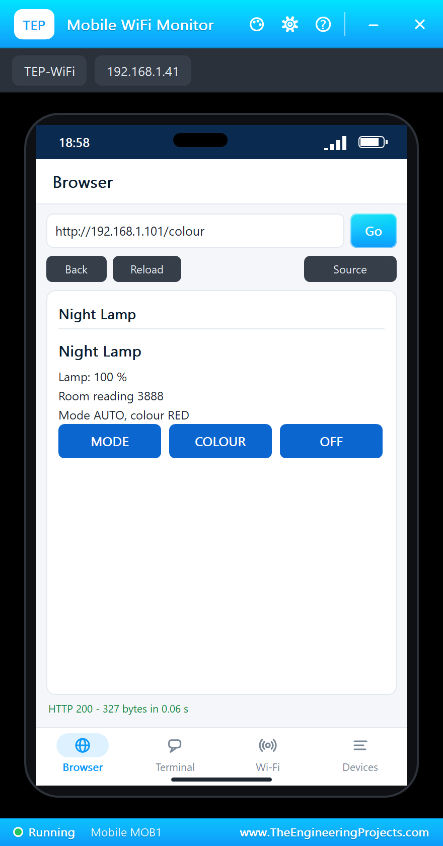
COLOUR on the phone moves from WARM to COOL to RED. Red is more than a party trick: it keeps your eyes used to the dark, which is why astronomers and pilots use it at night:
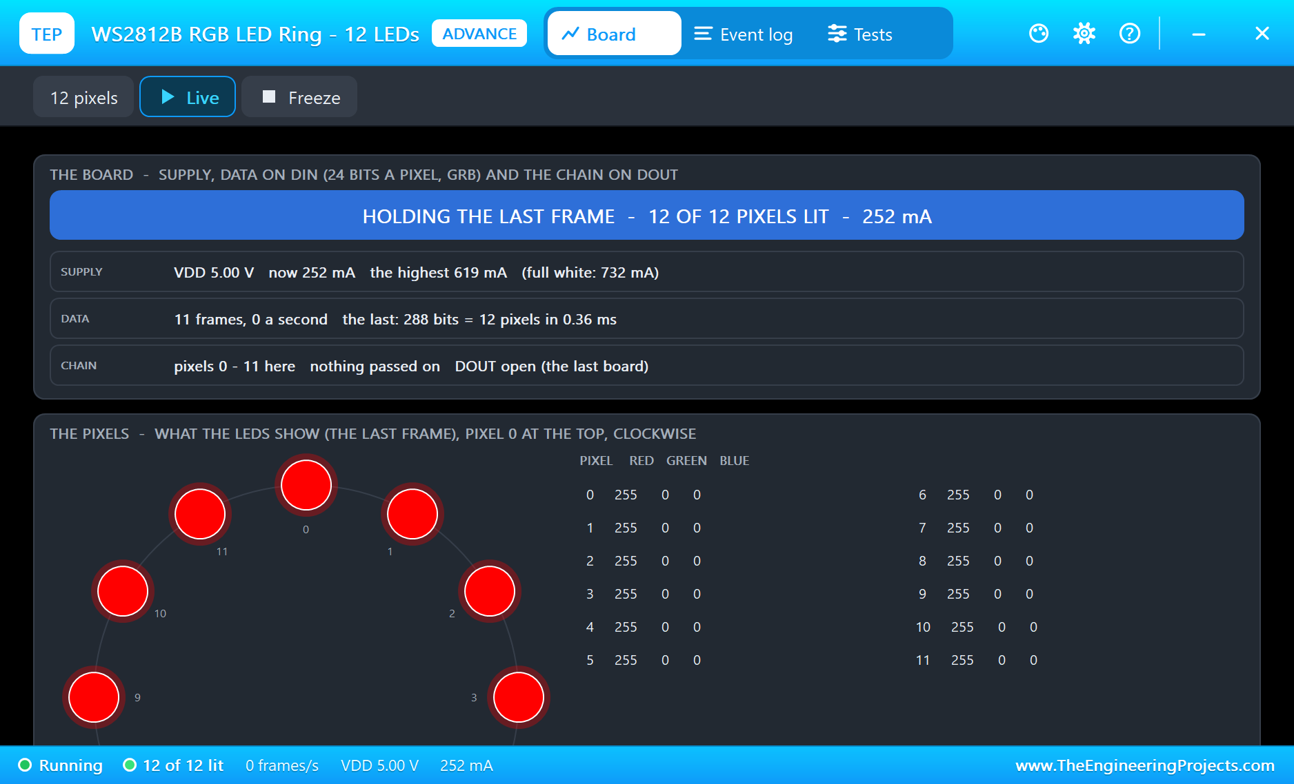
Modes
MODE moves from AUTO to ON. In ON the lamp ignores the sensor: click Sunny on the LDR's window and it stays at 100 %, with the board's RGB LED white. OFF puts the lamp out at once, and the RGB LED goes dark:
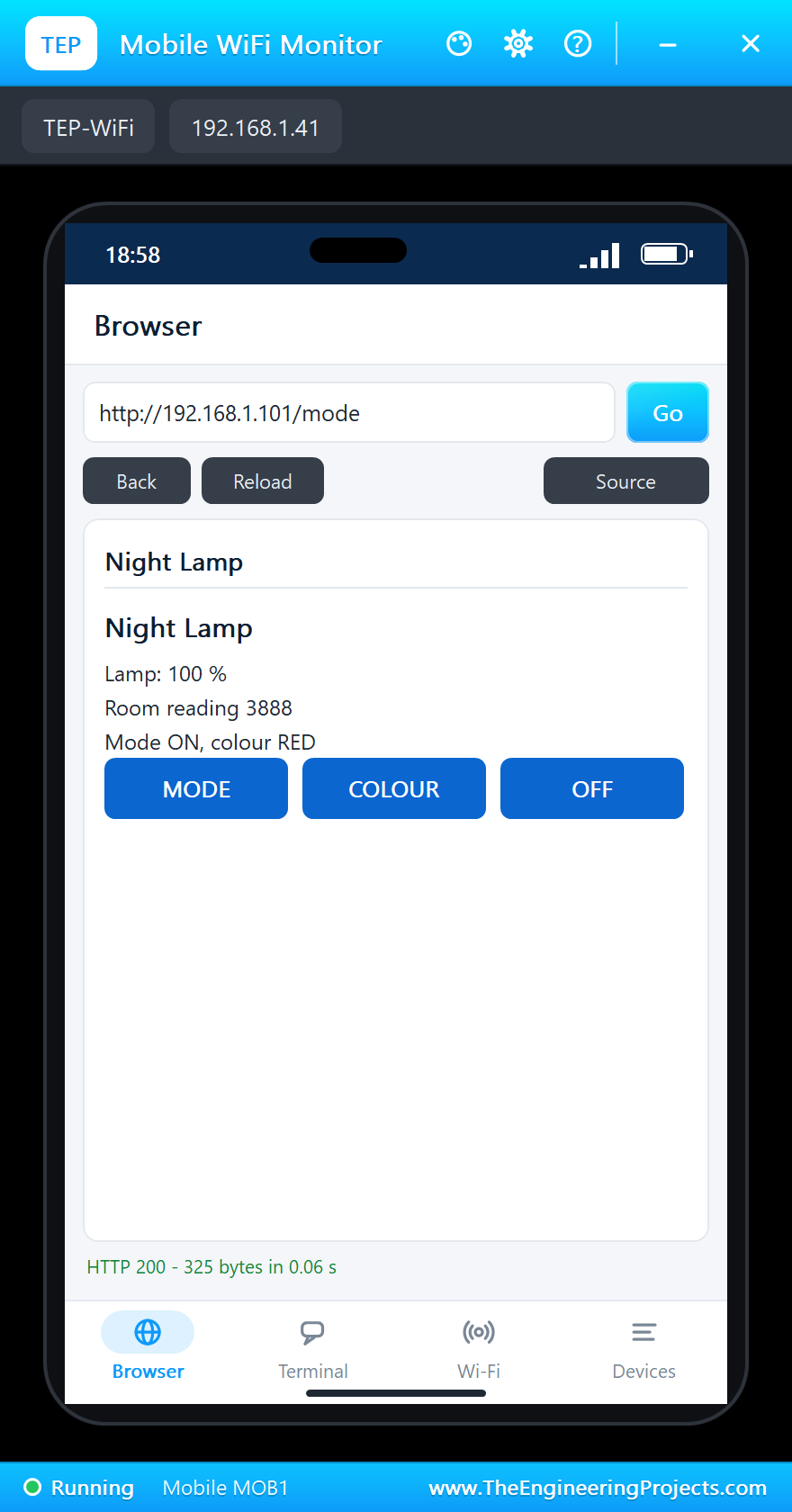
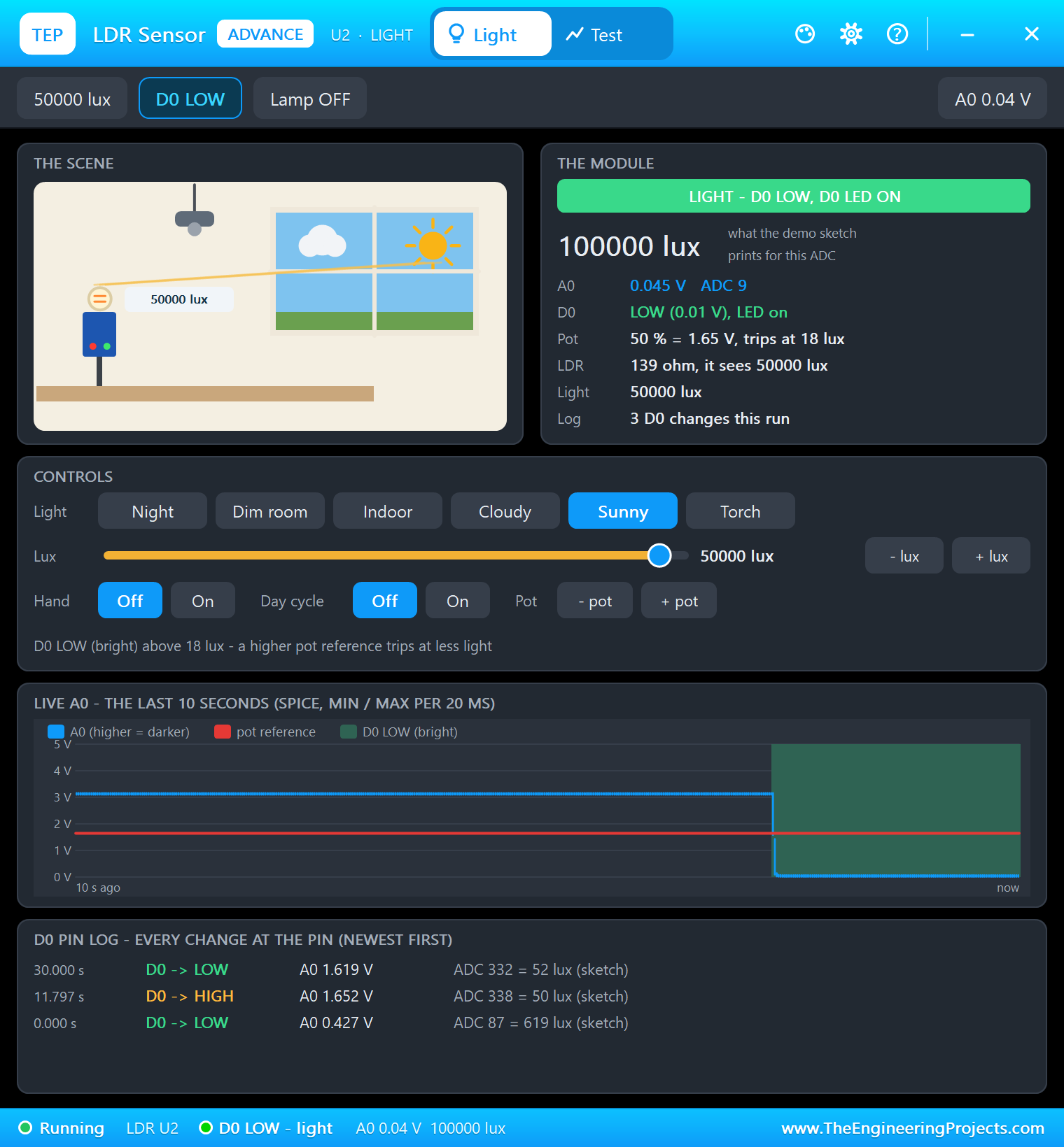
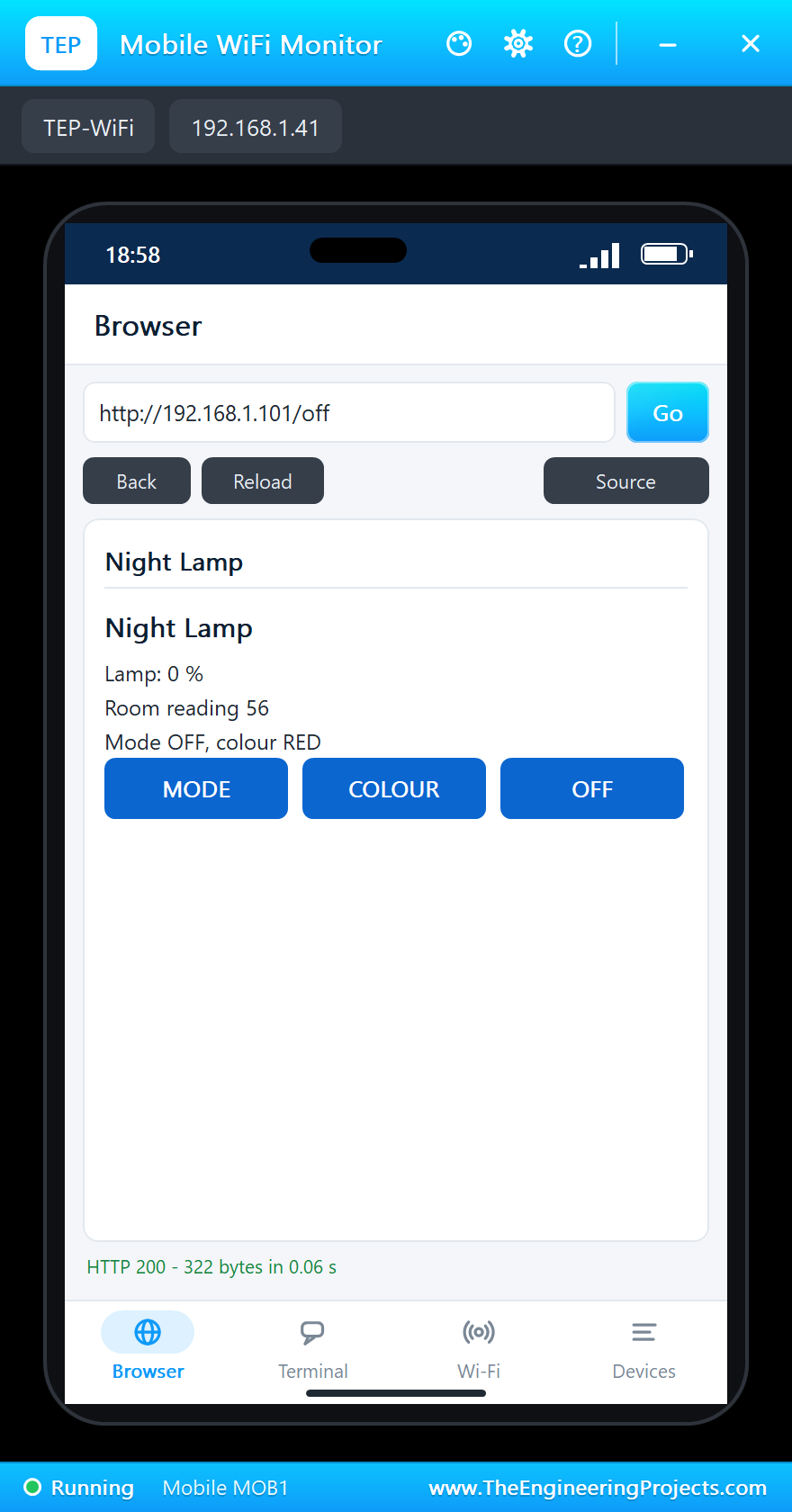
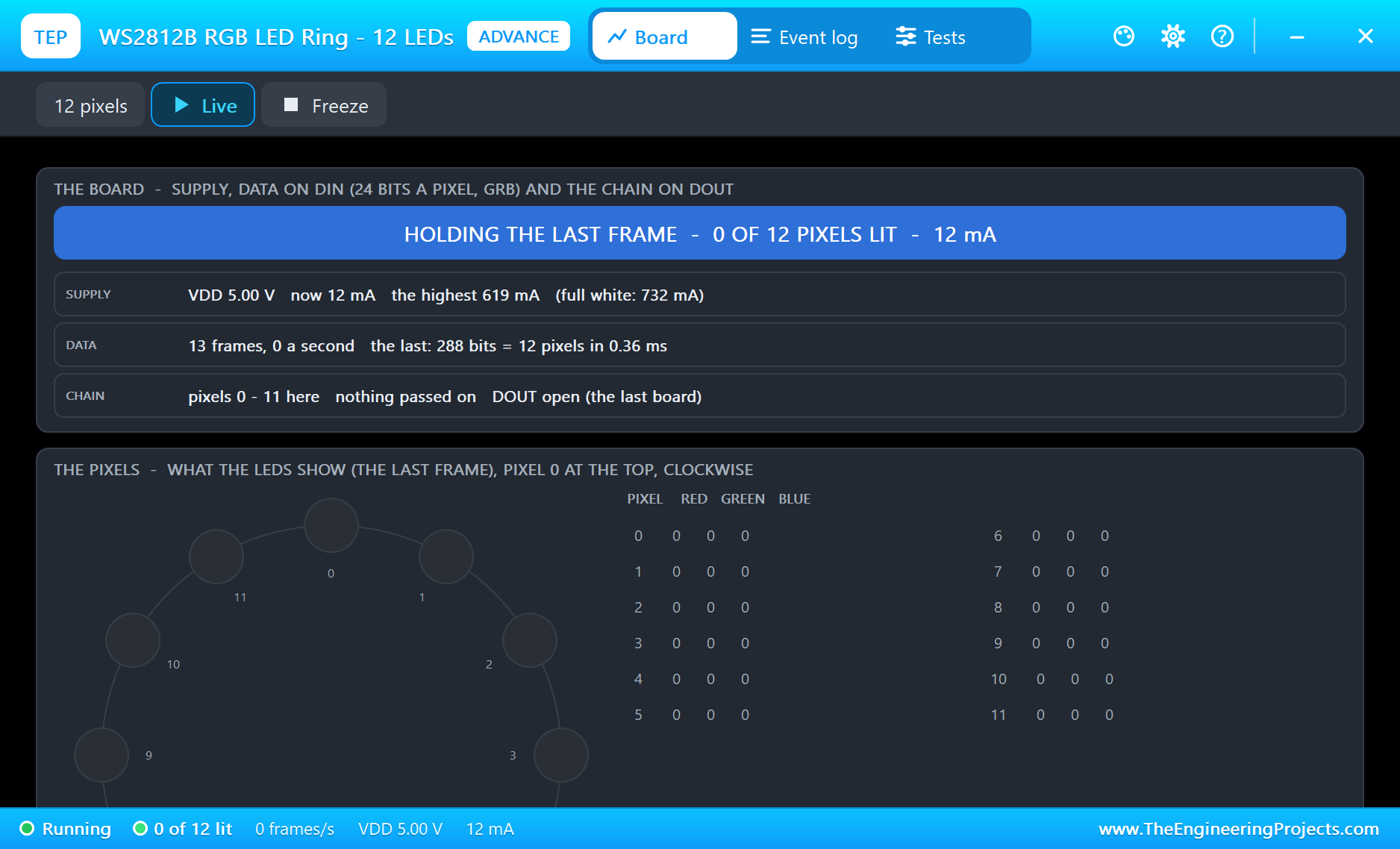
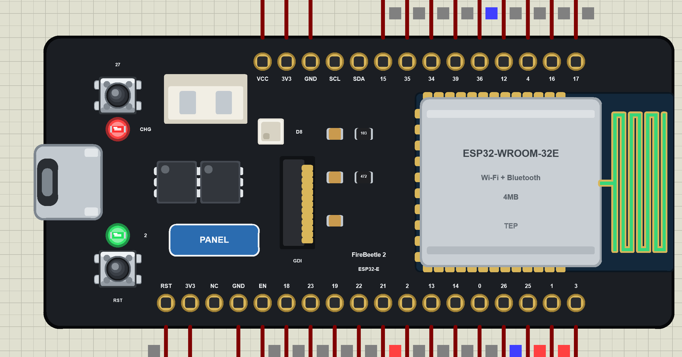
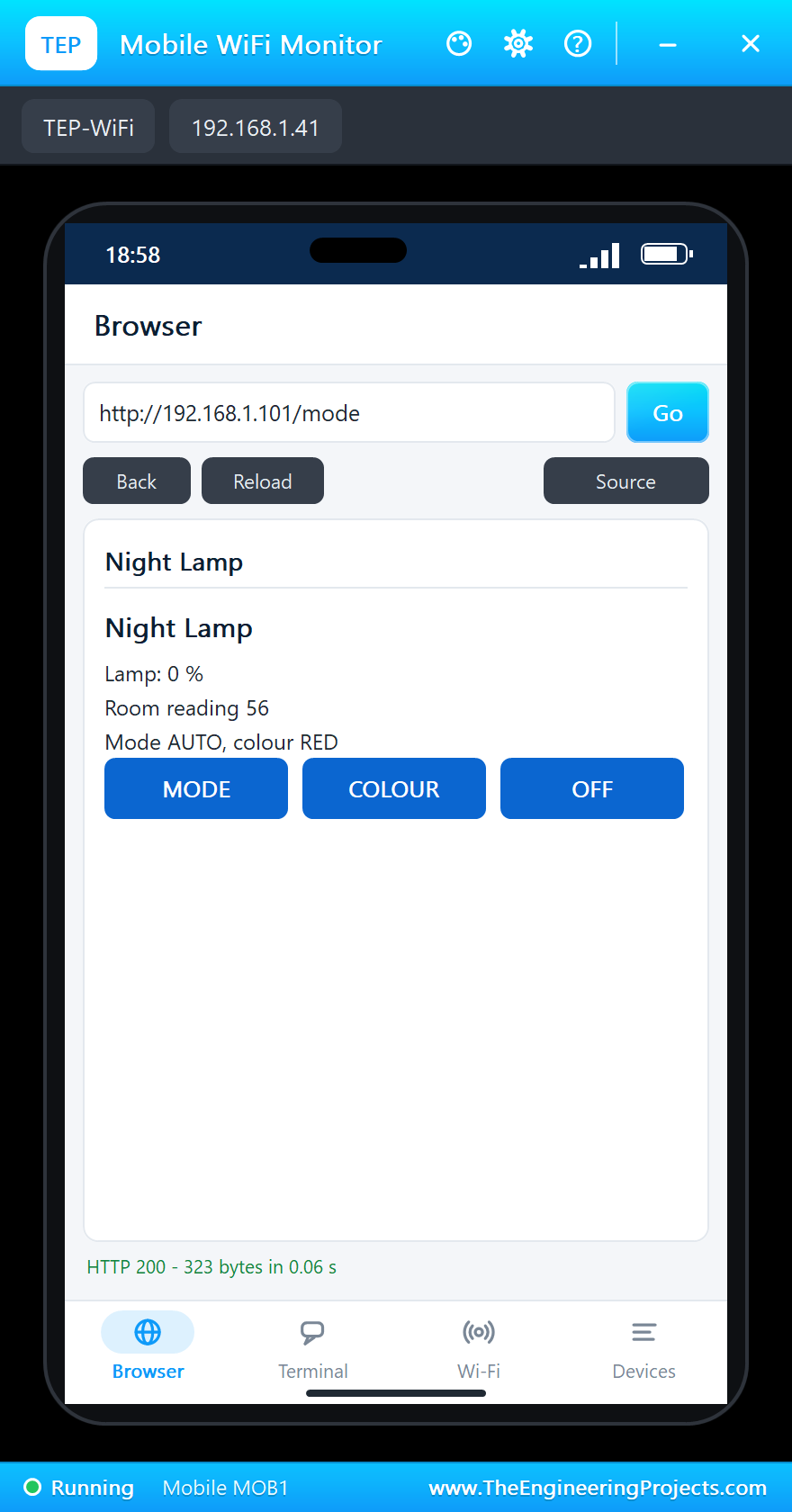
The built-in serial monitor, in the look of our TEP Serial Monitor Advance for Proteus, has followed everything:
Lamp 49 %
Dark 2190  lamp 49 %  AUTO  WARM
Lamp 53 %
Lamp 55 %
Lamp 56 %
Lamp 57 %
Lamp 58 %
Lamp 100 %
Dark 3888  lamp 100 %  AUTO  WARM
Colour COOL (the web page)
Lamp 100 %
Colour RED (the web page)
Lamp 100 %
Mode ON (the web page)
Lamp 100 %
Dark 56  lamp 100 %  ON  RED
Mode OFF (the web page)
Lamp 0 %
Mode AUTO (the web page)
Lamp 0 %
Dark 56  lamp 0 %  AUTO  RED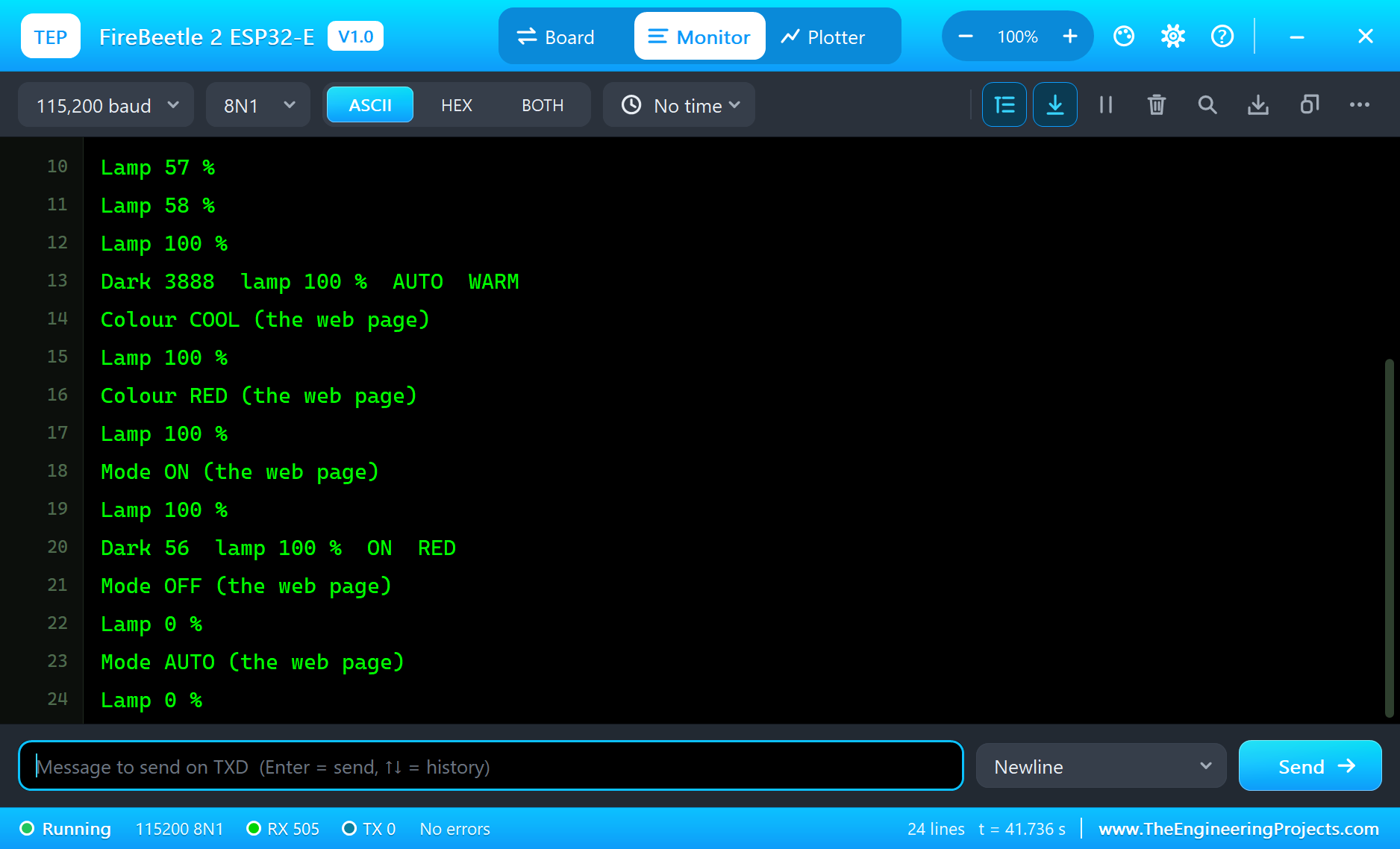
Try It Yourself
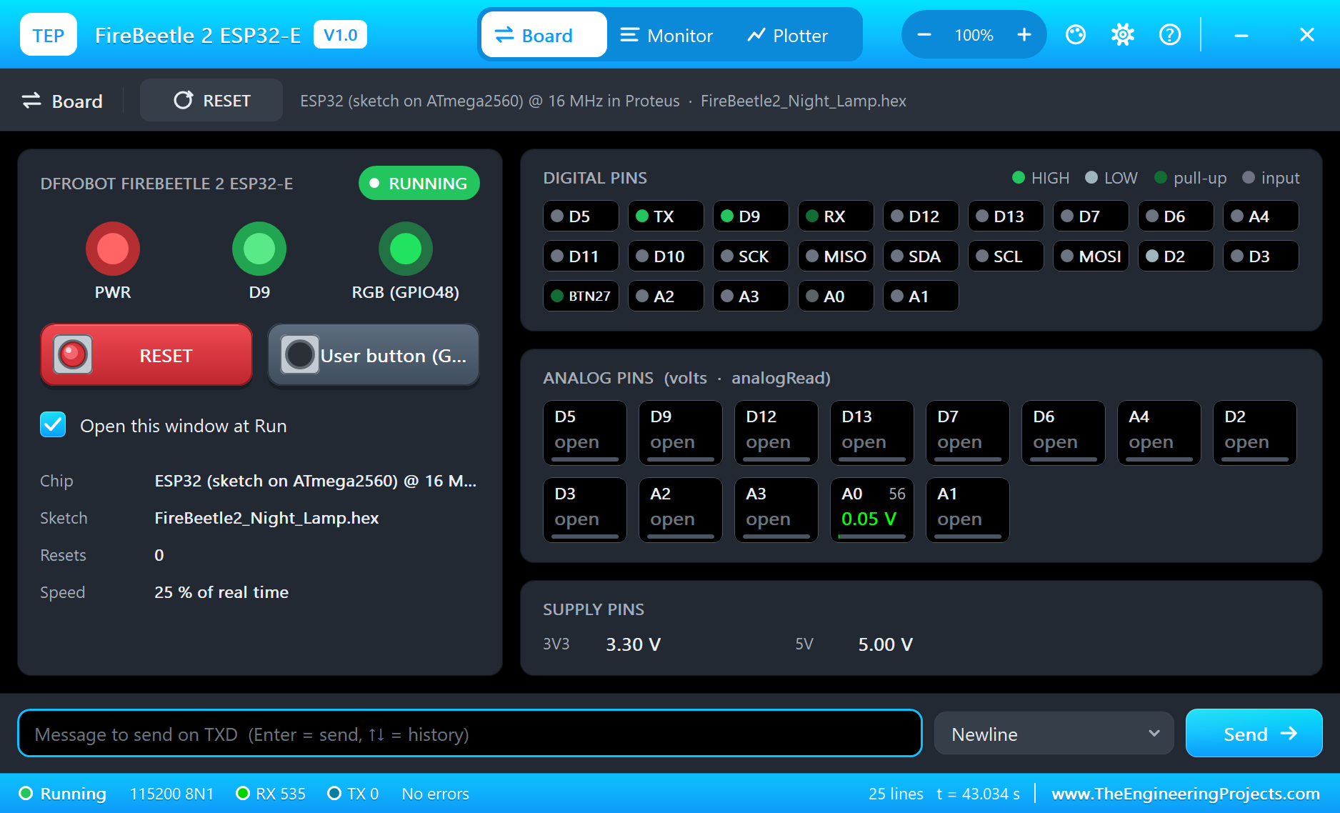
- Press the user button on the monitor's Board tab: the mode changes.
- Turn Day cycle on in the LDR's window and watch the lamp follow a whole day.
- Change
DARK_STARTandDARK_FULLand rebuild the sketch. - Type
STATUS,MODEorCOLOURin the monitor.
Ideas to Extend the Night Lamp
- Fade between levels instead of jumping, a few percent at each reading.
- Add a PIR sensor, so that the lamp lights only when someone moves.
- Use NTP to switch the lamp off at a set time.
- Put the ESP32 into light sleep between readings to stretch the battery.
Your Own Sketches
Write the sketch in the Arduino IDE with the board FireBeetle 2 ESP32-E (TEP Proteus), use Sketch > Export Compiled Binary and set the board's PROGRAM property to the .hex. For a real board select "DFRobot FireBeetle 2 ESP32-E" in Espressif's "esp32" package and upload - the same sketch, with the same names.
Things to Know Before Using a Real FireBeetle 2 ESP32-E
- VCC is not exactly 5 V: it is about 4.7 V on USB and about 4 V on battery, so check that your modules accept that.
- Input-only pins: A0 to A3 are GPIO36, 39, 34 and 35, which cannot drive anything.
- No BOOT button: the board has RST and a user button on GPIO27; GPIO0 is the pin D5, so keep it free of pull-downs at reset.
- Twelve LEDs are hungry: a full white ring can draw over 600 mA, so keep the brightness down on a battery, and power the ring from a supply that can give it.
- The ring wants a clean signal: its data pin expects close to 5 V logic at 5 V, so a real build may need a level shifter from the 3.3 V GPIO.
- The low-power pad: cutting it saves about 500 uA, and after that the RGB LED works only on USB.
Properties of the FireBeetle 2 ESP32-E
| Property | What it does |
|---|---|
| PROGRAM | the sketch: a .hex from TEP Boards for Proteus (board "FireBeetle 2 ESP32-E") |
| WIFISSID, WIFIPASS | the router in range (TEP-WiFi, 12345678) |
| MONITOR, BAUD, AUTOOPEN | the built-in serial monitor: on, its baud rate (115200), open at Run |
| TIME | the clock for NTP: PC or a fixed UTC time |
Troubleshooting
- The reading stays at 4095: the LDR's VCC is on 5 V; use 3V3, or A0 goes over the 3.3 V limit.
- The ring stays dark: DIN on D2, 5V and GND wired, and the mode is not OFF.
- The board stays off the network: the sketch's SSID and password must match WIFISSID and WIFIPASS.
- A number goes wrong above 32767: int is 16 bits in the simulation - use long.
- The page shows old values: use Reload; the monitors do not reload by themselves.
Limitations of the Simulation
- Your sketch gets 8 KB of RAM in the simulation, and there are no FreeRTOS tasks and no second core.
- Deep sleep, the board's low current, the battery and its charger, the GDI socket and Bluetooth are not modelled. The CHG LED simply lights with the power.
- The router, the addresses and the windows are TEP additions.
- FireBeetle is a name of DFRobot and ESP32 of Espressif Systems; this library is not made or endorsed by them or by Labcenter.
- Tested in Proteus 8.5 in October 2026 (the demo as shipped, about 45 s of simulation). Proteus 7 is not supported.
So, that was all about the DFRobot FireBeetle 2 ESP32-E Library for Proteus. I hope it helps you build and test your battery projects before you touch the hardware - the sensor, the ring, the RGB LED and the web page in one simulation. If you have any questions, ask in the comments and I will help you out. Till the next tutorial, take care and have fun!