Hello friends! Today I will show you how to install our Ultrasonic Sensor Library for Proteus and use it with an Arduino Uno. We will begin with the library files, place the sensor on a schematic, connect its simulation input and then read the distance through the Virtual Terminal. This is the original HC-SR04-style library introduced in this tutorial.
Ultrasonic Sensor Library for Proteus
Latest version: Ultrasonic Sensor Library for Proteus V2.0 (October 2026): HC-SR04 with real TRIG and ECHO timing, Simple and Advance devices, test tools and an Arduino demo
Earlier versions: V1.0 (2015, this tutorial)
Other distance and motion sensors: JSN-SR04T · Sharp IR · TF-Luna LiDAR · VL53L0X · PIR HC-SR501 · RCWL-0516 · IR Obstacle FC-51
Helping Tools
- Serial Monitor Advance: a serial terminal window for the UART of your board
- Serial Monitor Expert: the serial monitor with extra debugging tools
- LCD Library for Proteus V3.0: 16x2, 20x4 and I2C LCDs to show your readings
An ultrasonic distance module sends sound toward an object and measures the time associated with the returning echo. In Proteus, we cannot place a physical obstacle in front of a symbol, so this library provides an additional analog control pin. Changing that input changes the simulated distance response. It is a simulation control, not an extra pin on a real HC-SR04.
We will keep that difference clear throughout the example. The simulation helps you understand trigger pulses, echo timing and Arduino processing. A real installation also depends on target angle, surface material, temperature and acoustic interference. Once the basic model is working, you can move to our hardware interfacing tutorial.
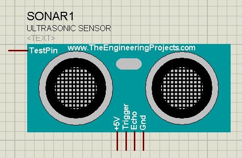
How the Ultrasonic Measurement Works
The transmitter emits an ultrasonic burst and the receiver detects reflected sound. For the familiar HC-SR04 interface, the controller starts a measurement through Trig and measures a pulse on Echo. The pulse width represents the sound's outward and return travel time. We divide by two because the required distance is only the outward journey.
The basic relationship is distance = speed of sound × elapsed time / 2. If we assume 343 m/s, equivalent to 0.0343 cm/µs, a 1,000 µs round trip corresponds to 17.15 cm. That is an illustrative calculation based on a chosen sound speed, not an exact calibration for every module or environment.
The HC-SR04 reference sheet describes a trigger pulse of at least 10 µs, an ultrasonic burst at 40 kHz and a suggested measurement interval greater than 60 ms. It also gives the convenient approximate conversion of echo microseconds divided by 58 for centimeters. Our example uses a 100 ms pause between measurements.
Why the simulated control is different
The extra analog pin replaces the physical environment as an input to this model. A variable voltage can represent a changing obstacle distance, allowing the same Arduino trigger-and-echo logic to be exercised repeatedly. It does not mean that a real ultrasonic sensor measures distance by reading a potentiometer.
Do not assume a universal volts-per-centimeter conversion for the control pin. The mapping belongs to the particular model implementation. Record the echo pulse width and reported distance at several control settings if you need to characterize your installed version. A model's control range and a physical sensor's usable acoustic range are separate properties.
Download the Ultrasonic Sensor Library
Use the original library download below. Extract the archive into a clearly named folder before copying files into Proteus. Keep a copy of the extracted package so you can identify which version is installed and restore it if necessary.
Ultrasonic Sensor Library for Proteus
The library described by this tutorial contains three files: UltrasonicTEP.IDX, UltrasonicTEP.LIB and UltrasonicTEP.HEX. The library files make the device available to Proteus, while the HEX file provides the behavior expected by this legacy model. All three belong to the sensor package.
| File | Where it is used | Purpose |
|---|---|---|
| UltrasonicTEP.LIB and UltrasonicTEP.IDX | Proteus library search location | Make the ultrasonic component available |
| UltrasonicTEP.HEX | Ultrasonic component's Program File property | Run the legacy sensor model |
| Your compiled Arduino HEX | Arduino Uno's Program File property | Trigger measurements and process Echo |
Loading the sensor HEX into the Arduino, or loading the Arduino sketch into the sensor, will not make the circuit work. There are two simulated devices with two different program roles. This distinction is especially useful when a project opens correctly but produces no meaningful output.
Install the Library in Proteus
- Close any simulation currently using the library.
- Extract the downloaded package and locate the three named files.
- Find the library directory used by your Proteus installation rather than assuming one fixed Windows path.
- Place the supplied library files there and keep the sensor HEX in an accessible, stable location.
- Restart Proteus or refresh its library availability as required by your version.
- Open the device picker and search for the ultrasonic component supplied by this package.
Proteus installation layouts can differ between versions and configured paths. Our guide to adding a Proteus library explains the general procedure. Keep custom files separate from unrelated built-in libraries and avoid overwriting another package just because it has a similar device name.
Place the sensor on the schematic after it appears in the picker. A visible symbol confirms that Proteus found the library definition, but it does not by itself establish that the behavior file is loaded. Labcenter's simulation-model overview provides useful context for the distinction between a component representation and a working simulation model.
Set the sensor's Program File
Open the ultrasonic component properties and browse to UltrasonicTEP.HEX in the Program File field. Use a path that remains valid after reopening the project. If you share the project folder, include the required file arrangement and update any absolute paths that refer to another computer.
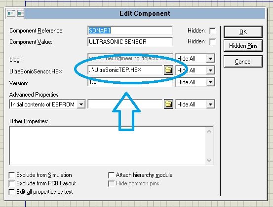
The retained properties screenshot shows this legacy configuration step. A newer or differently packaged sensor model might use another mechanism, so these instructions apply to the files named above. The original archive and images remain available; this refresh does not claim fresh compatibility testing across every Proteus release.
Components for the Arduino Example
We will use an Arduino Uno model, the ultrasonic component, a potentiometer or adjustable source for its simulation control, and the Proteus Virtual Terminal. The original component selection also included an LED. The distance-reading sketch below uses serial output; an extra LED is not required for the measurement itself.
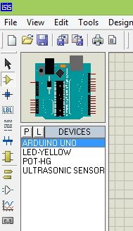
If your Arduino component is missing, install a compatible Arduino library for Proteus first. The Arduino model and ultrasonic model are separate packages. Finding one in the device picker does not install the other.
| Signal | Connection | Reason |
|---|---|---|
| Sensor Trig | Arduino D7 | Starts a measurement |
| Sensor Echo | Arduino D6 | Provides the pulse to measure |
| Sensor supply and ground | Appropriate modeled supply and common ground | Establishes the electrical references |
| Additional analog control | Variable source or potentiometer wiper | Sets the simulated environment |
| Arduino D1/TX | Virtual Terminal RXD | Displays the serial measurements |
Build the Proteus Circuit
Connect Trig and Echo exactly as listed, then establish a common ground between the Arduino and sensor model. For a potentiometer control, connect its ends to the model's intended control supply and ground, and connect the wiper to the extra analog input. Do not leave the input floating.
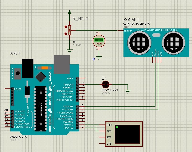
The original schematic illustrates the arrangement. Use the pin names on the component rather than relying on left-to-right position, since symbols can be rotated or revised. Keep the adjustable control voltage within the intended model range. This tutorial does not define behavior for arbitrary negative or excessive control voltages.
Set the Virtual Terminal to 9600 baud with the normal 8-bit, no-parity, one-stop-bit framing used by Serial.begin(9600). Arduino TX connects to terminal RXD. A reverse connection is unnecessary for this one-way output example because the sketch does not receive terminal commands.
For an introduction to the instrument, see How to Use the Virtual Terminal in Proteus. Terminal settings and the Arduino model clock must agree with the compiled program; otherwise the display can remain blank or show unreadable characters.
Arduino Code with an Explicit Echo Timeout
The original program measured Echo and printed inches and centimeters. The version below keeps that flow while adding a finite timeout and reporting an invalid measurement separately. This prevents a missing echo from being displayed as a real object at zero distance.
const byte triggerPin = 7;
const byte echoPin = 6;
const unsigned long echoTimeoutUs = 30000UL;

void setup() {
  pinMode(triggerPin, OUTPUT);
  pinMode(echoPin, INPUT);
  digitalWrite(triggerPin, LOW);
  Serial.begin(9600);
}

void loop() {
  digitalWrite(triggerPin, LOW);
  delayMicroseconds(2);
  digitalWrite(triggerPin, HIGH);
  delayMicroseconds(10);
  digitalWrite(triggerPin, LOW);

  unsigned long durationUs =
      pulseIn(echoPin, HIGH, echoTimeoutUs);

  if (durationUs == 0) {
    Serial.println("No valid echo");
  } else {
    float distanceCm = durationUs / 58.0f;
    float distanceInches = distanceCm / 2.54f;
    Serial.print("Echo: ");
    Serial.print(durationUs);
    Serial.print(" us | Distance: ");
    Serial.print(distanceCm, 1);
    Serial.print(" cm | ");
    Serial.print(distanceInches, 1);
    Serial.println(" in");
  }
  delay(100);
}
Understand the important lines
The pin directions are established once in setup. Trig begins low, receives a short high pulse and returns low. The program then measures how long Echo remains high. The unsigned-long type matches the timing result and avoids unnecessarily restricting the possible microsecond count.
Arduino's pulseIn documentation specifies a microsecond return value and a zero result when the pulse is not completed within the timeout. The explicit 30,000 µs timeout bounds the wait in this example. It does not extend the sensor's physical range or guarantee that every returned pulse is a valid acoustic measurement.
Using 58.0f keeps fractional centimeters instead of truncating each integer division. The output is printed to one decimal place for readability, but that formatting does not establish millimeter accuracy. Dividing centimeters by 2.54 keeps the two displayed units consistent.
A 5,800 µs pulse gives 100.0 cm by this approximation and approximately 39.4 inches. A 2,900 µs pulse gives 50.0 cm. These convenient values make useful reasoning checks when comparing a measured pulse with the terminal output.
Compile and Load the Arduino Firmware
Select the Arduino Uno board configuration in the Arduino IDE and compile the sketch for the processor and clock represented by the Proteus component. Export or locate the compiled application HEX using the supported workflow for your IDE version. Our Arduino HEX-file guide explains the purpose of that output.
Open the Arduino component properties and select that newly compiled program. Leave UltrasonicTEP.HEX assigned to the sensor. If you later edit the sketch, compile it again and ensure the Arduino points to the new output rather than an old copy in another folder.
Do not infer success merely from a successful sketch compilation. Compilation checks the program for its selected target. It does not confirm schematic wiring, a valid sensor model path or correct terminal settings.
Run the Simulation and Interpret the Results
Start the simulation and open the terminal. Change the analog control slowly and watch the reported echo duration and distance. When the model provides longer echo pulses, the calculated distance increases. The retained running screenshot shows the original example's serial measurements.
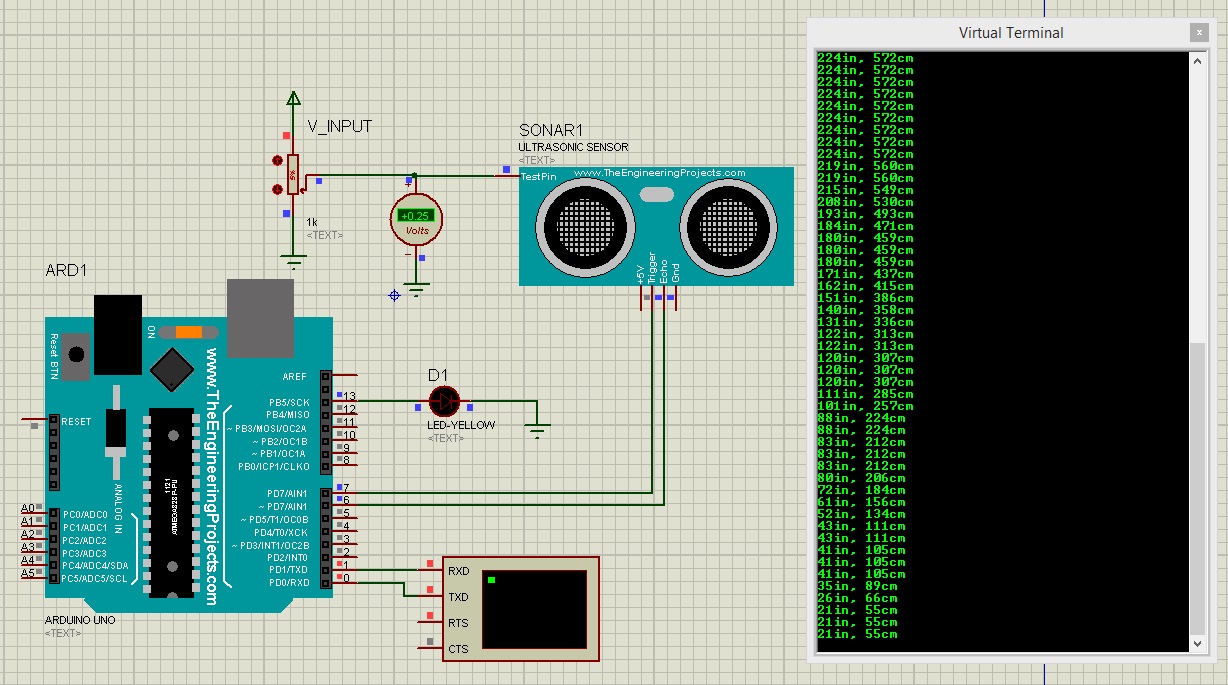
Use several stable control positions instead of moving continuously during every measurement. Record the control setting, measured pulse duration and calculated centimeters. This separates the model's input mapping from the arithmetic performed by Arduino and makes unexpected jumps easier to investigate.
The original project archive below contains its historical simulation, sketch and compiled files. It remains attached for continuity. Its code may differ from the timeout-aware example printed above; compile the revised sketch yourself if you want that behavior. The archive has not been silently replaced with a new build.
Download Code and Proteus Simulation
Simulation assumptions to remember
A variable voltage does not reproduce acoustic reflections, absorption or multiple objects. A stable simulated result therefore does not prove that a physical sensor will detect a narrow, angled or soft target at the same distance. Use the simulation to develop the electrical interface and program flow, then characterize the real application separately.
The 100 ms delay makes the example easy to follow but also makes it blocking. While waiting for Echo or sleeping between measurements, the loop cannot perform other normal loop work. Applications requiring simultaneous responsiveness may need a timed state machine or hardware capture approach.
Check units before interpreting accuracy
The approximate divisor of 58 represents a sound-speed convention. From d = ct/2, with d in centimeters and t in microseconds, the equivalent divisor is 20,000/c when c is expressed in meters per second. At 343 m/s, that divisor is about 58.31. Using 58 instead changes the numerical result slightly; it is not evidence that either the simulator or your ruler is broken.
For a 5,800 µs pulse, the 58 divisor gives 100 cm while 343 m/s gives 99.47 cm. This roughly half-percent difference comes from the assumed conversion alone. Physical uncertainty also includes the target, the sensor and environmental conditions. Reporting many decimal places cannot remove those sources of error.
Build a small measurement record
Choose five stable control positions spanning the useful simulated range. At each position, record several pulse widths before calculating an average. Keep timeout entries separate instead of averaging them as zero. Otherwise a missing reading would artificially pull the average toward the sensor.
For example, durations of 2,900, 2,900 and 2,958 µs correspond to 50, 50 and 51 cm with the selected divisor. Their mean is approximately 50.33 cm. If a fourth acquisition times out, the mean of the three valid values remains 50.33 cm and the record should also report one invalid acquisition.
This simple table helps answer two different questions: whether the model responds repeatably to its control input, and whether the program converts the returned timing correctly. If pulse widths change but displayed distance does not, inspect arithmetic and the loaded Arduino firmware. If neither changes, investigate the model control and wiring first. Keep the raw timing in diagnostic output until the interface is understood.
Troubleshooting the Library and Circuit
| Symptom | Check first |
|---|---|
| Sensor missing from the picker | Extracted files and the active Proteus library location |
| Symbol appears but has no behavior | Sensor Program File points to UltrasonicTEP.HEX |
| Terminal is blank | Arduino program path and D1/TX to RXD wiring |
| Unreadable serial text | Baud rate and modeled processor clock |
| No valid echo | Trig/Echo wiring and the sensor behavior file |
| Distance never changes | Analog control connection and actual wiper voltage |
When several things are wrong, fix one layer at a time. First establish that the Arduino can print a startup message. Then confirm the trigger signal, followed by the echo response. Only after those steps should you investigate distance conversion or application thresholds.
Related Examples and Further Practice
Continue with our button, proximity and switch simulation examples, then compare multiple-sensor interfacing. The original XBee home-automation project is another application context.
Other library tutorials remain useful when expanding a project: Genuino, GPS, GSM, XBee, PIR, Bluetooth and DS1307. Add components according to the actual task rather than installing every package at once.
Frequently Asked Questions
Why does the Proteus sensor have an extra analog pin?
It supplies the simulated environment to this model. A physical HC-SR04 has power, ground, trigger and echo connections; it does not use that extra control pin.
Do I need an Arduino ultrasonic library for this code?
No. The sketch uses standard Arduino digital I/O, timing and serial functions. The Proteus component library serves a different purpose from an Arduino source-code library.
Why does a timeout not mean zero centimeters?
A zero timing result means the program did not receive a complete pulse within its wait period. It is missing measurement information, not a confirmed obstacle at zero distance.
Can I connect a real HC-SR04 directly to a 3.3 V board?
Check the particular module and controller ratings. The conventional 5 V module's Echo output may require level shifting or a suitable divider before a 3.3 V input. A simulated connection does not establish hardware voltage compatibility.
Does this tutorial guarantee compatibility with every Proteus version?
No. It documents the original library package and setup. Model availability, installation paths and supported processor simulation depend on the installed software and license.