How to use Timer Interrupt in 8051 Microcontroller

Hello friends, hope you all are fine and having fun with your lives.In today's post, we are gonna see How to use timer interrupt in 8051 Microcontroller.8051 Microcontroller comes with timer as well. They normally have two timer in them named as Timer0 and Timer1. These timers are used for counting purposes like you want to start some countdown in your project then you can use these timers or you wanna create some clock then in that case as well you need timers. So, in short there are numerous uses of timers in a project. Timers are also used for delays like you wanna create some delay of 10 sec but you dont wanna use the delay function in your project so you can use timers. You start the timer and then when it comes to 10 seconds then you can do your work. So, these are different uses of a timer and clearly we can't neglect its importance, so today we are gonna see How to use these timer interrupt in 8051 Microcontroller.

Now coming towards interrupt, interrupt is interrupt :P Yeah really, we call it interrupt because its an interrupt. In programming codes there are many things which needs to run in background and appear when its time for them to appear. Here where interrupt comes handy. Interrupt is kind of a background code which keeps on running in the background while the main code keeps on running in front but when the interrupt condition is fullfilled then it interrupts the main program and executes the functions defined in it. For Timer interrupts, suppose I wanna blink my LED after every 2 seconds then what will I do is I will start a timer for 2 seconds and when this timer completes I will generate an interrupt. So, in this way after every two seconds the led will blink. So, let's start with timers interrupt in 8051 Microcontroller and see how we are gonna do this.

How to use Timer interrupt in 8051 Microcontroller ???

As I explained earlier, we are gonna use Timer interrupt in 8051 Microcontroller. so, now before gong into the details, let me first throw some light on how we are gonna implement this. Timers count from 0 to 255 in 8 bit mode as in 8 bit 255 is the maximum value and when timer hits the 255 number then we say that our timer is overflowed. Now when timer overflows, then it sends us a indication using which we generate our intterupt. In timers, there are few registers in which they store their value. If we are talking about Timer0 then timer0 stores its value in TL0 register. Now suppose I want my timer to start counting from 10 instead 0 then I will store 10 in my TL0 register and it will count from 10 instead 0 and when it reaches 255 it will overflow. Now when Timer0 will overflow then it will make TF0 bit HIGH. TF0 is another register value, if its 1 then it means that our timer is full and if its 0 then it means our timer is still counting. So, that's how we count from our timer and check the pin TF0. Now first of all, I am gonna use Timer0 and then we will have a quick look at Timer1.

Timer0 Interrupt
  • First of all, design a simple circuit as shown in below figure:
  • Now upload the below code in your Keil software and get the hex file.
#include<reg51.h>

// Out Pin
sbit Out = P2^0;		   // Pin P2.0 is named as Out

//Function declarations
void cct_init(void);
void InitTimer0(void);


int main(void)
{
   cct_init();   	       // Make all ports zero
   InitTimer0();           // Start Timer0
 
   while(1)                // Rest is done in Timer0 interrupt
   {
   }
}

void cct_init(void)
{
	P0 = 0x00;   
	P1 = 0x00;   
	P2 = 0x00;   
	P3 = 0x00;  
}


void InitTimer0(void)
{
	TMOD &= 0xF0;    // Clear 4bit field for timer0
	TMOD |= 0x02;    // Set timer0 in mode 2
	
	TH0 = 0x05;      // 250 usec reloading time
	TL0 = 0x05;      // First time value
	
	ET0 = 1;         // Enable Timer0 interrupts
	EA  = 1;         // Global interrupt enable
	
	TR0 = 1;         // Start Timer 0
}


void Timer0_ISR (void) interrupt 1   // It is called after every 250usec
{
	Out = ~Out;  // Toggle Out pin

	TF0 = 0;     // Clear the interrupt flag
}

  • In the above code, the main function is our InitTimer0 function.
  • In this function what I have done is I simply set the timer 0 to mode 2. In mode 2, it will auto reload means once the timer0 overflows then it will comes back to its original value and will start again.
  • TL0 has 0x05 in it which is the initial value of timer0 and it will count for 250 micro seconds.
  • TH0 also has the 0x05. On reload timer uploads the vlaue from TH0 into TL0 so thats why we have given the same value to TH0.
  • After that we make ET0 bit enabled which will enable the timer, if you dont set this pin HIGH then our timer will not work.
  • EA bit will enable the global interrupt. if we dont enable this pin then timer will work but it wont generate the interrupt.
  • Finally after setting all configurations, we started our timer.
  • Now when the Timer0 overflows after every 250 micro seconds, it will generate the interrupt and it will come to Timer0_ISR function.
  • In Timer0_ISR function, I simply toggled the OUt pin which is Pin2.0 and then I again set the interrupt bit to 0 which is TF0.
  • That's how our timer is working and if we check the P2.0 pin on oscilloscope then it will look something as shown in below figure:
  • You can see in the above figure that our pin is toggling with an interval of 250 usec.
  • One important thing to note is there's no function written in while(1) loop and still its working because its running on background and performing the interrupt routine. You can add any function in your MAin code and it will keep on working and meanwhile at the background your interrupt will also keep on generating.
  • You can download this Simulation and programming code by clicking on below button.

Download Timer0 Code and Simulation

  • Now, lets have a quick look on Timer1 interrupt in 8051 Microcontroller.
Timer1 Interrupt
  • Now let's have a quick look on Timer1 interrupt in 8051 Microcontroller. For that, design the same simulation in Proteus as we did for Timer 0.
  • Now, upload the below code in your Keil software and get the hex file.
#include<reg51.h>

// Out Pin
sbit Out = P2^0;		   // Pin P2.0 is named as Out

//Function declarations
void cct_init(void);
void InitTimer1(void);


int main(void)
{
   cct_init();   	       // Make all ports zero
   InitTimer1();           // Start Timer1
 
   while(1)                // Rest is done in Timer1 interrupt
   {
   }
}

void cct_init(void)
{
	P0 = 0x00;   
	P1 = 0x00;   
	P2 = 0x00;   
	P3 = 0x00;  
}


void InitTimer1(void)
{
	TMOD &= 0x0F;    // Clear 4bit field for timer1
	TMOD |= 0x20;    // Set timer1 in mode 2
	
	TH1 = 0x05;      // 250 usec reloading time
	TL1 = 0x05;      // First time value
	
	ET1 = 1;         // Enable Timer1 interrupts
	EA  = 1;         // Global interrupt enable
	
	TR1 = 1;         // Start Timer 1
}


void Timer1_ISR (void) interrupt 3   // It is called after every 250usec
{
	Out = ~Out;  // Toggle Out pin

	TF1 = 0;     // Clear the interrupt flag
}

  • Now you can see in the above code that its exactly the same as we used for Timer0 with a slight difference that now we are using registers for Timer1.
  • Instead of TL0, now we are using TL1 and similarly TH1 instead of TH0 and TR1 instead of TR0.
  • Rest of the code is exactly the same and hence it will give the same result as for Timer0 and is shown in below figure:
  • You can download the code for Timer1 along with simulation by clicking the below button.

Download Timer1 Code and Simulation

That's all for today, I hope you guys have got something out of today's post and gonna like this one. In the coming post, I am gonna design some simple project on 8051 Microcontroller in which I will use these Timers, then you will get know more about them. So, stay tuned and subscribe us by email. Take care !!! :)

8051 Microcontroller Projects

Hello everyone, hope you all are fine and having fun with your lives. Today, I am going to share 8051 Microcontroller Projects. Recently, I have shared quite a lot of tutorials on 8051 Microcontroller which are not much arranged as a whole. So, today, I thought to arrange all those tutorials and place them here so that you can get all of them quite easily. I will upload more 8051 Microcontroller Projects and I am gonna add their links in this post so stay subscribed to this post if you are interested in learning 8051 Microcontroller.

8051 Microcontroller, as we all know, is another Microcontroller series just like PIC Microcontroller or Arduino etc. The benefit of 8051 Microcontrollers is that they are quite cheap and easily available so if you are going to design some product then its better to use 8051 Microcontroller instead of PIC Microcontroller or Arduino etc. As they are cheap so they also come with a disadvantage which is that they are not much rich with features. Few of 8051 Microcontrollers doesn't even support Serial Communication. So, before choosing it for your project, must check their datasheet to confirm that they are suitable for your projects.

In most of these below projects, I have designed the complete simulation in Proteus and the code is also given but my suggestions is don't simply download the simulation and run it. Instead design the simulation from scratch and then design your code and run the simulation on your own. Consider my codes and simulations as a guide but dont get dependent on them as then you are not gonna get anything. Anyways let's get started with 8051 Microcontroller Projects.

8051 Microcontroller Projects

Below are mentioned all the 8051 Microcontrollers Projects, which I have shared on this blog. You can check these projects and can also download their simulations designed in Proteus. I have given codes for most of these projects but few are paid, which you can buy from our shop at a quite minimal rate.

Basic Projects

These are basic projects and are best for beginner level programmers. If you are new to 8051 Microcontroller then first read these projects. These all projects contain complete codes as well as the Proteus simulation so you can quite easily test them in Proteus software and can edit the codes and learn from it.

Intermediate Projects

These are Intermediate level 8051 Microcontroller Projects. If you wanna do these projects then you must first learn or atleast have a look at basic 8051 Microcontroller projects as they are using same components as we interfaced in basic level. If you feel any problem then ask in comments.

That's all for today, but I am gonna add more projects in it and will keep on updating the list. Subscribe us and get these exciting tutorials straight to your mail box.

XBee Library for Proteus

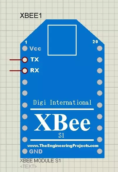
Hello everyone, today I am going to share a new XBee Library for Proteus. I am quite excited while sharing it as we are the first developer for this XBee Library. Now you can quite easily use XBee module in your Proteus software using this XBee Library for Proteus.Wehave spent quite a lot of time in developing this and that's the reason I couldn't share new tutorials in the past few days. Anyways we are done with this new exciting XBee Library for Proteus, hope you are gonna enjoy this one. I have already sharede two libraried for Proteus which are Arduino Library for Proteus and GPS Library for Proteus. You can also interface this XBee module with Microcontrollers like Arduino, PIC Microcontroller and 8051 Microcontroller quite easily.

As its the first version of our XBee Library for Proteus so its not quite perfect and can't do the complex tasks such as analog inputs etc. It will just do the serial communication. This xbee module has two pins TX and RX and you can do your communication with it quite easily. We have designed this XBee Library for Proteus, after quite a lot of effort and we are quite proud that we are presenting it first time for Proteus. Other bloggers are welcome to share this library on their blogs to share the knowledge but do mention our blog post link in your post. :) You should also have a look at XBee Arduino Interfacing. So, let's get started with it.

XBee Library for Proteus

  • First of all, download this XBee Library for Proteus by clicking on the below button:
XBee Library for Proteus

  • Now once you click it you will get a zip file to download so download this zip and open it.
  • In this zip file you will get two files named as:
    • XBeeTEP.LIB
    • XBeeTEP.IDX
  • So, now place these two files in the libraries folder of your Proteus software.
Note:
  • Now, start your Proteus ISIS software or restart it if its already running.
  • Go to your components library and search for XBee Module as shown in below figure:
  • Now place it in your workspace and it will look something as shown in below figure:
  • If you don't know much about xbee module then you should also have a look at Introduction to XBee Module.
  • As you can see in the above figure, its our xbee module in Proteus for the first time.
  • As, I mentioned earlier, its a first version of xbee module so its not very advanced and it will do just the basic serial communication i.e. sending and receiving data.
  • It has two pins on it which are TX and RX and using these two pins you can send and receive data quite easily.
  • So, let's design a simple example and we will see How to do the Serial communication using this new XBee library for Proteus.
  • Design a simple circuit as shown in below figure:
  • Now what I did is, I simply place a Virtual terminal with both of these xbee modules.
  • Now we need to change the Properties of one of these XBee module so double click on any one of these and you will get the below window:
  • You should also have a look at Interfacing of XBee with Computer.
  • Now, I have simply changed the Physical Port of this module to COM2 while the other module is at COM1.
  • So, now one of my XBee module is at COM1 while the second module is at COM2.
  • Now when I run my simulation then both XBee will start sending and receiving data on their respective COM Ports.
  • So, what I need to do is to virtually combine these two ports and for that I have used a software named as Virtual Software Driver from Eltima and I combine these two ports.
  • Now, run your simulation and whatever you type in the Virtual Terminal of first xbee will appear in the virtual terminal of second xbee. as shown in below figure:
  • You can also interface this XBee modue with other microcontrollers like Arduino, PIC Microcontrollers or 8051 Microcontrollers etc.
  • I have explained this whole tutorial in below video as well.
I hope you have enjoyed it and are gonna like it. Let me know if you got into any trouble and have problems in using this library. Also share your suggestions about improvement in this XBee Library for Proteus. :)

GPS Library for Proteus

Hello friends, hope you all are fine and having fun with your lives. In today's tutorial, I am gonna share another awesome library designed by our team for Proteus, which is GPS Library for Proteus. It's my second library for Proteus, the first one was Arduino Library for Proteus which I have already shared. I am really enjoying designing these modules in Proteus because its a new and quite challenging thing. I haven't found even a single website who has designed these modules in Proteus already. So, now for the first time, you can have the GPS Library for Proteus using which you can easily simulate your GPS module in Proteus and can design your code for Arduino, PIC Microcontroller or 8051 Microcontroller.

Other bloggers are welcome to share this library and its my humble request that do mention our blog in credits. :) The GPS module, I have designed for Proteus is a simple GPS which has TX and RX pins and when you start the simulation, this module starts sending the NMEA data on its TX pin, which you can easily check using Virtual Terminal. I am gonna show you how to check it in today's post. Another important thing, obviously in Proteus Simulation we can't get the actual values of longitude,latitude etc, so in our model, I have used the dummy values for all these data. The benefit of this module is that you can easily design your code for GPS and can test it in your simulation. Plus, its design is cool as well. ;)

Note:

GPS Library for Proteus

  • First of all, click on the below button and download GPS Library for Proteus.
GPS Library for Proteus
  • After downloading, you will get a zip file containing three files in it.
  • Now extract all these three files named as:
    • GpsTEP.LIB
    • GpsTEP.IDX
    • GpsTEP.HEX
  • Place these files in Libraries folder of your Proteus software.
Note:
  • Now open your Proteus software, if you have already opened it then restart your Proteus software.
  • Now in components list search for GPS Module and place it in your workspace.
  • If everything's fine then you will get your module as shown in below figure:
  • As you can see in the above figure, it has two pins in total which are TX and RX.
  • Now double click this GPS module and you will get to its properties as shown in below figure:
  • Now, one last thing you need to do is to upload the GpsTEP.HEX file, which you got in the downloaded zip file, in the Program File section.
  • This GpsTEP.HEX file is essential for this model as its adding the functionality of GPS in this model.
  • So, after adding the link of GpsTEP.HEX file in the Program File section, now your Gps module is ready to use in your circuit.
  • So, now let's add a Virtual terminal and check the output of this GPS Module. If you haven't worked on Virtual Terminal before then you should read How to use Virtual Terminal in Proteus ISIS.
  • Design a small circuit as shown in below figure:
Note:
  • The baud rate of this GPS Module is 9600.
  • The data sent by this GPS module is dummy as we can't get these values in simulation.
  • Now let's run the simulation and check the Virtual Terminal and if everything goes fine then you will get results as shown in below figure:
  • The first line is just the intro for this module and after that you will start receiving data which is in NMEA format.
  • NMEA data will remain constant but will keep on coming.
  • Now, instead of using this Virtual Terminal, you can use any microcontroller here like Arduino, PIC Microcontroller or 8051 Microcontroller etc. and can write your code easily and test it.
  • In my coming tutorials, I am gonna share examples for this GPS module in which I will interface it with different Microcontroller.
  • In the below video, I have explained this tutorial again so if you got any trouble then watch it as well.
That's all for today. You should also have a look at Interfacing of GPS Module with Arduino in Proteus ISIS. I hope you guys have enjoyed today's post and are gonna get benefit from it. Let me know your views about today's tutorial and also give your suggestions and help us in making this GPS Library for Proteus more smarter. :)

Seven Segment Display with 8051 Microcontroller

Hello friends, I hope you all are fine and having fun with your lives. In today's post, we are gonna have a look at How to interface Seven Segment display with 8051 Microcontroller. Seven Segment Display is normally used in those projects where counting or clock functionalities are required. If you wanna read the basic details of Seven Segment Display then must read Interfacing of Seven Segment Display with Arduino, I have explained 7 Segment Display in detail in that tutorial. And have also interfaced it with Arduino board. So, I am not gonna go into the details of 7 Segment in today's tutorial and I would recommend you to must read this tutorial.

As 8051 Microcontroller is concerned, we all know that Its a Microcontroller in which we program our code and make it work. The 8051 microcontroller, I have used in this post is AT89C51. I have also designed this project on hardware and have tested code and it works fine. The crystal oscillator I have used in this project is of 16MHz. You can also download the Proteus Simulation along with programming code and hex file designed in keil uvision 3, at the end of this post. So, now let's get started with it. You may also wanna read the below projects on 8051 Microcontroller:

Interfacing of Seven Segment Display with 8051 Microcontroller

  • Seven Segment Display is of two types which is common cathode and common anode.
  • In this post, I have used common anode but you can easily use this code for common cathode but you have to do small change in the hardware.
  • If you are using common cathode then instead of GND you have to give +5V to the Seven Segment Display.
  • So, now let's first design the Proteus Simulation of Seven Segment Display with 8051 Microcontroller.
Proteus Simulation
  • First of all, design a Proteus Simulation for Interfacing of Seven Segment Display with 8051 Microcontroller,as shown in below figure:
  • Now you can see in the above figure that I have used 8051 Microcontroller which is AT89C51.
  • I have used Seven Segment display which is of Red color.
  • It has total 8 pins so we have connected these 8 pins of Seven Segment Display to 8 pins of Port 2 of 8051 Microcontroller.
  • Now, the last thing, I have used is 74LS245. Its kind of a current amplifier. 8051 Microcontroller provides quite small current on its output pins which is not quite enough for the Seven Segment Display to turn its LEDs ON.
  • So, we used this 74LS245 which provides extra current and makes the Seven Segment Display to work properly.
  • Now, let's design the programming code for this project.
Programming Code
  • I have designed the programming code for interfacing of Seven Segment Display with 8051 Microcontroller in Keil uvision 3 compiler.
  • The programming code is as follows:
#include<reg51.h>

void cct_init(void);
void delay(int);
void DisplayOn7Segment(char);

int main(void)
{
   char ch = '0';	          // Character to be displayed on 7seg

   cct_init();   	          // Make all ports zero	

   while(1)           
   {
	DisplayOn7Segment(ch);	  // Display ch on 7seg
	delay(30000);			  // About 1 sec delay

	switch(ch)				  // Update ch with new value to be displayed
	{
		case '0':	ch = '1';  break;
		case '1':	ch = '2';  break;
		case '2':	ch = '3';  break;
		case '3':	ch = '4';  break;
		case '4':	ch = '5';  break;
		case '5':	ch = '6';  break;
		case '6':	ch = '7';  break;
		case '7':	ch = '8';  break;
		case '8':	ch = '9';  break;
		case '9':	ch = '0';  break;
	
	
		default: ch = '0';  break;
	}
   }
}

void cct_init(void)
{
	P0 = 0x00;   
	P1 = 0x00;   
	P2 = 0x00;   
	P3 = 0x00;  
}

void delay(int a)
{
   int i;
   for(i=0;i<a;i++);   //null statement
}

void DisplayOn7Segment(char ch)   // ch can have a value from '0' to 'F' only
{
	switch(ch)
	{
		case '0':	P2 = 0x3F;  break;
		case '1':	P2 = 0x06;  break;
		case '2':	P2 = 0x5B;  break;
		case '3':	P2 = 0x4F;  break;
		case '4':	P2 = 0x66;  break;
		case '5':	P2 = 0x6D;  break;
		case '6':	P2 = 0x7D;  break;
		case '7':	P2 = 0x07;  break;
		case '8':	P2 = 0x7F;  break;
		case '9':	P2 = 0x6F;  break;
	

		default: P2 = 0x3F;  break;
	}	
}
  • Now the code code is quite simple. I have added a small delay of 1 second and then displayed the character and stored the next character in array.
  • So, in this way we are displaying the characters from 0 to 9 and then repeats the process.
  • Now, you have seen the basics of Seven Segment Display with 8051 Microcontroller and now you can design any kind of project on it, like you can create a counter or a timer.
  • Now, compile the code and get the hex file and upload it to your 8051 Microcontroller and run the simulation.
  • If everything goes fine then you will get the results as shown in below figure:
  • You can download the Programming code and Simulation for interfacing of Seven Segment Display with 8051 Microcontroller, by clicking on the below button.

Download Simulation and Code

That's all for today, I hope now you can quite easily interface this seven segment display with 8051 Microcontroller. In the next post, we will have a look at some new project with 8051 Microcontroller. So, till then take care and have fun !!! :)

Design a Simple Calculator with 8051 Microcontroller

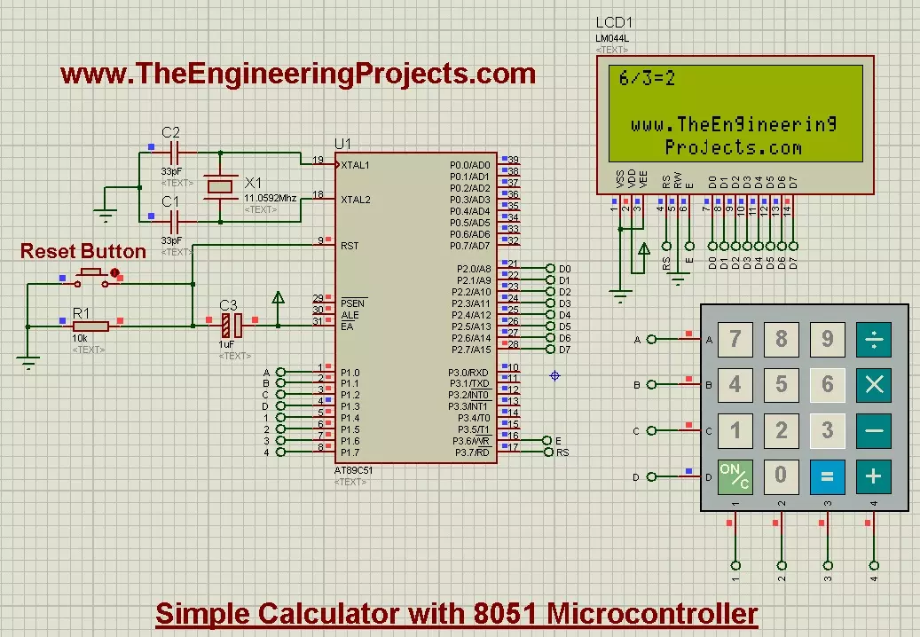
Hello friends, today's post is about designing a simple calculator with 8051 Microcontroller. In our previous post, we have seen How to Interface keypad with 8051 Microcontroller in Proteus ISIS. Moreover, we have also worked on Interfacing of LCD with 8051 Microcontroller in Proteus ISIS. If you haven't read these two posts then my suggestion is to read them first before going into the details of this post, as we are going to use both keypad and LCD in order to design the simple calculator with 8051 Microcontroller.

Actually we have already understood the working of both keypad and LCD so I thought to share this small project as it will give you the practical application of both keypad and LCD. And if you are new to 8051 Microcontroller then its always better to first design a small project and then move to pro one. The Simulation file along with hex file and complete code is given at the end for download. But my suggestion is to design it by yourself as it will help you in learning. You will do mistakes but obviously it will help you in learning so make mistakes and learn with it. So, let's get started with it.

Design a Simple Calculator with 8051 Microcontroller

  • The calculator we are going to design in this post is quite basic calculator, it will only perform 4 tasks, which are as follows:
    • When you press the (+) button then it will add the two digits. For example, you want to add 2 and 3 then you need to press 2 + 2 = these four buttons in sequence and when you press the = button it will automatically will give you the sum.
    • When you press (-) button it will subtract the two digits like 3 - 2 = and it will give you the result.
    • When you press (x) button it will multiply the two digits.
    • When you press the (/) button it will simply divide the two digits.
  • Whenever you press the (=) button, it will give you the output depending on the function you used before and if you press (=) in the start then it will give "Wrong Input".
  • Finally, there's (ON/C) button on the Calculator, when you press this it will simply reset the code and will clear the LCD.
  • So, that's how this calculator is gonna work. Moreover, it will always reset when you try to calculate new value.
  • As its a simple calculator, so its only limited to 1 digit, means it will only apply the operation on single digit input like 2+3 but it won't work on more than 1 digit like 12 + 13.
  • I will soon design a more complicated calculator but for this one its only limited to single digit.
  • So, now let's design this calculator, so first we are gonna have a look at the Proteus simulation of Simple calculator with 8051 Microcontroller.
  • After that, we will do the coding part for calculator with 8051 Microcontroller.
  • So, now let's get started with Proteus Simulation.
Proteus Simulation
  • So, you can see we have used the same LCD which is 20x4 and have used the same keypad as did in previous tutorial.
  • You can see this keypad has all the required operations for this project which are (+), (-), (x) and (/).
  • So, now let's have a look at the programming code for calculator with 8051 Microcontroller.
Programming Code
  • We have already seen the programming code for keypad and LCD and I am assuming that you have also read those posts so I am not going into the details of those posts.
  • So,we know that how to print data on LCD and we are also aware of how to get key press from keypad and then display it on LCD.
  • So, now let's move on to adding these functions.
while(1)
   { 
     //get numb1
     key = get_key();
     writecmd(0x01);            //clear display
	 writedata(key);            //Echo the key pressed to LCD
	 num1 = get_num(key);       //Get int number from char value, it checks for wrong input as well
     
	 if(num1!=Error)            //if correct input then proceed, num1==Error means wrong input
	 {
		 //get function
		 key = get_key();
		 writedata(key);                  //Echo the key pressed to LCD
		 func = get_func(key);            //it checks for wrong func
		 
		 if(func!='e')                    //if correct input then proceed, func=='e' means wrong input
		 {
			 //get numb2
			 key = get_key();
			 writedata(key);              //Echo the key pressed to LCD
			 num2 = get_num(key);         //Get int number from char value, it checks for wrong input as well
			 
			 if(num2!=Error)              //if correct input then proceed, num2==Error means wrong input
			 {
				 //get equal sign
				 key = get_key();
				 writedata(key);          //Echo the key pressed to LCD
				 
				 if(key == '=')           //if = is pressed then proceed
				 {
					 switch(func)         //switch on function
					 {
					 case '+': disp_num(num1+num2); break;
					 case '-': disp_num(num1-num2); break;
					 case 'x': disp_num(num1*num2); break;
					 case '/': disp_num(num1/num2); break;
					 }
				 }
				 else				      //key other then = here means error wrong input
				 { 
					 if(key == 'C')       //if clear screen is pressed then clear screen and reset
						writecmd(0x01);   //Clear Screen
					 else
						DispError(0); 	  //Display wrong input error
				 }                                 
			 }
		 }
     }
   }
  • As you can see in the above function, I have first check for the first key press.
  • When you pressed the first key on keypad then I get this key and converter it to integer.
  • After that I waited for the next key which must be some operation key like + - X or / otherwise it will generate the error message.
  • After that code is waiting for the third key which should be some numerical digit and then I converter it to integer again and if you entered some invalid key then it will generate the error.
  • Finally waiting for the = sign. When you press the = sign it will automatically perform the required operation which I placed in the switch case loop.
  • It will calculate the value and then print out the result and on next key press it will first clear the screen and then get the value and will continue.
  • Below is the detailed code for the project with comments and I hope you wont get into any trouble and will get it clearly.
#include<reg51.h>
#include<string.h>

//Define Macros
#define Error  13    // Any value other than 0 to 9 is good here

//Function declarations
void cct_init(void);
void delay(int);
void lcdinit(void);
void writecmd(int);
void writedata(char);
void writeline(char[]);
void ReturnHome(void);
char READ_SWITCHES(void);
char get_key(void);
int get_num(char);
char get_func(char);
void DispError(int);
void disp_num(int);
void WebsiteLogo();

//*******************
//Pin description
/*
P2 is data bus
P3.7 is RS
P3.6 is E
P1.0 to P1.3 are keypad row outputs
P1.4 to P1.7 are keypad column inputs
*/
//********************
// Define Pins
//********************
sbit RowA = P1^0;     //RowA
sbit RowB = P1^1;     //RowB
sbit RowC = P1^2;     //RowC
sbit RowD = P1^3;     //RowD

sbit C1   = P1^4;     //Column1
sbit C2   = P1^5;     //Column2
sbit C3   = P1^6;     //Column3
sbit C4   = P1^7;     //Column4

sbit E    = P3^6;     //E pin for LCD
sbit RS   = P3^7;     //RS pin for LCD

// ***********************************************************
// Main program
//
int main(void)
{
   char key;                     //key char for keeping record of pressed key
   int num1 = 0;                 //First number
   char func = '+';              //Function to be performed among two numbers
   int num2 = 0;                 //Second number
   
   cct_init();                   //Make input and output pins as required
   lcdinit();                    //Initilize LCD
   WebsiteLogo();
   while(1)
   { 
     WebsiteLogo();
     //get numb1
     key = get_key();
     writecmd(0x01);            //clear display
	 WebsiteLogo();
	 writedata(key);            //Echo the key pressed to LCD
	 num1 = get_num(key);       //Get int number from char value, it checks for wrong input as well
     
	 if(num1!=Error)            //if correct input then proceed, num1==Error means wrong input
	 {
		 //get function
		 key = get_key();
		 writedata(key);                  //Echo the key pressed to LCD
		 func = get_func(key);            //it checks for wrong func
		 
		 if(func!='e')                    //if correct input then proceed, func=='e' means wrong input
		 {
			 //get numb2
			 key = get_key();
			 writedata(key);              //Echo the key pressed to LCD
			 num2 = get_num(key);         //Get int number from char value, it checks for wrong input as well
			 
			 if(num2!=Error)              //if correct input then proceed, num2==Error means wrong input
			 {
				 //get equal sign
				 key = get_key();
				 writedata(key);          //Echo the key pressed to LCD
				 
				 if(key == '=')           //if = is pressed then proceed
				 {
					 switch(func)         //switch on function
					 {
					 case '+': disp_num(num1+num2); break;
					 case '-': disp_num(num1-num2); break;
					 case 'x': disp_num(num1*num2); break;
					 case '/': disp_num(num1/num2); break;
					 }
				 }
				 else				      //key other then = here means error wrong input
				 { 
					 if(key == 'C')       //if clear screen is pressed then clear screen and reset
					 {
					    writecmd(0x01);   //Clear Screen
						WebsiteLogo();
					 }
					 else
					 {
					 	DispError(0); 	  //Display wrong input error
						WebsiteLogo();
					 }
				 }                                 
			 }
		 }
     }
   }
}

void WebsiteLogo()
{
   writecmd(0x95);
   writedata('w');                                 //write
   writedata('w');                                 //write
   writedata('w');                                 //write
   writedata('.');                                 //write
   writedata('T');                                 //write
   writedata('h');                                 //write
   writedata('e');                                 //write
   writedata('E');                                 //write
   writedata('n');                                 //write
   writedata('g');                                 //write
   writedata('i');                                 //write
   writedata('n');                                 //write
   writedata('e');                                 //write
   writedata('e');                                 //write
   writedata('r');                                 //write
   writedata('i');                                 //write
   writedata('n');                                 //write
   writedata('g');                                 //write
 
   writecmd(0xd8);
 
   writedata('P');                                 //write
   writedata('r');                                 //write
   writedata('o');                                 //write
   writedata('j');                                 //write
   writedata('e');                                 //write
   writedata('c');                                 //write
   writedata('t');                                 //write
   writedata('s');                                 //write
   writedata('.');                                 //write
   writedata('c');                                 //write
   writedata('o');                                 //write
   writedata('m');                                 //write
   writecmd(0x80);
}

void cct_init(void)
{
	P0 = 0x00;   //not used
	P1 = 0xf0;   //used for generating outputs and taking inputs from Keypad
	P2 = 0x00;   //used as data port for LCD
	P3 = 0x00;   //used for RS and E   
}

void delay(int a)
{
   int i;
   for(i=0;i<a;i++);   //null statement
}

void writedata(char t)
{
   RS = 1;             // This is data
   P2 = t;             //Data transfer
   E  = 1;             // => E = 1
   delay(150);
   E  = 0;             // => E = 0
   delay(150);
}


void writecmd(int z)
{
   RS = 0;             // This is command
   P2 = z;             //Data transfer
   E  = 1;             // => E = 1
   delay(150);
   E  = 0;             // => E = 0
   delay(150);
}

void lcdinit(void)
{
  ///////////// Reset process from datasheet /////////
     delay(15000);
   writecmd(0x30);
     delay(4500);
   writecmd(0x30);
     delay(300);
   writecmd(0x30);
     delay(650);
  /////////////////////////////////////////////////////
   writecmd(0x38);    //function set
   writecmd(0x0c);    //display on,cursor off,blink off
   writecmd(0x01);    //clear display
   writecmd(0x06);    //entry mode, set increment
}

void ReturnHome(void)     /* Return to 0 cursor location */
{
   writecmd(0x02);
   delay(1500);
   WebsiteLogo();
}

void writeline(char Line[])
{
   int i;
   for(i=0;i<strlen(Line);i++)
   {
      writedata(Line[i]);     /* Write Character */
   }
   
   ReturnHome();          /* Return to 0 cursor position */
}

char READ_SWITCHES(void)	
{	
	RowA = 0; RowB = 1; RowC = 1; RowD = 1; 	//Test Row A

	if (C1 == 0) { delay(10000); while (C1==0); return '7'; }
	if (C2 == 0) { delay(10000); while (C2==0); return '8'; }
	if (C3 == 0) { delay(10000); while (C3==0); return '9'; }
	if (C4 == 0) { delay(10000); while (C4==0); return '/'; }

	RowA = 1; RowB = 0; RowC = 1; RowD = 1; 	//Test Row B

	if (C1 == 0) { delay(10000); while (C1==0); return '4'; }
	if (C2 == 0) { delay(10000); while (C2==0); return '5'; }
	if (C3 == 0) { delay(10000); while (C3==0); return '6'; }
	if (C4 == 0) { delay(10000); while (C4==0); return 'x'; }
	
	RowA = 1; RowB = 1; RowC = 0; RowD = 1; 	//Test Row C

	if (C1 == 0) { delay(10000); while (C1==0); return '1'; }
	if (C2 == 0) { delay(10000); while (C2==0); return '2'; }
	if (C3 == 0) { delay(10000); while (C3==0); return '3'; }
	if (C4 == 0) { delay(10000); while (C4==0); return '-'; }
	
	RowA = 1; RowB = 1; RowC = 1; RowD = 0; 	//Test Row D

	if (C1 == 0) { delay(10000); while (C1==0); return 'C'; }
	if (C2 == 0) { delay(10000); while (C2==0); return '0'; }
	if (C3 == 0) { delay(10000); while (C3==0); return '='; }
	if (C4 == 0) { delay(10000); while (C4==0); return '+'; }

	return 'n';           	// Means no key has been pressed
}

char get_key(void)           //get key from user
{
	char key = 'n';              //assume no key pressed

	while(key=='n')              //wait untill a key is pressed
		key = READ_SWITCHES();   //scan the keys again and again

	return key;                  //when key pressed then return its value
}

int get_num(char ch)         //convert char into int
{
	switch(ch)
	{
		case '0': return 0; break;
		case '1': return 1; break;
		case '2': return 2; break;
		case '3': return 3; break;
		case '4': return 4; break;
		case '5': return 5; break;
		case '6': return 6; break;
		case '7': return 7; break;
		case '8': return 8; break;
		case '9': return 9; break;
		case 'C': writecmd(0x01); return Error; break;  //this is used as a clear screen and then reset by setting error
		default: DispError(0); return Error; break;     //it means wrong input
	}
}

char get_func(char chf)            //detects the errors in inputted function
{
	if(chf=='C')                   //if clear screen then clear the LCD and reset
	{ 
		writecmd(0x01);            //clear display
		WebsiteLogo();
		return 'e'; 
	}
	
	if( chf!='+' && chf!='-' && chf!='x' && chf!='/' )  //if input is not from allowed funtions then show error
	{ 
		DispError(1); 
		WebsiteLogo();
		return 'e'; 
	}

	return chf;                        //function is correct so return the correct function
}


void DispError(int numb)           //displays differet error messages
{
	writecmd(0x01);                //clear display
	WebsiteLogo();
	switch(numb)
	{
	case 0: 	writeline("Wrong Input");      break;
	case 1: 	writeline("Wrong Function");   break;
	default:    writeline("Wrong Input");      break;
	}
}

void disp_num(int numb)            //displays number on LCD
{	
	unsigned char UnitDigit  = 0;  //It will contain unit digit of numb
	unsigned char TenthDigit = 0;  //It will contain 10th position digit of numb

	if(numb<0)
	{
		numb = -1*numb;  // Make number positive
		writedata('-');	 // Display a negative sign on LCD
	}

	TenthDigit = (numb/10);	          // Findout Tenth Digit

	if( TenthDigit != 0)	          // If it is zero, then don't display
		writedata(TenthDigit+0x30);	  // Make Char of TenthDigit and then display it on LCD

	UnitDigit = numb - TenthDigit*10;

	writedata(UnitDigit+0x30);	  // Make Char of UnitDigit and then display it on LCD
}

  • The above code is quite self explanatory and the main part I have already explained but still if you get into any troubled then ask in comments and I will resolve them.
  • Now copy this code in your keil uvision 3 and get the hex file.
  • Upload your hex file in Proteus ISIS and run your simulation.
  • The first screen you will get is as follows, which obviously displays our website address :P
  • Now, let's add 3 + 5 and we will get as shown in below figure:
  • Next operation, we are gonna do is the subtract one, so lets do this operation 3-9 = , shown below:
  • Now, lets do the third operation which is multiplication, so let's do this operation 9x9, shown below:
  • Now, finally do the last operation which is division, so I did 6/3 and result is shown below:
  • So, all the operations are shown in above figures, now if you give it wrong number like 2 digit number then it will display error message, as shown below:
  • It has become quite a lengthy post, so let's have the ending part. :)
  • You can download the Proteus Simulation along with hex file and code by clicking the below button.
Download Proteus Simulation and Code

So, that's all with the designing of simple Calculator with 8051 Microcontroller. I will try to work on advanced calculator, if I got time but I am not sure of that. :) So, that's all for today and will meet in next tutorial soon. till than have fun. !!! :)

Interfacing of Keypad with 8051 Microcontroller in Proteus

Hello friends, in today's post we are gonna have a look at Interfacing of Keypad with 8051 Microcontroller in Proteus ISIS. In the previous project, we have seen the Interfacing of LCD with 8051 Microcontroller and I have told there that LCD is a great debugging tool as we can print our data on it and can display different values and that's what is gonna done in today's post. Today, I will get the values from keypad and then question is how to know that we are getting the correct values. So in order to do so, we will display these values over LCD. So, that's how we are gonna use LCD as a debugging tool. As the debugging is concerned, there's another great tool for debugging which is called Serial port, we can also display these values over to Serial port. So, you should also read Serial communication with 8051 Microcontroller in Proteus ISIS, and try to display these keypad characters over to Serial port as a homework.

Anyways, let's come back to keypad, if you wanna read the keypad details then you should read Interfacing of keypad with Arduino in Proteus ISIS as I have mentioned all the basic details about keypad in that tutorial and I am not gonna repeat it. But as a simple recall, keypad works on matrix system like it has 4 columns and 4 rows so we will have total 8 pins through which we are gonna control these 16 buttons.  So, let's get started with it.

Interfacing of Keypad with 8051 Microcontroller in Proteus ISIS

  • Keypad is quite an easy and basic tool in embedded projects which is used in almost every kind of engineering project.
  • Today, we will first design the Proteus Simulation and after that we will design the programming code for 8051 Microcontroller.
  • The 8051 Microcontroller I have used is AT89C51 while the compiler I used for this microcontroller is keil uvision 3 and the simulation is designed in Proteus ISIS.
  • So, let's get started with Proteus simulation:
Proteus Simulation
  • Get the below components from Proteus components library and place it in your workspace.
  • Now design a circuit in Proteus software as shown in below figure:
  • Now as you can see in the above figure, I have used 4x4 keypad which has 4 rows and 4 columns and that's why there are total 16 buttons on it.
  • So, I have connected 8 pins of keypad with Port 1 of 8051 microcontroller.
  • LCD data pins are connected with Port 2 while the RS and E pins are connected to Port 3.
  • So, now let's move to the programming code for Interfacing of keypad with 8051 Microcontroller.
Programming Code
  • For programming purposes I have used Keil uvision 3 Compiler.
  • Most of the code is quite similar to that for Interfacing of LCD with 8051 Microcontroller, so if you wanna read about that then read this post.
  • The new code added in this post is about keypad which is as follows:
char READ_SWITCHES(void)	
{	
	RowA = 0; RowB = 1; RowC = 1; RowD = 1; 	//Test Row A

	if (C1 == 0) { delay(10000); while (C1==0); return '7'; }
	if (C2 == 0) { delay(10000); while (C2==0); return '8'; }
	if (C3 == 0) { delay(10000); while (C3==0); return '9'; }
	if (C4 == 0) { delay(10000); while (C4==0); return '/'; }

	RowA = 1; RowB = 0; RowC = 1; RowD = 1; 	//Test Row B

	if (C1 == 0) { delay(10000); while (C1==0); return '4'; }
	if (C2 == 0) { delay(10000); while (C2==0); return '5'; }
	if (C3 == 0) { delay(10000); while (C3==0); return '6'; }
	if (C4 == 0) { delay(10000); while (C4==0); return 'x'; }
	
	RowA = 1; RowB = 1; RowC = 0; RowD = 1; 	//Test Row C

	if (C1 == 0) { delay(10000); while (C1==0); return '1'; }
	if (C2 == 0) { delay(10000); while (C2==0); return '2'; }
	if (C3 == 0) { delay(10000); while (C3==0); return '3'; }
	if (C4 == 0) { delay(10000); while (C4==0); return '-'; }
	
	RowA = 1; RowB = 1; RowC = 1; RowD = 0; 	//Test Row D

	if (C1 == 0) { delay(10000); while (C1==0); return 'C'; }
	if (C2 == 0) { delay(10000); while (C2==0); return '0'; }
	if (C3 == 0) { delay(10000); while (C3==0); return '='; }
	if (C4 == 0) { delay(10000); while (C4==0); return '+'; }

	return 'n';           	// Means no key has been pressed
}
  • In the above function, which is READ_SWITCHES(), what we are doing is we are first checking the rows and after that for each row we are checking the columns.
  • For example, if you have pressed the button "1" then it will detect that first ROW and the first COLUMN has gone LOW and it will print out 1 as shown in above code.
  • That's how its reading all the 16 buttons, first detecting the Rows and then for each row detecting all the columns and then printing out the respective character.
  • Quite simple, isn't it?
  • So now, here's the complete code for the Interfacing of Keypad with 8051 Microcontroller:
#include<reg51.h>

//Function declarations
void cct_init(void);
void delay(int);
void lcdinit(void);
void writecmd(int);
void writedata(char);
void Return(void);
char READ_SWITCHES(void);
char get_key(void);

//*******************
//Pin description
/*
P2 is data bus
P3.7 is RS
P3.6 is E
P1.0 to P1.3 are keypad row outputs
P1.4 to P1.7 are keypad column inputs
*/
//********************
// Define Pins
//********************
sbit RowA = P1^0;     //RowA
sbit RowB = P1^1;     //RowB
sbit RowC = P1^2;     //RowC
sbit RowD = P1^3;     //RowD

sbit C1   = P1^4;     //Column1
sbit C2   = P1^5;     //Column2
sbit C3   = P1^6;     //Column3
sbit C4   = P1^7;     //Column4

sbit E    = P3^6;     //E pin for LCD
sbit RS   = P3^7;     //RS pin for LCD

// ***********************************************************
// Main program
//
int main(void)
{
   char key;                // key char for keeping record of pressed key

   cct_init();              // Make input and output pins as required
   lcdinit();               // Initilize LCD

   writecmd(0x95);
   writedata('w');                                 //write
   writedata('w');                                 //write
   writedata('w');                                 //write
   writedata('.');                                 //write
   writedata('T');                                 //write
   writedata('h');                                 //write
   writedata('e');                                 //write
   writedata('E');                                 //write
   writedata('n');                                 //write
   writedata('g');                                 //write
   writedata('i');                                 //write
   writedata('n');                                 //write
   writedata('e');                                 //write
   writedata('e');                                 //write
   writedata('r');                                 //write
   writedata('i');                                 //write
   writedata('n');                                 //write
   writedata('g');                                 //write
 
   writecmd(0xd8);
 
   writedata('P');                                 //write
   writedata('r');                                 //write
   writedata('o');                                 //write
   writedata('j');                                 //write
   writedata('e');                                 //write
   writedata('c');                                 //write
   writedata('t');                                 //write
   writedata('s');                                 //write
   writedata('.');                                 //write
   writedata('c');                                 //write
   writedata('o');                                 //write
   writedata('m');                                 //write
   writecmd(0x80);
   while(1)
   { 
     key = get_key();       // Get pressed key
	 //writecmd(0x01);        // Clear screen
	 writedata(key);        // Echo the key pressed to LCD
   }
}


void cct_init(void)
{
	P0 = 0x00;   //not used
	P1 = 0xf0;   //used for generating outputs and taking inputs from Keypad
	P2 = 0x00;   //used as data port for LCD
	P3 = 0x00;   //used for RS and E   
}

void delay(int a)
{
   int i;
   for(i=0;i<a;i++);   //null statement
}

void writedata(char t)
{
   RS = 1;             // This is data
   P2 = t;             //Data transfer
   E  = 1;             // => E = 1
   delay(150);
   E  = 0;             // => E = 0
   delay(150);
}


void writecmd(int z)
{
   RS = 0;             // This is command
   P2 = z;             //Data transfer
   E  = 1;             // => E = 1
   delay(150);
   E  = 0;             // => E = 0
   delay(150);
}

void lcdinit(void)
{
  ///////////// Reset process from datasheet /////////
     delay(15000);
   writecmd(0x30);
     delay(4500);
   writecmd(0x30);
     delay(300);
   writecmd(0x30);
     delay(650);
  /////////////////////////////////////////////////////
   writecmd(0x38);    //function set
   writecmd(0x0c);    //display on,cursor off,blink off
   writecmd(0x01);    //clear display
   writecmd(0x06);    //entry mode, set increment
}

void Return(void)     //Return to 0 location on LCD
{
  writecmd(0x02);
    delay(1500);
}

char READ_SWITCHES(void)	
{	
	RowA = 0; RowB = 1; RowC = 1; RowD = 1; 	//Test Row A

	if (C1 == 0) { delay(10000); while (C1==0); return '7'; }
	if (C2 == 0) { delay(10000); while (C2==0); return '8'; }
	if (C3 == 0) { delay(10000); while (C3==0); return '9'; }
	if (C4 == 0) { delay(10000); while (C4==0); return '/'; }

	RowA = 1; RowB = 0; RowC = 1; RowD = 1; 	//Test Row B

	if (C1 == 0) { delay(10000); while (C1==0); return '4'; }
	if (C2 == 0) { delay(10000); while (C2==0); return '5'; }
	if (C3 == 0) { delay(10000); while (C3==0); return '6'; }
	if (C4 == 0) { delay(10000); while (C4==0); return 'x'; }
	
	RowA = 1; RowB = 1; RowC = 0; RowD = 1; 	//Test Row C

	if (C1 == 0) { delay(10000); while (C1==0); return '1'; }
	if (C2 == 0) { delay(10000); while (C2==0); return '2'; }
	if (C3 == 0) { delay(10000); while (C3==0); return '3'; }
	if (C4 == 0) { delay(10000); while (C4==0); return '-'; }
	
	RowA = 1; RowB = 1; RowC = 1; RowD = 0; 	//Test Row D

	if (C1 == 0) { delay(10000); while (C1==0); return 'C'; }
	if (C2 == 0) { delay(10000); while (C2==0); return '0'; }
	if (C3 == 0) { delay(10000); while (C3==0); return '='; }
	if (C4 == 0) { delay(10000); while (C4==0); return '+'; }

	return 'n';           	// Means no key has been pressed
}

char get_key(void)           //get key from user
{
	char key = 'n';              //assume no key pressed

	while(key=='n')              //wait untill a key is pressed
		key = READ_SWITCHES();   //scan the keys again and again

	return key;                  //when key pressed then return its value
}
  • So, now upload this code to your keil and get the hex file.
  • Upload this hex file to your Proteus software and run the simulation.
  • Now if everything goes fine then you will get first screen as shown in below figure:
  • Obviously our website link at the bottom, now when you press the buttons on Keypad then it will start displaying on the first row of LCD.
  • Now I have pressed all the 12 buttons of keypad and they are shown on LCD as shown in below figure:
  • Now you can see the keypad buttons are displayed on the LCD.
  • Now you can download the Proteus Simulation along with hex file and code by clicking the below button.

Download Proteus Simulation with Code

That's all about Interfacing of Keypad with 8051 Microcontroller. Its not that difficult but if you have problems then ask in comments and I will try to resolve them. So, will meet in the next tutorial, till then take care. !!! :)

Interfacing of LCD with 8051 Microcontroller in Proteus ISIS

Hello friends, hope you all are fine and having fun with your lives. Today's post is about Interfacing of LCD with 8051 Microcontroller. In my previous post, we have seen How to do Serial Communication with 8051 Microcontroller, which was quite a basic tutorial and doesn't need much hardware attached to it. Now today we are gonna have a look at Interfacing of LCD with 8051 Microcontroller. LCD is always the basic step towards learning embedded as it serves as a great debugging tool for engineering projects.

LCD is also used almost in every Engineering Project for displaying different values. For example, if you have used the ATM machine, which you must have, then you have seen an LCD there displaying the options to select. Obviously that's quite a big LCD but still LCD. Similarly, all mobile phones are also equipped with LCDs. The LCD we are gonna use in this project is quite small and basic. It is normally known as the 16x2 LCD as it has rows and 2 columns for writing purposes. So, we are gonna interface that LCD with 8051 Microcontroller. The proteus Simulation along with hex file and the programming code in keil uvision 3 is given at the end of this post for download. If you are working with Arduino, then you should have a look at Interfacing of LCD with Arduino. The next level from LCD is Graphical LCD also known as GLCD, so if you wanna know more about that then you should read Interfacing of Arduino with GLCD. So, let's get started with it.

Interfacing of LCD with 8051 Microcontroller in Proteus ISIS

  • First of all, we are gonna need to design the Proteus Simulation as we always did.
  • After designing the simulation, we are gonna write our embedded code for 8051 Microcontroller.
  • I will be designing the code in Keil uvision3 compiler and the 8051 Microcontroller I am gonna use is AT89C51.
  • So, let's first get started with Proteus Simulation for interfacing of LCD with 8051 Microcontroller.
Proteus Simulation
  • First of all, get the below components from the Proteus components Library and place them in your workspace.
  • Now design a circuit in Proteus using these above components as shown in below figure:
  • If you have read the previous tutorial, you have noticed a small change, which is the RESET button.
  • Its a good thing to have a RESET button in your project. When you press this button, your 8051 Microcontroller will get reset and will start again.
  • Moreover, we have added a 20x4 LCD. The data pins of this LCD are attached with Port 2, while the RS and enable pins are connected to 0 and 1 pins of Port 1.
  • So, now let's design the programming code for interfacing of LCD with 8051 Microcontroller.
Programming Code
  • For programming code I have used Keil uvision 3 software. I am gonna first explain the code in bits so let's get started with it.
  • Before starting the LCD programming, let me clear few basic concepts.
  • In LCD, there are two types of data, we need to sent.
    • The first type is the command like we need to tell the LCD either to start from first column or second column so we need to place the LCD cursor at some point from where we need to start writing. So, this type of data is called commands to LCD.
    • The second type of data is the actual data we need to print on the LCD.
    • So first of all we send commands to the LCD like the cursor should go to second line and then we send the actual data which will start printing at that point.
  • The first function, I have used is named as lcdinit() , this function will initialize the LCD and will give the initializing commands to it.
void lcdinit(void)
{
    delay(15000);
   writecmd(0x30);
     delay(4500);
   writecmd(0x30);
     delay(300);
   writecmd(0x30);
     delay(650);

   writecmd(0x38);    //function set
   writecmd(0x0c);    //display on,cursor off,blink off
   writecmd(0x01);    //clear display
   writecmd(0x06);    //entry mode, set increment 
}
  • Now in this function I have used another function which is writcmd, which is as follows:
void writecmd(int z)
{
   RS = 0;             // => RS = 0
   P2 = z;             //Data transfer
   E  = 1;             // => E = 1
   delay(150);
   E  = 0;             // => E = 0
   delay(150);
}
  • In order to send the commands to LCD with 8051 Microcontroller, we have to make the RS pin LOW and then we send the data and make the Enable pin HIGH to LOW which I have done in the above writecmd() function.
  • Next function, we have used is writedata() function, which is as follows:
void writedata(char t)
{
   RS = 1;             // => RS = 1
   P2 = t;             //Data transfer
   E  = 1;             // => E = 1
   delay(150);
   E  = 0;             // => E = 0
   delay(150);
}
  • So, if you check above two functions then its quite clear that when we send command to the LCD then we have to make RS pin 0 but when we need to send data to be printed on LCD then we need to make RS pin 1. That's the only thing worth understanding in interfacing of LCD with 8051 Microcontroller.
  • Now below is the complete code for interfacing of LCD with 8051 Microcontroller and I think now you can get it quite easily.
#include<reg51.h>

//Function declarations
void cct_init(void);
void delay(int);
void lcdinit(void);
void writecmd(int);
void writedata(char);
void ReturnHome(void);

//*******************
//Pin description
/*
P2 is data bus
P1.0 is RS
P1.1 is E
*/
//********************

// Defines Pins
sbit RS = P1^0;
sbit E  = P1^1;

// ***********************************************************
// Main program
//
void main(void)
{
   cct_init();                                     //Make all ports zero

   lcdinit();                                      //Initilize LCD

   writecmd(0x81);
   writedata('w');                                 //write
   writedata('w');                                 //write
   writedata('w');                                 //write
   writedata('.');                                 //write
   writedata('T');                                 //write
   writedata('h');                                 //write
   writedata('e');                                 //write
   writedata('E');                                 //write
   writedata('n');                                 //write
   writedata('g');                                 //write
   writedata('i');                                 //write
   writedata('n');                                 //write
   writedata('e');                                 //write
   writedata('e');                                 //write
   writedata('r');                                 //write
   writedata('i');                                 //write
   writedata('n');                                 //write
   writedata('g');                                 //write

   writecmd(0xc4);

   writedata('P');                                 //write
   writedata('r');                                 //write
   writedata('o');                                 //write
   writedata('j');                                 //write
   writedata('e');                                 //write
   writedata('c');                                 //write
   writedata('t');                                 //write
   writedata('s');                                 //write
   writedata('.');                                 //write
   writedata('c');                                 //write
   writedata('o');                                 //write
   writedata('m');                                 //write

   ReturnHome();                                   //Return to 0 position

    while(1)
    {
    }

}


void cct_init(void)
{
P0 = 0x00;   //not used 
P1 = 0x00;   //not used 
P2 = 0x00;   //used as data port
P3 = 0x00;   //used for generating E and RS
}

void delay(int a)
{
   int i;
   for(i=0;i<a;i++);   //null statement
}

void writedata(char t)
{
   RS = 1;             // => RS = 1
   P2 = t;             //Data transfer
   E  = 1;             // => E = 1
   delay(150);
   E  = 0;             // => E = 0
   delay(150);
}


void writecmd(int z)
{
   RS = 0;             // => RS = 0
   P2 = z;             //Data transfer
   E  = 1;             // => E = 1
   delay(150);
   E  = 0;             // => E = 0
   delay(150);
}

void lcdinit(void)
{
    delay(15000);
   writecmd(0x30);
     delay(4500);
   writecmd(0x30);
     delay(300);
   writecmd(0x30);
     delay(650);

   writecmd(0x38);    //function set
   writecmd(0x0c);    //display on,cursor off,blink off
   writecmd(0x01);    //clear display
   writecmd(0x06);    //entry mode, set increment 
}

void ReturnHome(void)     //Return to 0 location
{
  writecmd(0x02);
    delay(1500);
}
  • So, place this code in your keil software and get the hex file.
  • Upload this hex file in your Proteus software and Run it.
  • If everything goes fine then you will get something as shown in below figure:
  • Now, you can see we have printed our website address on the LCD with 8051 Microcontroller.
  • You can print anything you wanna print on this LCD instead of our address.
  • You can download the Proteus Simulation along with hex file and the programming code in keil uvision 3 by clicking on below button.

Download Proteus Simulation & Code

That's all for today, in the next post I am gonna share how to display custom characters on LCD with 8051 Microcontroller, because till now you can just display the simple characters like alphabets and numbers on it but can't display the custom characters like arrowhead etc. You should have a look at LCD Interfacing with Microcontrollers, where I have combined all tutorials related to LCD. So stay tuned and have fun.

Serial Communication with 8051 Microcontroller in Proteus

Hello friends, hope you are having fun. In today's post, we will have a look at Serial Communication with 8051 Microcontroller in Proteus ISIS. In the previous post, we have seen a detailed post on LED Blinking Project using 8051 Microcontroller in Proteus ISIS, which was quite a simple tutorial. And I hope if you are new to 8051 Microcontroller then from that post you must have got some idea about C Programming of 8051 Microcontroller.

Now, today we are gonna go a little further and will have a look at Serial Communication with 8051 Microcontroller and we will also design the simulation of this project in Proteus ISIS software. 8051 Microcontroller also supports Serial port similar to Arduino and PIC Microcontroller. And the communication protocol is exactly the same as its a Serial Port. But obviously the syntax is bit different as we are not working in Arduino software or MPLAB. So let's get started with it.

Serial Communication with 8051 Microcontroller in Proteus

  • Let's first have a little recall of Serial communication. In serial communication we have two pins which are named as TX and RX.
  • TX pin is used for transmitting data while the RX pin is used for receiving data.
  • So, our microcontroller has these two pins as it supports Serial Communication and these pins are located at Pin no 10 and 11 in AT89C52 Microcontroller, which I am gonna use today.
  • First of all, we will design a Simulation of this project in which there will be 8 LEDs attached to Port 1 and by sending characters through Serial port, we will either turn these LEDs ON or OFF.
  • After designing the Simulation, we will then design the programming code for 8051 Microcontroller and will test our result.
  • So, let's get started with Proteus Simulation of Serial Communication with 8051 Microcontroller.
Proteus Simulation
  • Open your Proteus software and get these components from your Proteus Component Library:
  • Now, design a circuit for Serial Communication with 8051 Microcontroller in Proteus software as shown in below figure:
  • Now in the above figure, I have used crystal Oscillator of 16MHz as I did in the previous post LED Blinking Project using 8051 Microcontroller and again the reset is pull Down.
  • Next I have attached Virtual Terminal with TX and RX of 8051 Microcontroller, if you don't know about Virtual Terminal much then I suggest to read How to use Virtual Terminal in Proteus ISIS.
  • Finally, I have attached the 8 LEDs on Port 1 so that we could check whether we are getting correct data or not.
  • Now let's design the programming code.
Programming Code
  • Now open your Keil micro vision 4 software and paste the below code into it.
#include <reg52.h>

#define Baud_rate 0xFD  // BAUD RATE 9600                     

void SerialInitialize(void);
void SendByteSerially(unsigned char);    
void cct_init(void);

sbit Appliance1 = P1^0;
sbit Appliance2 = P1^1;
sbit Appliance3 = P1^2;
sbit Appliance4 = P1^3;
sbit Appliance5 = P1^4;
sbit Appliance6 = P1^5;
sbit Appliance7 = P1^6;
sbit Appliance8 = P1^7;


void main()
{
    cct_init();
    SerialInitialize();    

    EA = 1;
    ES = 1;

    while(1) {;}
}


void cct_init(void)   //initialize cct
{
    P0 = 0x00; //not used
    P1 = 0x00; //Used for Appliances
    P2 = 0x00; //not used
    P3 = 0x03; //used for serial

}

void SerialInitialize(void)                   // INITIALIZE SERIAL PORT
{
    TMOD = 0x20;                           // Timer 1 IN MODE 2 -AUTO RELOAD TO GENERATE BAUD RATE
    SCON = 0x50;                           // SERIAL MODE 1, 8-DATA BIT 1-START BIT, 1-STOP BIT, REN ENABLED
    TH1 = Baud_rate;                       // LOAD BAUDRATE TO TIMER REGISTER
    TR1 = 1;                               // START TIMER
}

void SendByteSerially(unsigned char serialdata)
{
    SBUF = serialdata;                        // LOAD DATA TO SERIAL BUFFER REGISTER
    while(TI == 0);                            // WAIT UNTIL TRANSMISSION TO COMPLETE
    TI = 0;                                    // CLEAR TRANSMISSION INTERRUPT FLAG
}

void serial_ISR (void) interrupt 4
{
    //receive character
    char chr;
    if(RI==1)
    {
        chr = SBUF;
        RI = 0;
    }

    P0 = ~P0;    //Show the data has been updated

    switch(chr)
    {
     case '1':  Appliance1 = 1; SendByteSerially('k');  break;
     case '2':  Appliance2 = 1; SendByteSerially('k');  break;
     case '3':  Appliance3 = 1; SendByteSerially('k');  break;
     case '4':  Appliance4 = 1; SendByteSerially('k');  break;
     case '5':  Appliance5 = 1; SendByteSerially('k');  break;
     case '6':  Appliance6 = 1; SendByteSerially('k');  break;
     case '7':  Appliance7 = 1; SendByteSerially('k');  break;
     case '8':  Appliance8 = 1; SendByteSerially('k');  break;


     case 'a':  Appliance1 = 0; SendByteSerially('k');  break;
     case 'b':  Appliance2 = 0; SendByteSerially('k');  break;
     case 'c':  Appliance3 = 0; SendByteSerially('k');  break;
     case 'd':  Appliance4 = 0; SendByteSerially('k');  break;
     case 'e':  Appliance5 = 0; SendByteSerially('k');  break;
     case 'f':  Appliance6 = 0; SendByteSerially('k');  break;
     case 'g':  Appliance7 = 0; SendByteSerially('k');  break;
     case 'h':  Appliance8 = 0; SendByteSerially('k');  break;


     default: ;    break;     //do nothing
    }

    RI = 0;
}
  • You can see in the above code that baud rate we have used is 9600and we have used a switch case method for turning ON or OFF Leds.
  • So, now what it will do is when you send 1 on Serial Monitor, it will turn ON the first LED and when you send "a" on Serial Terminal then it will turn OFF the first LED. The same will go on for 8 LEDs.
  • Character 1,2,3,4,5,6,7,8 will turn ON the LEDs from 1 to 8 respectively.
  • While the character a,b,c,d,e,f,g,h will turn OFF the LEDs from 1 to 8 respectively.
  • For each command it will reply us back a single character which is "k". So in this way we are doing the two way communication i.e. sending as well as receiving the serial data.
  • So, now after adding the code, get your hex file and then upload it to your Proteus Simulation and click the RUN button on your Proteus software.
  • When you start your Proteus Simulation, all the LEDs will be OFF and the virtual terminal will be open as shown in below figure:
  • So, now click in the Virtual Terminal and press 1 and the first LED will get ON and you will get k in response as shown in below figure:
  • You can see in the above figure, I have pressed 1 and the first LED goes ON as well as we get a response "k" in the virtual Terminal.
  • So, that's how we can turn ON or OFF LEDs so in the below figure, I have turned ON all the 8 LEDs.
  • Now you can see in the above figure,all leds are on and the virtual terminal is showing k for 8 times as I have given 8 instructions.
  • You can download the Proteus Simulation along with hex file and the programming code by clicking the below button.

Download Proteus Simulation and Code

So, that's how we can do Serial communication with 8051 Microcontroller. I don't think its much difficult but still if you have problems then ask in comments and I will resolve them. That's all for today and will meet in the next tutorial soon.

LED Blinking Project Using 8051 Microcontroller

Hello friends, hope you all are fine and having fun with your lives. In today's tutorial, we will see LED Blinking Project Using 8051 Microcontroller. I haven't yet posted any project or tutorial on 8051 Microcontroller. I have posted quite a lot of tutorials on Arduino and PIC Microcontroller, so today I thought of posting tutorials on 8051 Microcontroller. Its my first tutorial on it and I am gonna post quite a lot of tutorials on 8051 Microcontroller in coming week. So, as its our first tutorial on 8051 Microcontroller that's why its quite a simple one and as we did in Arduino we will first of all have a look at LED Blinking Project Using 8051 Microcontroller. In this project, we will design a basic circuit for 8051 Microcontroller which involves crystal oscillator etc. The basic circuit of 8051 Microcontroller is quite the same as we did for PIC Microcontroller. After that, we will attach a small LED on any of its I/O pins and then will make it blink. I have also given the Proteus Simulation along with Programming code designed in keil uvision 4 for download at the end of this post. So, let's get started with it. :)

LED Blinking Project Using 8051 Microcontroller in Proteus ISIS

  • I am gonna first design the simulation of LED Blinking Project using 8051 Microcontroller in Proteus ISIS, as you all know Proteus is my favorite simulation software.
  • After designing the simulation, we will design the programming code for 8051 Microcontroller.
  • In order to design the code we are gonna use Keil micro vision compiler and the version I have rite now is 4. So its keil micro vision 4 compiler for 8051 Microcontrollers.
  • So let's first design the Proteus Simulation for LED Blinking PRoject Using 8051 Microcontroller.
Proteus Simulation for LED Blinking Project
  • So, get these components from Proteus components library and place it in your workspace, these components are shown in below figure:
  • So, now I hope you have got all these components, now design a circuit in your Proteus software as shown in below figure:
  • Now you can see in the above image, I have used crystal oscillator of 16MHz which is used to provide frequency to 8051 Microcontroller.
  • After that we have placed a 10k resistance in path of our Reset pin.
  • LED is connected to first pin of Port 1 which is P1.0.
  • So, now let's design the programming code for 8051 Microcontroller as we are done with the Proteus Simulation.
Keil Programming Code for LED Blinking Project
  • Now as I have mentioned earlier, the compiler I have used for designing the programming code for LED Blinking Project is Keil micro vision 4.
  • So I hope you have this installed on your computer and if not then must install it as otherwise you wont be able to compile this code, but I have also placed the hex file so that you can run the simulation easily.
  • You can download them easily by clicking the Download buttons present at the end of this post.
  • So now create a new project in your keil compiler and paste the below code in your c file.
#include<reg51.h>

sbit LED = P1^0;          

void cct_init(void);
void delay(int a);


int main(void)
{
   cct_init();             
 
   while(1)
   {
       LED = 0;             
       delay(30000);      
       LED = 1;            
       delay(30000);       
   }
}

void cct_init(void)
{  
    P1 = 0x00;    
}

void delay(int a)
{
   int i;
   for(i=0;i<a;i++); 
}
  • Now let me explain this code a bit, first of all, I declare the pin1.0 as LED so that its easy to use it in our code in future.
  • After that I declared two functions. One of them is the delay function which is just adding the delay, while the second function is for initialization of Port 1 as output port.
  • While in the Main function, we have used the LED blinking code in which LED is ON and then OFF continuously and so that make it blink.
  • Now after adding the code in your Keil software, compile it and get the hex file.
  • Upload this hex file into your 8051 Microcontroller which I have used is AT89C52 and hit the RUN button.
  • If everything's goes fine then you will get results as shown in below figure:
  • Now click the below button to get the simulation and the programming code and let me know did it work for you. :)

Download Proteus Simulation & Keil Code

That's all for today, will come soon with new tutorial on 8051 Microcontroller so stay tuned and have fun. Cheers !!! :)

Syed Zain Nasir

I am Syed Zain Nasir, the founder of <a href=https://www.TheEngineeringProjects.com/>The Engineering Projects</a> (TEP). I am a programmer since 2009 before that I just search things, make small projects and now I am sharing my knowledge through this platform.I also work as a freelancer and did many projects related to programming and electrical circuitry. <a href=https://plus.google.com/+SyedZainNasir/>My Google Profile+</a>

Share
Published by
Syed Zain Nasir