Hello friends, I hope you all are doing great. Today, I am going to share the LilyGO T-SIM7600 Library for Proteus. The T-SIM7600 is a long black ESP32 board with a SIM7600 4G LTE modem on it, and that modem has a GPS receiver inside. So one board can find out where it is, and tell you by SMS from almost anywhere with phone coverage. With this library it runs your ESP32 Arduino sketch in Proteus 8.5, and the modem on the board answers real AT commands.
T-SIM7600 Library for Proteus
Latest version: V1.0 (November 2026, this tutorial)
Other ESP32 boards and modules: ESP32 DevKit V1 · ESP32-DevKitC V4 · ESP32-S3 DevKitC-1 · ESP32-C3 SuperMini · ESP32-C6 DevKitC-1 · TTGO T-Display · T-Display S3 · XIAO ESP32-C3 · XIAO ESP32-S3 · ESP32 Feather V2 · QT Py ESP32-S3 · ESP32-C5 DevKitC-1 · Olimex ESP32-POE · FireBeetle 2 ESP32-E · T-Call SIM800L · T-Beam Supreme · M5StickC PLUS2 · ESP32-2432S028 CYD · M5Stack AtomS3 · M5Stack Core2 · LilyGO T-Deck · LOLIN S2 Mini · Heltec WiFi LoRa 32 V3 · LilyGO T-Beam · ESP32-CAM · ESP32-WROOM-32 · AirLift WiFi Shield · AirLift ESP32 Breakout · WT32-ETH01
GSM modules: SIM800L · SIM800C · SIM900A · SIM808
GPS modules: NEO-6M · NEO-7M · NEO-M8N
Helping Tools
- Laptop WiFi Monitor: a laptop on the Wi-Fi of your design: a browser, a TCP / UDP terminal and ping
- Mobile WiFi Monitor: a smartphone that opens the pages of your board and sends it commands
- Serial Monitor Advance: a serial terminal window for the UART of your board
For the demo we built a 4G GPS vehicle tracker. Text it WHERE and it answers with a Google Maps link. Arm it, and an MPU6050 feels for a bump while the GPS watches for a move of more than 100 m. A relay cuts the engine from your phone, and a missed call brings the location at no cost. A phone window plays your phone, and it can also drive the vehicle.
NOTICE: Proteus has no ESP32 or SIM7600 model, so our team has put a lot of effort into building this board ourselves: the T-SIM7600's pins, LEDs, modem, GPS and Wi-Fi are all our own model, and your sketch compiles with our free TEP Boards for Proteus add-on. Your feedback is the fuel that keeps us going, so please tell us what you think in the comments below or in the LilyGO T-SIM7600 board of our forum. And if our free libraries help you, you can buy us a coffee. So, let's get started with the LilyGO T-SIM7600 Library for Proteus:
What is the LilyGO T-SIM7600?
The T-SIM7600 puts two big parts on one narrow board. At the top sits an ESP32-WROVER module with two 240 MHz cores, 2.4 GHz Wi-Fi, Bluetooth, 4 MB of flash and 8 MB of PSRAM. At the bottom sits a SIM7600 from SIMCom, an LTE modem with a satellite receiver built in. Between them you get a nano SIM socket, two USB Type-C ports, a solar input and a slide switch, and on the back there is a holder for an 18650 cell and a TF card socket. LilyGO sells it in versions for different regions, such as the SIM7600E, SIM7600G and SIM7600SA, on the same board.
| T-SIM7600 | T-Call SIM800L | ESP32 + GPS module | |
|---|---|---|---|
| Network | 4G LTE | 2G | Wi-Fi only |
| GPS | inside the modem | none | separate module |
| SIM | nano | nano | none |
| Battery | 18650 holder | charger, no holder | none |
| Best for | trackers and remote gadgets | SMS in 2G areas | projects near a router |
Why 4G in a Tracker?
A tracker lives on the road, far from any router. Our LilyGO T-Call SIM800L Library for Proteus is a fine board for short texts, but 2G is being switched off in more countries every year, and a tracker that loses its network is useless. LTE keeps working where 2G has gone, and the SIM7600 falls back to older networks where LTE is missing. The other gift is the receiver inside the modem. There is no second serial port to wire and no separate module to mount: the same AT commands that send an SMS also read the position.
Features of the T-SIM7600 Library for Proteus
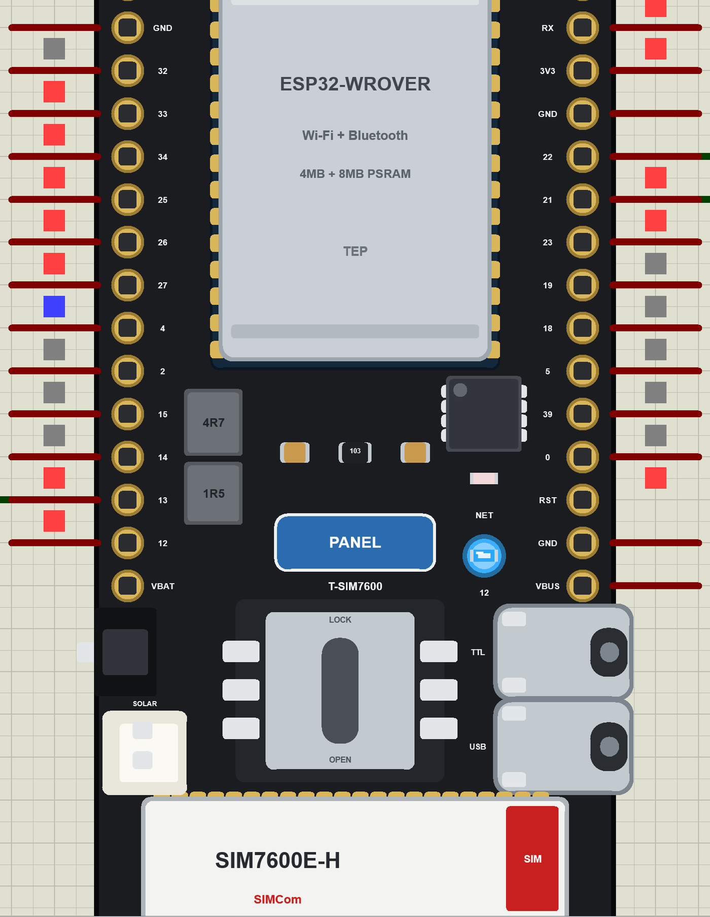
- The board as it looks: the black T-SIM7600 with the WROVER module, the TTL and USB Type-C ports, the slide switch, the solar socket, the nano SIM socket, the SIM7600, the PWR and RST buttons and the LTE and GNSS antenna sockets.
- Your sketch: a .hex for "T-SIM7600 (TEP Proteus)" with the board's GPIO numbers - analogRead 0 to 4095, analogWrite and ledc PWM, attachInterrupt, Serial, Serial1, Wire and SPI.
- A real modem on Serial1: AT, ATE, AT+CMGF, AT+CNMI, AT+CLIP, AT+CEREG?, AT+CSQ, AT+CPSI?, AT+CNSMOD?, AT+CMGS, ATH and ATA at 115200 baud, sent bit by bit on the pins, with PWRKEY on GPIO4 and FLIGHT on GPIO25.
- GPS in the modem: AT+CGPS, AT+CGPSINFO and AT+CGNSSINFO, in the formats of SIMCom's manual, with a position that moves.
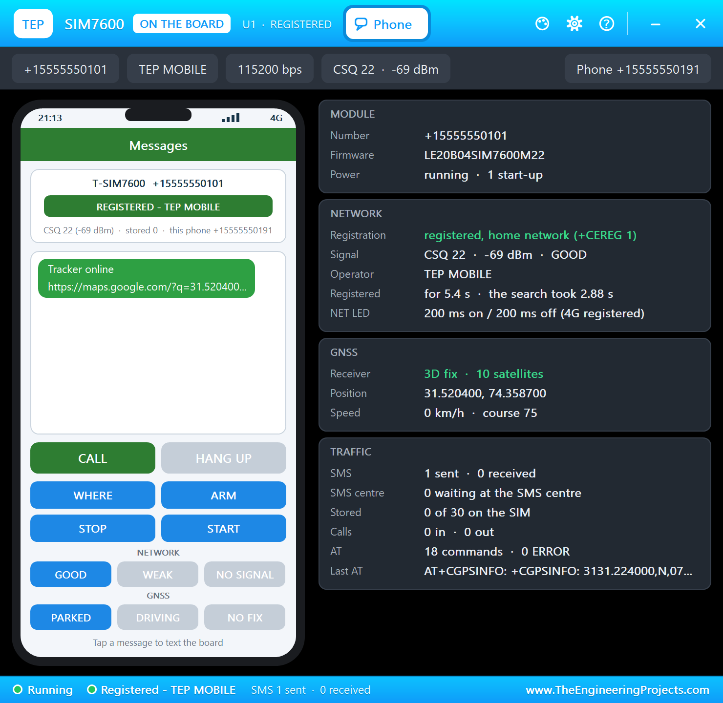
- A phone window: a click on the SIM7600 opens a phone that texts the board, shows its SMS, calls it, sets the signal, and parks, drives or hides the vehicle.
- The LEDs work: the blue LED follows GPIO12 and the red network LED stays on while the module searches, then flashes 200 ms on and 200 ms off on 4G.
- A complete package: about 4.1 MB with the board, the add-on, the MPU6050 and relay libraries and the demo, without the source code of the models.
The T-SIM7600 in Proteus
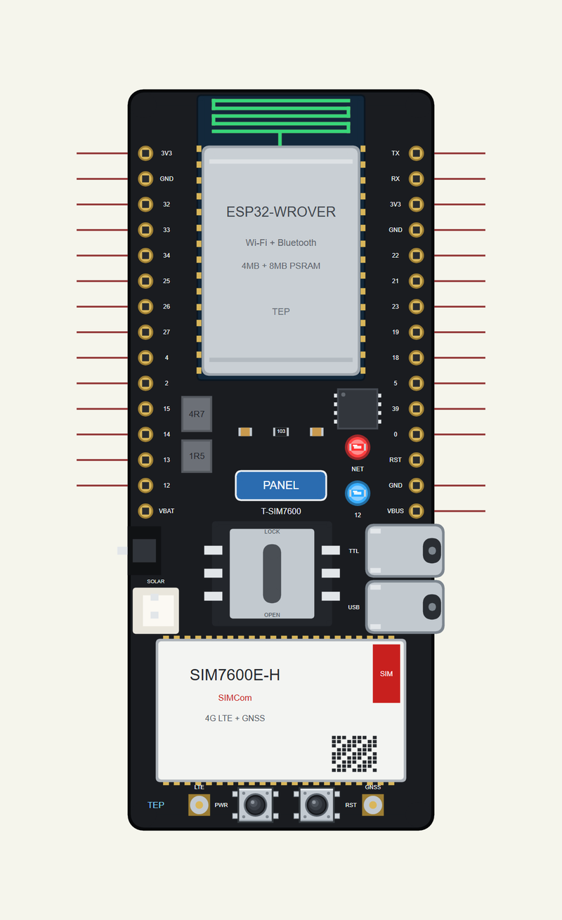
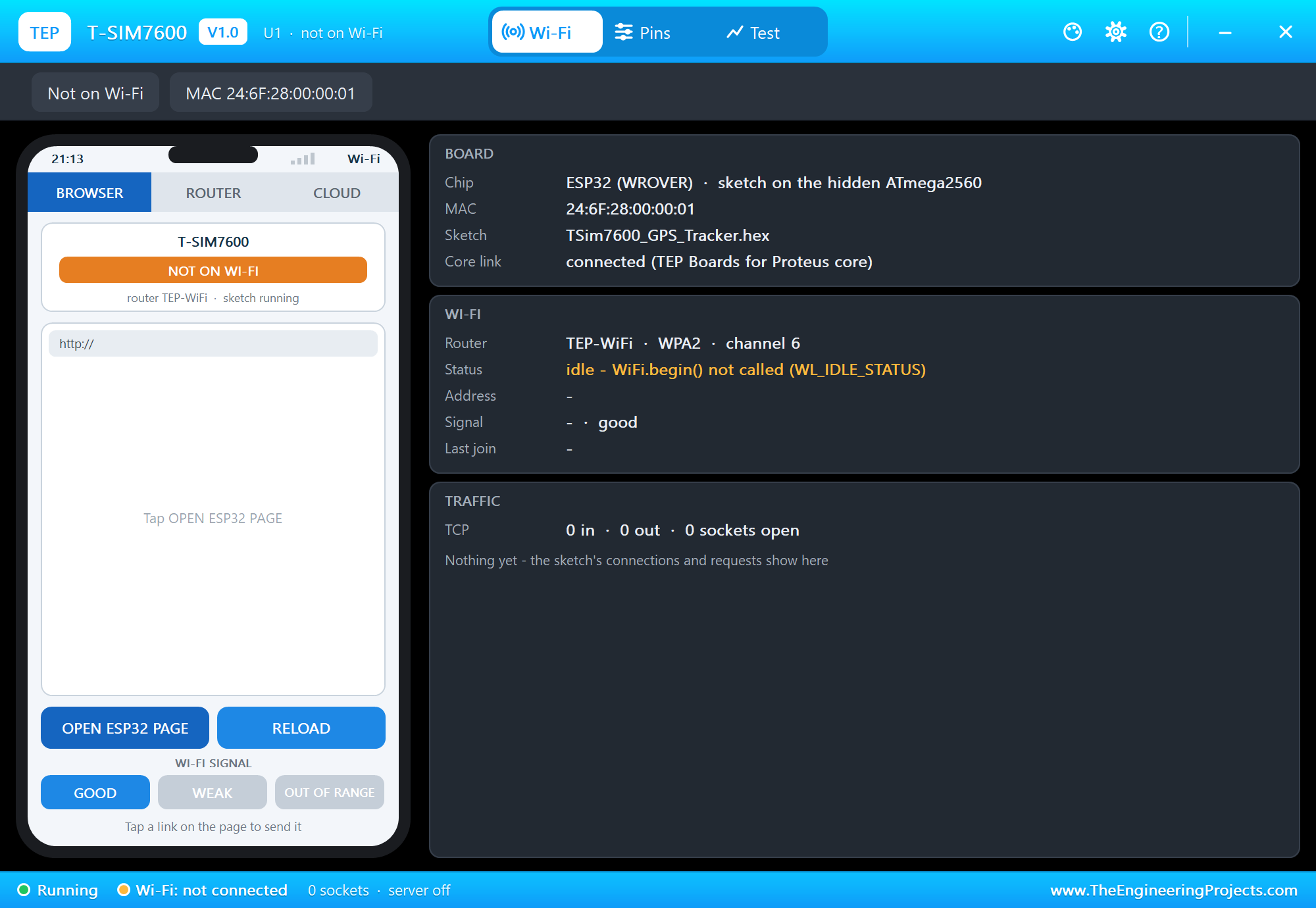
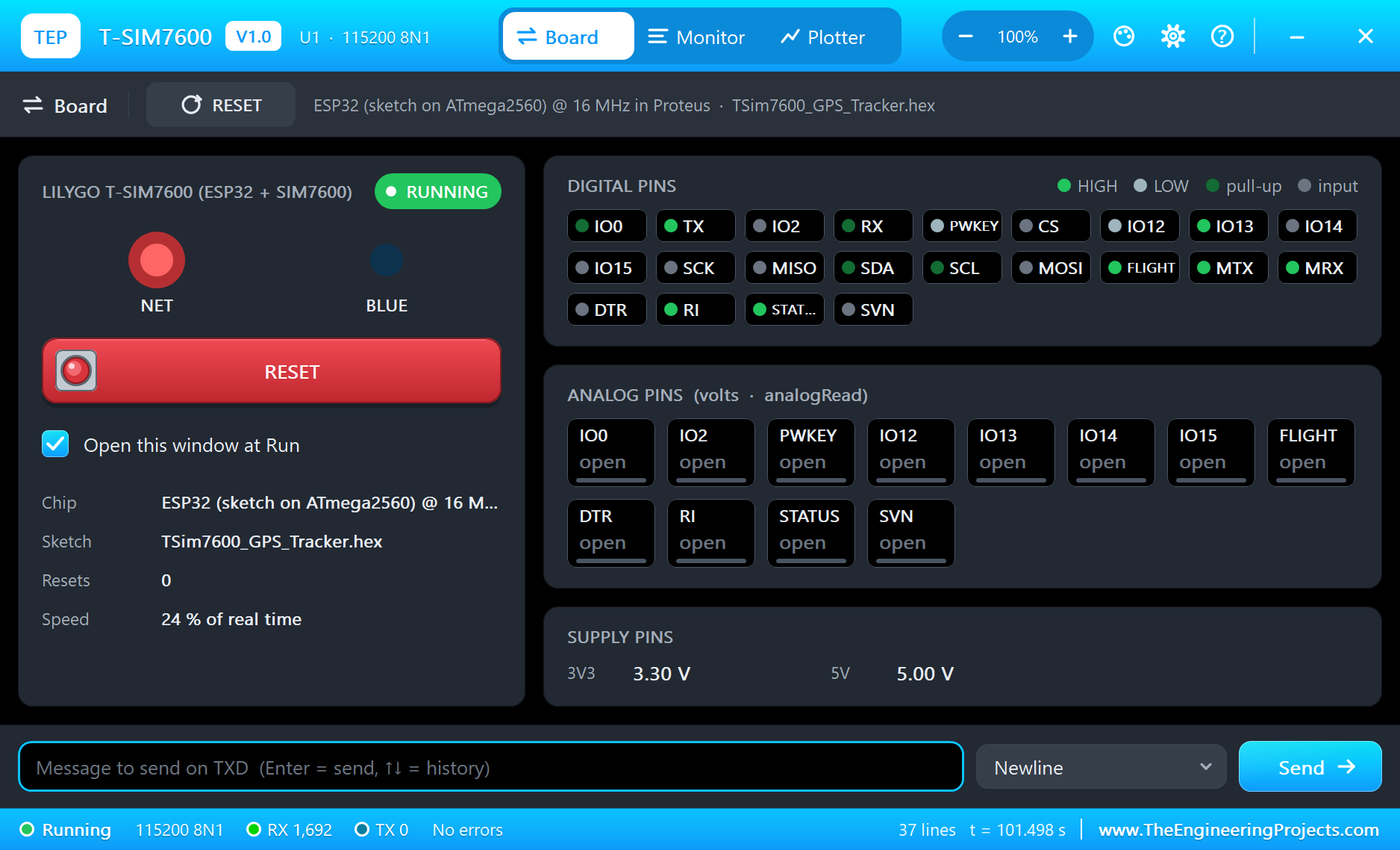
Search T-SIM7600 in Pick Devices; the device is in TEPTSIM7600.LIB (Microprocessor ICs, ESP32 Boards), with the prefix U. The board stands upright, with the antenna at the top. It has three windows: click the TTL port for the serial monitor, the PANEL pad for the board's panel, and the SIM7600 for the phone. We kept the real order of the 15 + 15 pads from LilyGO's board, and shortened it so that it stays a small part on an A4 sheet.
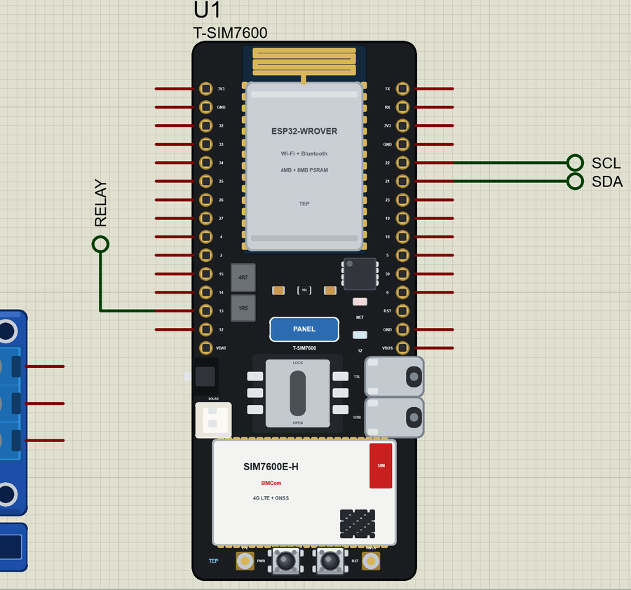
The Pins
| Pins | GPIO | What the library does with them |
|---|---|---|
| MODEM_TX, MODEM_RX | 27, 26 | Serial1, to the SIM7600, 115200 baud |
| MODEM_PWRKEY | 4 | a pulse starts the module |
| MODEM_FLIGHT | 25 | HIGH = normal, LOW = flight mode |
| MODEM_DTR, RI, STATUS | 32, 33, 34 | DTR, ring and the module's state |
| SDA / SCL | 21 / 22 | Wire |
| TX / RX | 1 / 3 | Serial, the board's monitor |
| 12 | LED_BUILTIN | the blue LED |
| 0, 2, 13, 14, 15 | - | GPIO, PWM, interrupt |
| 18, 19, 23, 5 | - | SPI |
As on the real board, GPIO4, 25, 26, 27, 32, 33 and 34 come out on the headers but belong to the modem, so keep them free. On a real board GPIO2, 13, 14 and 15 also go to the TF card. VBAT and RST are drawn only.
Download LilyGO T-SIM7600 Library for Proteus
Click the button below to download LilyGO-T-SIM7600-Library-for-Proteus-v1.0.zip (about 4.1 MB, without the source code of the models):
LilyGO T-SIM7600 Library for Proteus V1.0- README.txt: installation, the demo, the pins, the properties, troubleshooting and the limits.
- Proteus Library Files:
TEPTSIM7600.LIBand the demo's parts:TEPMPU6050.LIBandTEPRELAY.LIB. - Proteus Model Files:
TEPNET.DLL(the board and its modem),TEPMPU6050.DLLandTEPRELAY.DLL. - Arduino Code: the demo sketch and the TEP Boards for Proteus add-on 1.47.0.
- Proteus Simulation: the demo project, its HEX file and copies of the DLLs.
No Proteus yet? Read How to Download and Install Proteus 7 and 8. New to libraries? Follow How to Install a New Library in Proteus.
How to Install LilyGO T-SIM7600 Library for Proteus
- Close Proteus and extract the whole zip file, for example to your Desktop.
- Copy the files from Proteus Library Files into the LIBRARY folder of Proteus.
- Copy the DLLs from Proteus Model Files into the MODELS folder, replacing an older TEPNET.DLL.
- Delete
TEPTSIM7600.IDXfrom the LIBRARY folder if it is there. - For your own sketches, copy Arduino Code\TEP Boards for Proteus\hardware into your Arduino sketchbook (Documents\Arduino) and restart the Arduino IDE; the board is T-SIM7600 (TEP Proteus).
- Start Proteus, press P and search for T-SIM7600.
Demo: a 4G GPS Vehicle Tracker
Think of a motorbike parked outside a market, or a delivery van at the end of a long road. The owner wants three things from a small box tucked away inside: tell me where you are, warn me if someone touches you, and let me stop the engine. Our demo does all three, and a car owner with any old phone can use it, because everything travels by SMS.
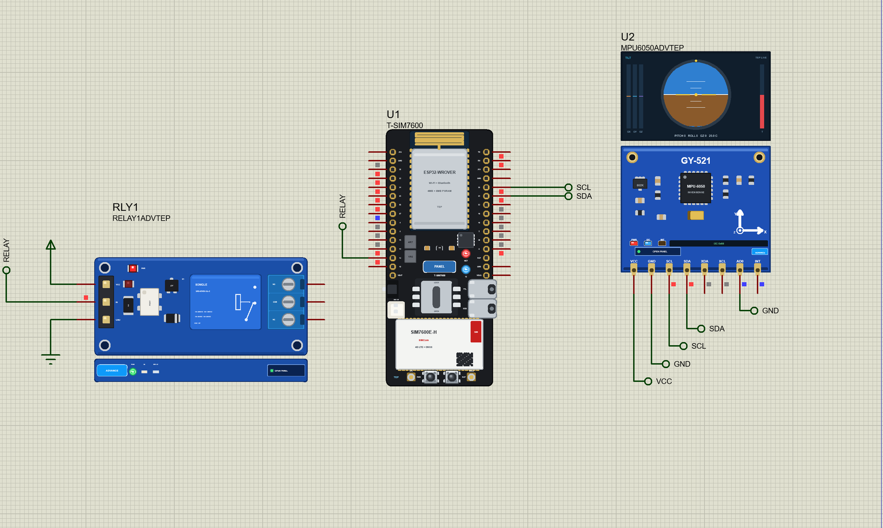
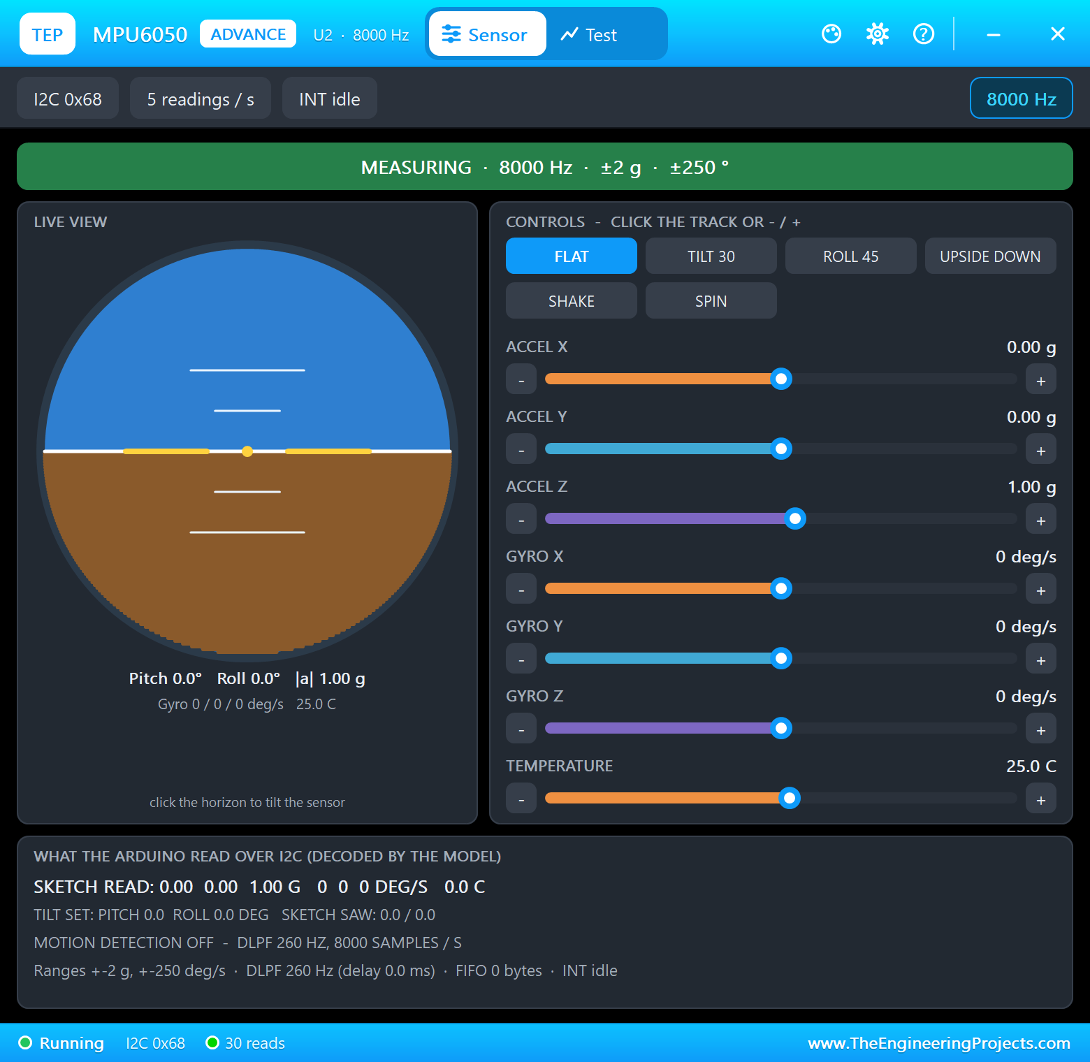
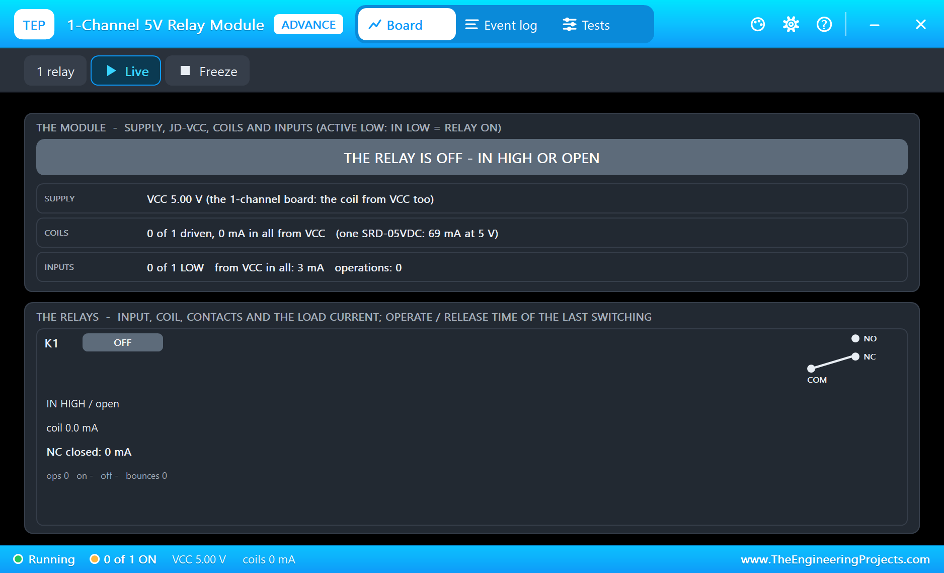
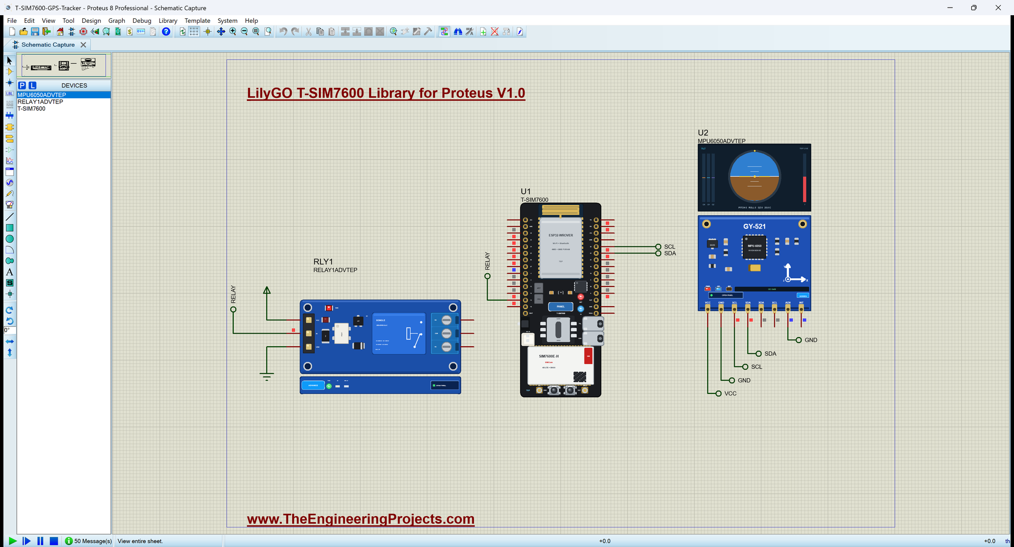
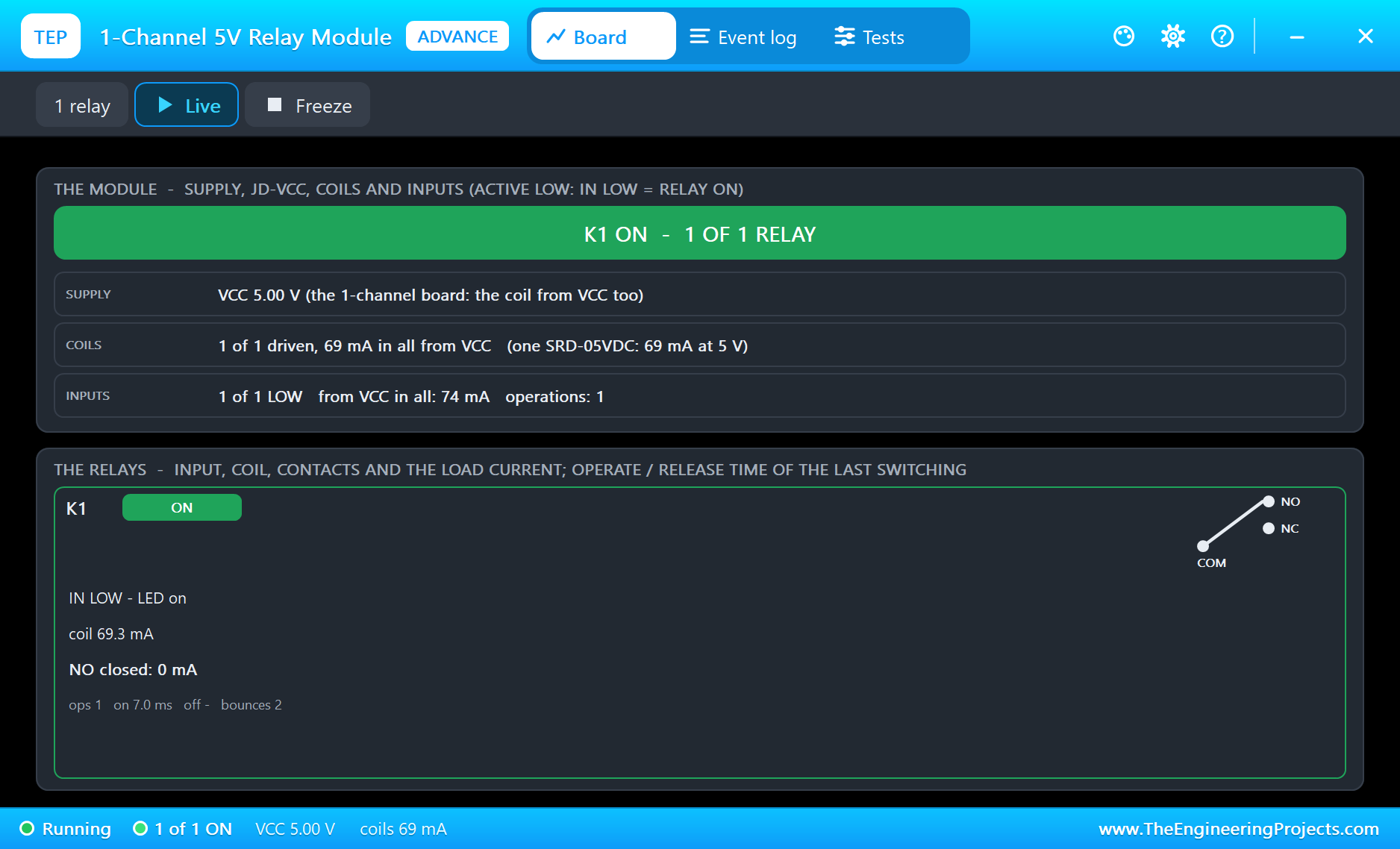
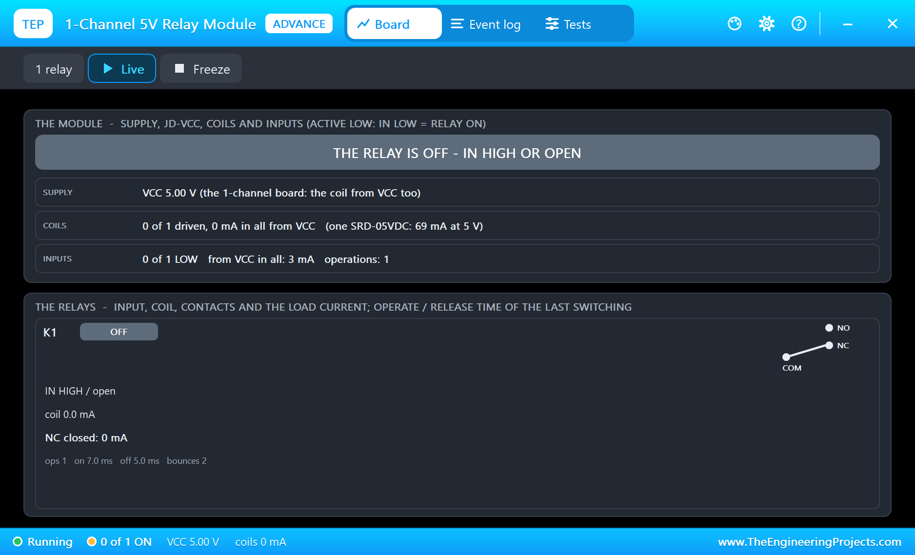
Open T-SIM7600-GPS-Tracker.pdsprj. U1 runs TSim7600_GPS_Tracker.hex. U2 is the sensor from our MPU6050 Library for Proteus and RLY1 the engine's relay from our Relay Module Library for Proteus - both in the Advance version, so they open their pop-up windows at Run. The monitor is the same window as our TEP Serial Monitor Advance for Proteus.
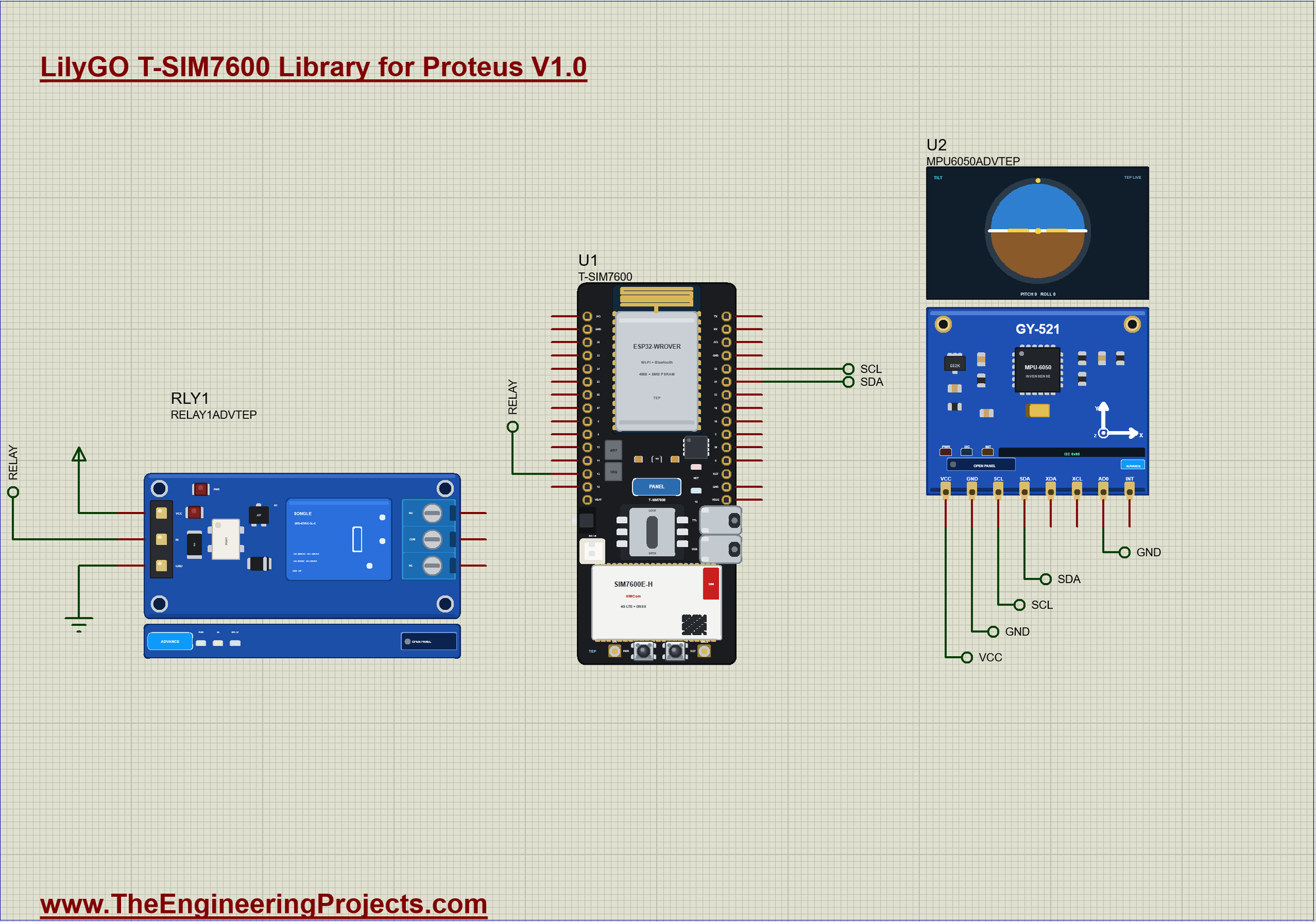
| Module pin | Net label | Board pin | What it does |
|---|---|---|---|
| MPU6050 SDA, SCL | SDA, SCL | 21, 22 | I2C, address 0x68 |
| MPU6050 VCC, GND | VCC, GND | - | the supply |
| MPU6050 AD0 | GND | - | selects 0x68 |
| Relay IN | RELAY | 13 | the engine, active LOW |
| Relay VCC, GND | VCC, GND | - | the supply |
Waking the Modem
The SIM7600 does not start by itself. A pulse on PWRKEY turns it on, just like holding the power button of a phone, and the sketch gives GPIO4 a 300 ms pulse. The FLIGHT pin must be HIGH, otherwise the module stays in flight mode with its radio off. Unlike the SIM800L, this module does not hunt for your baud rate: it is fixed at 115200, so the sketch keeps sending AT until an OK comes back. Then come the usual settings, and the last line starts the GPS:
void startModem() {
  pinMode(MODEM_PWRKEY, OUTPUT);
  digitalWrite(MODEM_PWRKEY, HIGH);                         // a 300 ms pulse starts the SIM7600
  delay(300);
  digitalWrite(MODEM_PWRKEY, LOW);
  pinMode(MODEM_FLIGHT, OUTPUT);
  digitalWrite(MODEM_FLIGHT, HIGH);                         // HIGH: not in flight mode
  SerialAT.begin(115200, SERIAL_8N1, MODEM_RX, MODEM_TX);
  Serial.println(F("Starting the SIM7600"));
  while (!sendAT("AT", 1000)) { }                           // it answers once it has started
  sendAT("ATE0", 500);
  sendAT("AT+CMGF=1", 500);                                 // SMS as text
  sendAT("AT+CNMI=2,2,0,0,0", 500);                         // a new SMS comes straight to the UART
  sendAT("AT+CLIP=1", 500);                                 // the caller's number with RING
  sendAT("AT+CGPS=1,1", 500);                               // the GPS on, standalone
}
Reading the GPS
AT+CGPSINFO returns one line. Until the receiver has a fix, it holds only commas. After that it gives the latitude, N or S, the longitude, E or W, the date, the time, the altitude, the speed in knots and the course. A small field() function picks one item out of that line by its position:
String field(const String &s, int n) {                      // the n-th field between commas
  int a = 0;
  while (n-- > 0) { a = s.indexOf(',', a) + 1; if (a == 0) return ""; }
  int b = s.indexOf(',', a);
  return b < 0 ? s.substring(a) : s.substring(a, b);
}
The position does not arrive in degrees. 3131.224000 means 31 degrees and 31.224 minutes, a format that goes back to the NMEA sentences of marine GPS. To get normal degrees, divide the minutes by 60. Google Maps wants them with six decimals, and here is a trap: a float holds only about seven digits, so 74.358700 would lose its last places and the point on the map would jump around. The sketch keeps each position in a long, in millionths of a degree, and never lets a float touch it:
long toDegrees6(const String &s) {                          // ddmm.mmmmmm or dddmm.mmmmmm to degrees x 1,000,000
  int dot = s.indexOf('.');
  long deg = s.substring(0, dot - 2).toInt();
  long minutes6 = s.substring(dot - 2, dot).toInt() * 1000000L + s.substring(dot + 1, dot + 7).toInt();
  return deg * 1000000L + minutes6 / 60;
}
Feeling a Bump
An MPU6050 measures acceleration on three axes. A parked vehicle always reads the same numbers, because the only force on it is gravity. When someone leans on it or lifts it, those numbers jump. The sketch reads the six acceleration bytes over I2C five times a second and adds up how far each axis has moved since the last reading. If that total passes 5000, which is about 0.3 g, and the tracker is armed, the alarm goes off:
void readMotion() {
  if (millis() < nextMotion) return;
  nextMotion = millis() + 200;
  Wire.beginTransmission(MPU);
  Wire.write(0x3B);                                         // ACCEL_XOUT_H
  Wire.endTransmission(false);
  Wire.requestFrom((int)MPU, 6);
  long x = readAxis(), y = readAxis(), z = readAxis();
  long jump = labs(x - lastX) + labs(y - lastY) + labs(z - lastZ);
  lastX = x; lastY = y; lastZ = z;
  if (armed && !alarmed && fix && jump > BUMP) alarm("bump");
}
Watching the Zone
The bump alarm misses a thief who drives away gently, so the GPS watches too. ARM stores the position, and each new reading is compared with it. For a short distance the Earth is flat enough: one millionth of a degree of latitude is about 0.111 m, and longitude shrinks by the cosine of the latitude. Our demo uses 100 m, because a real GPS wanders by several metres even when it stands still, and a smaller zone would give false alarms:
long movedMetres() {                                        // from where it was armed: a flat map is close enough for a short distance
  float north = (lat6 - homeLat) * 0.11132, east = (lon6 - homeLon) * 0.11132 * cos(lat6 / 1000000.0 * 0.0174533);
  return sqrt(north * north + east * east);
}
Answering the Owner
A new SMS arrives on the UART as a +CMT: header with the sender's number, then a line with the text. The sketch reads it as a command and always answers whoever wrote. A real product must check that number against a list, because anyone who knows the SIM number could otherwise stop your engine:
void command(const String &from, String text) {
  text.trim(); text.toUpperCase();
  Serial.print(F("SMS from ")); Serial.print(from); Serial.print(F(": ")); Serial.println(text);
  if (text == "WHERE") sendSms(from, status());
  else if (text == "ARM") {
    armed = true; alarmed = false; homeLat = lat6; homeLon = lon6;
    digitalWrite(LED_BUILTIN, HIGH);
    sendSms(from, "Armed at " + mapLink());
  }
  else if (text == "STOP") { digitalWrite(RELAY_PIN, LOW); sendSms(from, "Engine stopped"); }
  else if (text == "START") {
    armed = false;
    digitalWrite(RELAY_PIN, HIGH); digitalWrite(LED_BUILTIN, LOW);
    sendSms(from, "Engine free, alarm off");
  }
  else sendSms(from, "Commands: WHERE ARM STOP START");
}
The Free Missed Call
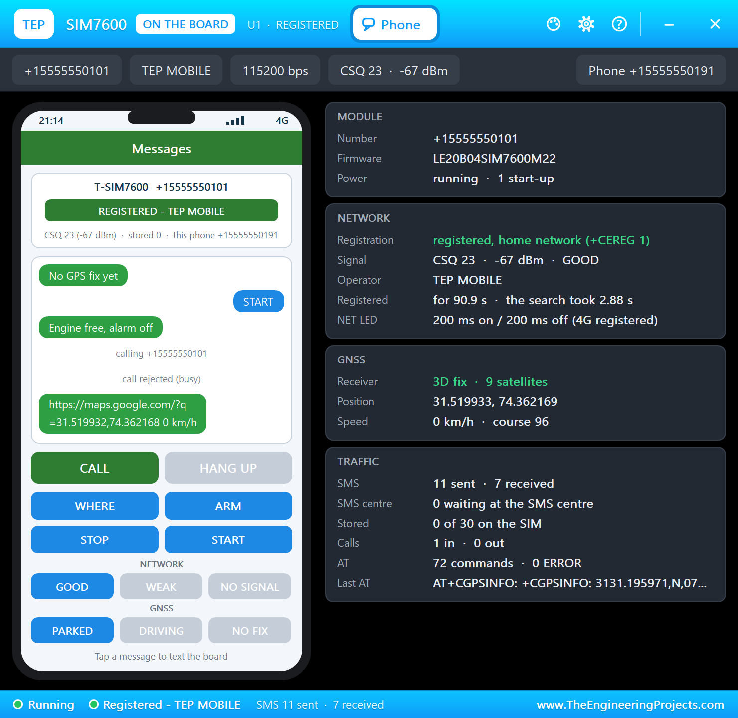
A call that is not answered costs nothing, so a missed call makes a free button. With AT+CLIP=1 the module sends the caller's number along with RING. The sketch hangs up with ATH and answers with the map link. It sits in the same function that sorts all the lines from the modem, the SMS and the GPS answers too:
void modemLine(const String &l) {
  if (smsNext) { smsNext = false; command(smsFrom, l); return; }
  if (l.startsWith("+CGPSINFO: ")) gpsLine(l.substring(11));
  else if (l.startsWith("+CMT:")) { smsFrom = between(l, '"'); smsNext = true; }
  else if (l.startsWith("+CLIP:")) caller = between(l, '"');
  else if (l == "RING" && caller.length()) {                // a missed call: hang up, answer by SMS
    Serial.print(F("Missed call from ")); Serial.println(caller);
    SerialAT.println(F("ATH"));
    delay(500);
    sendSms(caller, status());
    caller = "";
  }
}
Why the Sketch Never Waits for the GPS
Look at readGps(): it only sends the command and moves on. The answer comes back through readModem() like any other line. If the sketch stood still waiting for each reply, an SMS could arrive during that wait and be lost, and the MPU6050 would be read late. Keeping loop() short, with millis() for all the timing, lets four jobs share one processor.
Run the Demo
Press Run. The monitor opens and the sketch pulses PWRKEY. The red LED stays on while the module searches, then starts to flash when it is on 4G. The GPS needs a few more seconds, and the first SMS carries the first fix:
T-SIM7600 GPS Tracker - The Engineering Projects
Starting the SIM7600
On the 4G network
0.000000, 0.000000  0 km/h  not armed  SMS sent 0
GPS fix: 31.520400, 74.358700
SMS to +15555550191: Tracker online https://maps.google.com/?q=31.520400,74.358700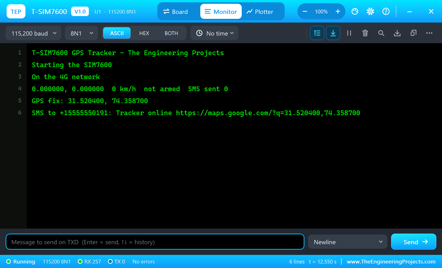
Where Is It?
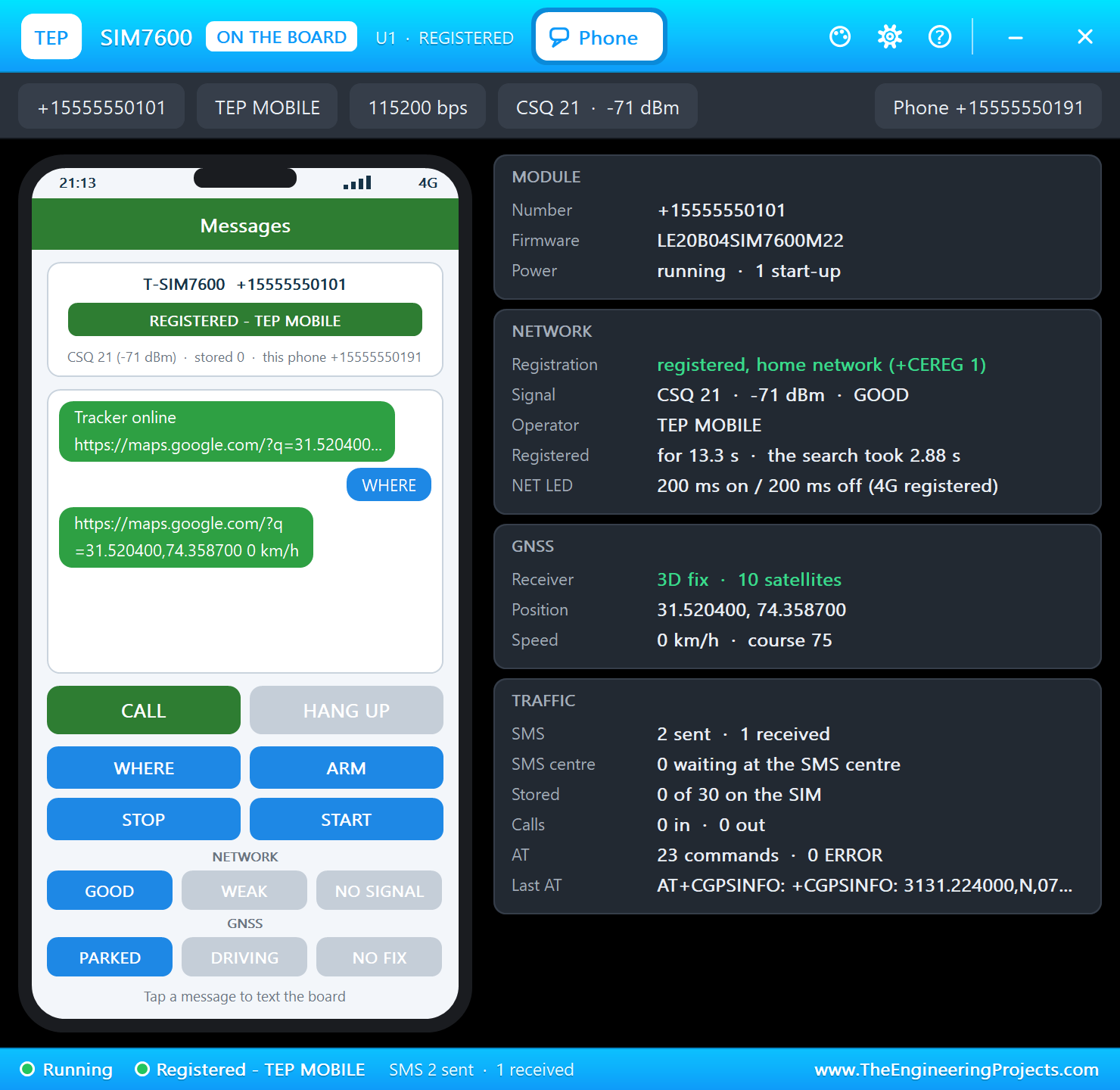
Tap WHERE on the phone. About two seconds later the map link comes back, with the speed behind it. On a real phone a tap on that link opens Google Maps with a pin on the vehicle:
Arm It
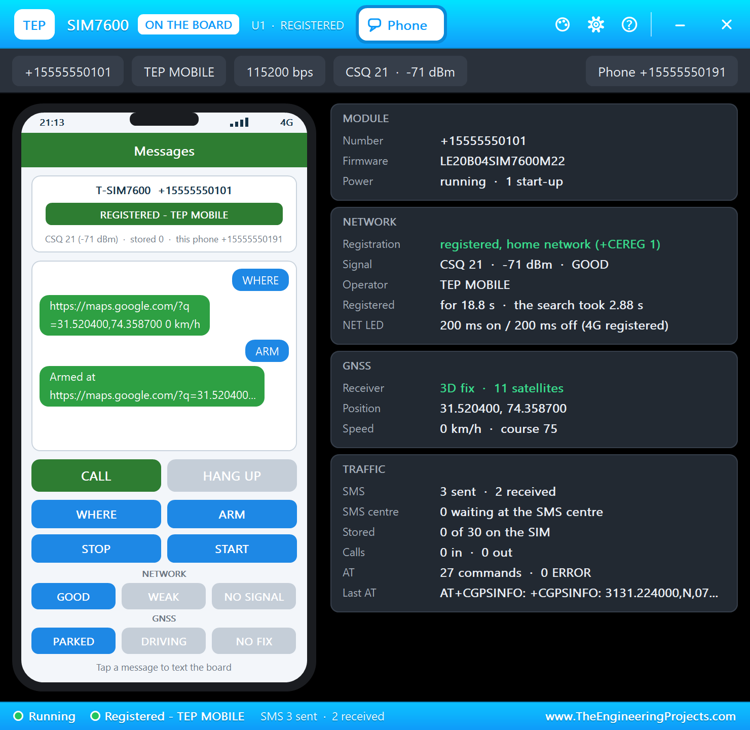
Tap ARM. The tracker stores this spot as home, and the blue LED lights to show that it is on guard:
A Bump
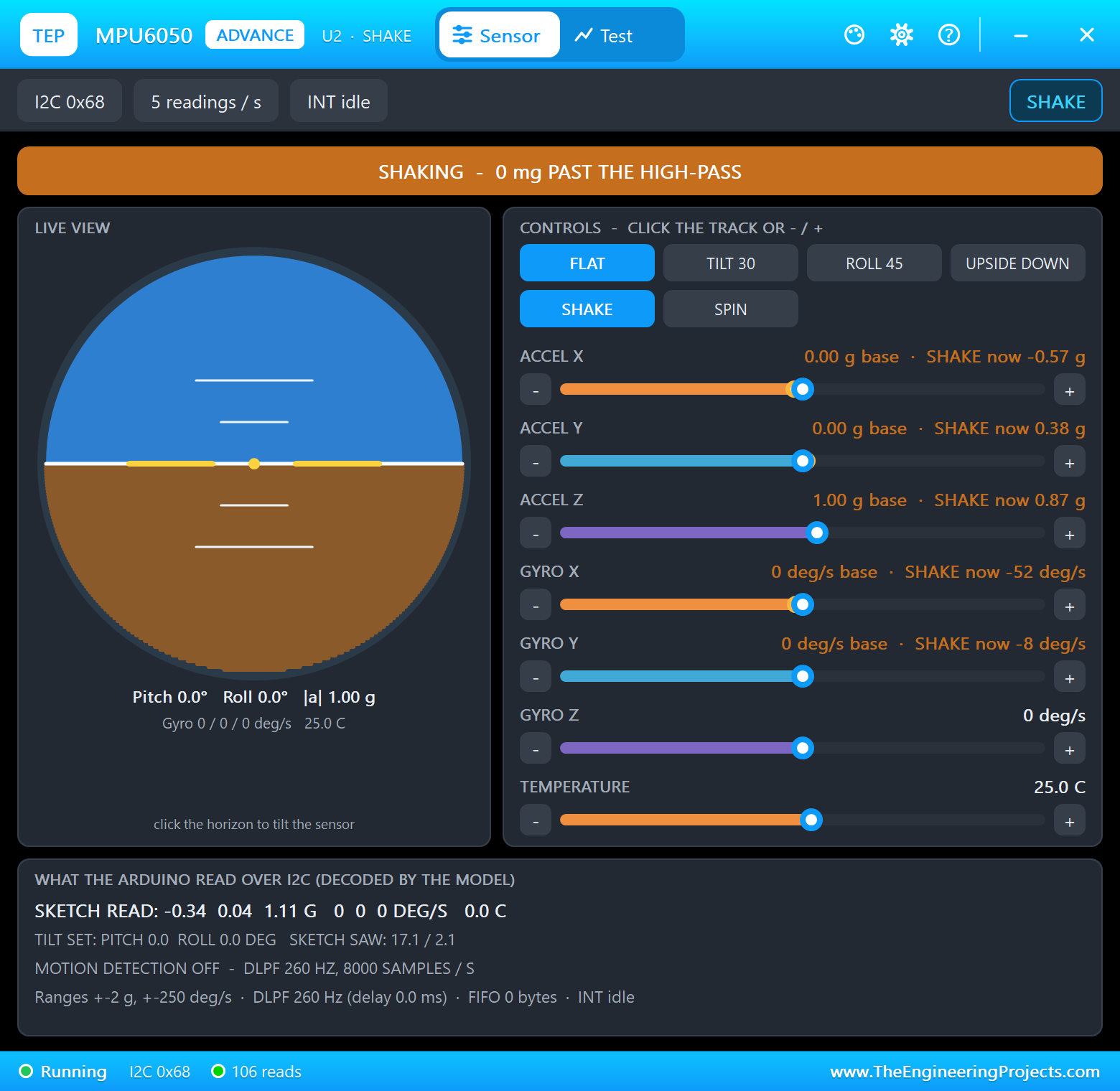
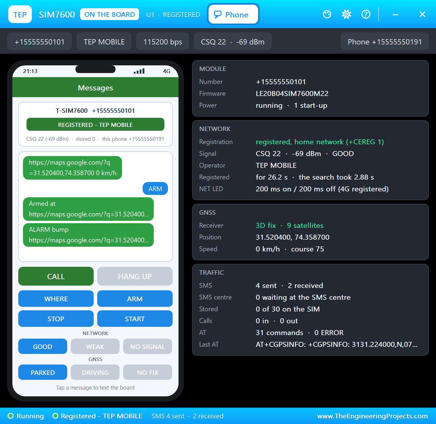
Click SHAKE on the MPU6050's window. The acceleration jumps, and the owner gets an alarm with a map link. It fires once, so a shaking vehicle does not empty your SMS credit. Click FLAT to calm it down:
A Thief Drives Away
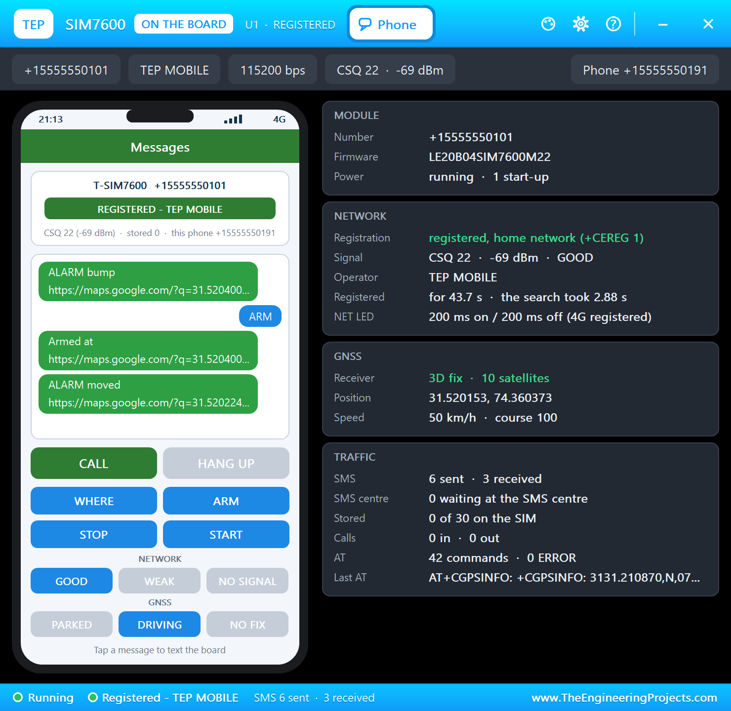
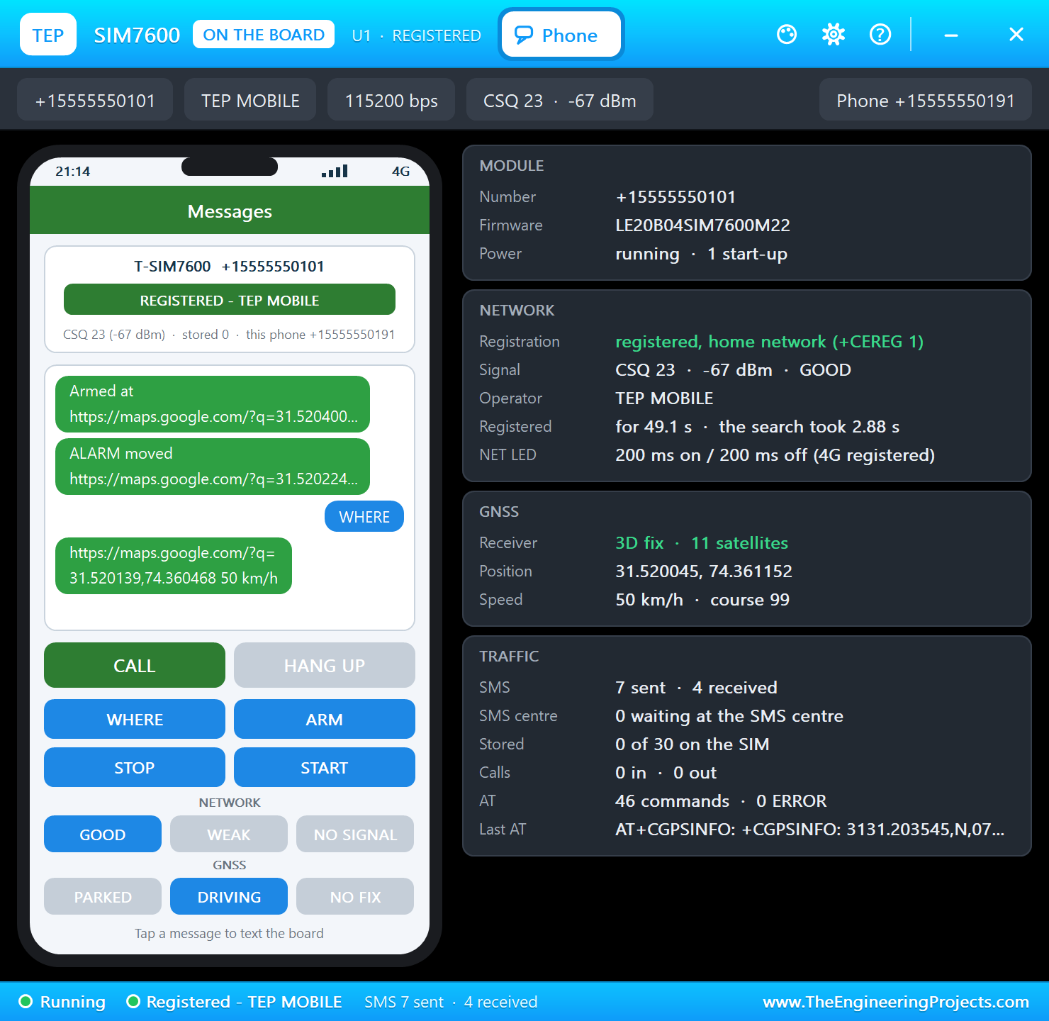
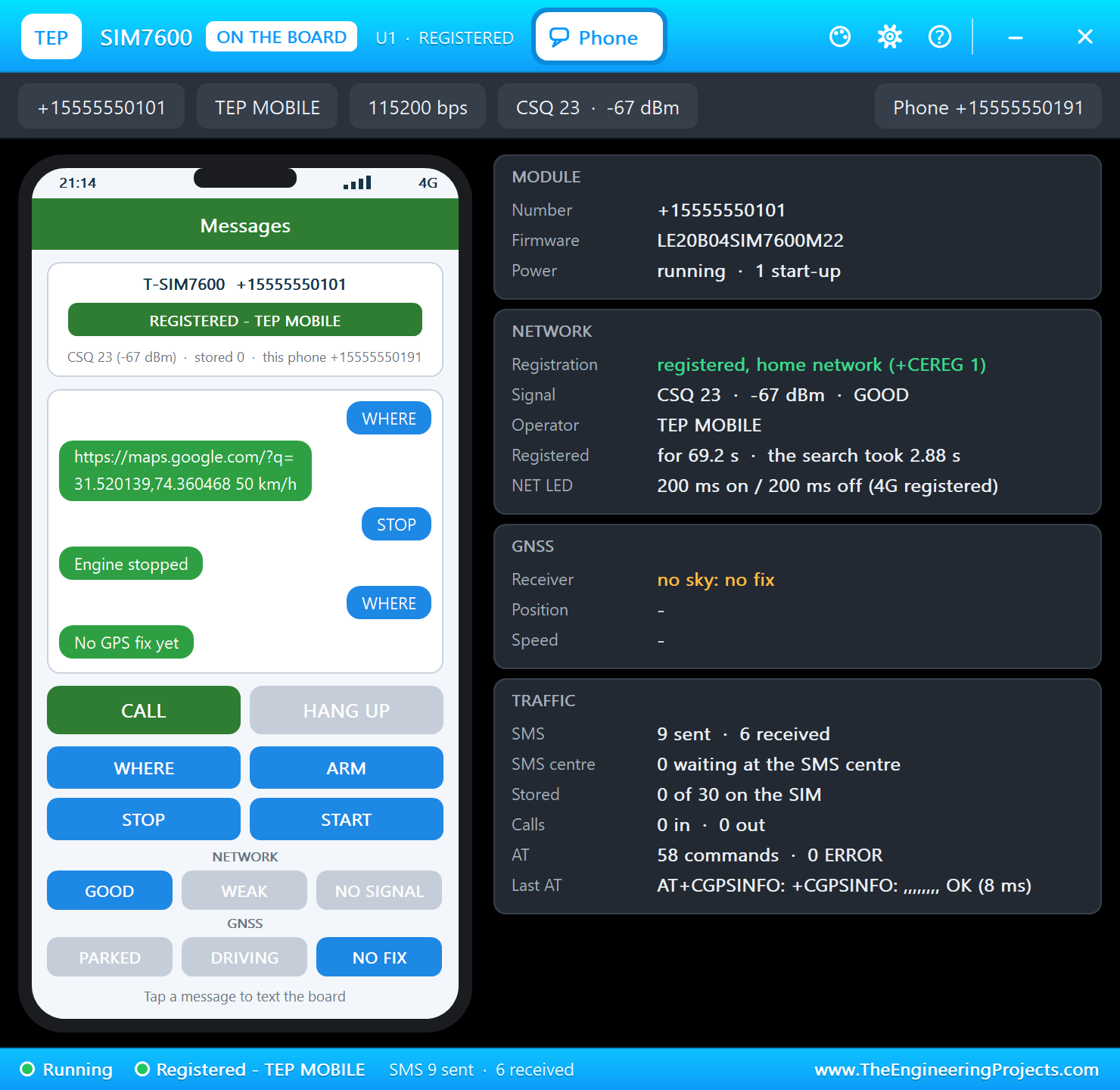
Tap ARM again, then DRIVING on the phone. The vehicle sets off at 50 km/h on a gentle curve. A few seconds later it is more than 100 m from home, and the second alarm goes out:
Stop the Engine
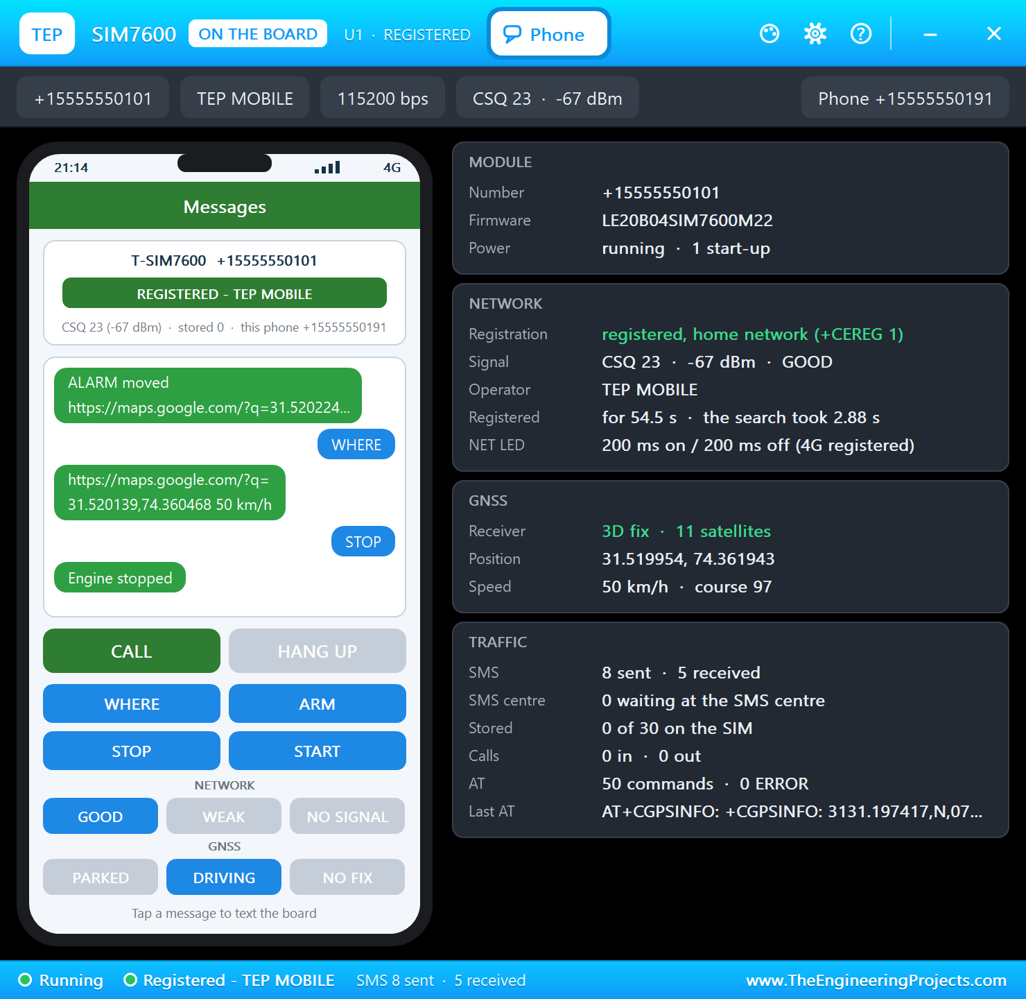
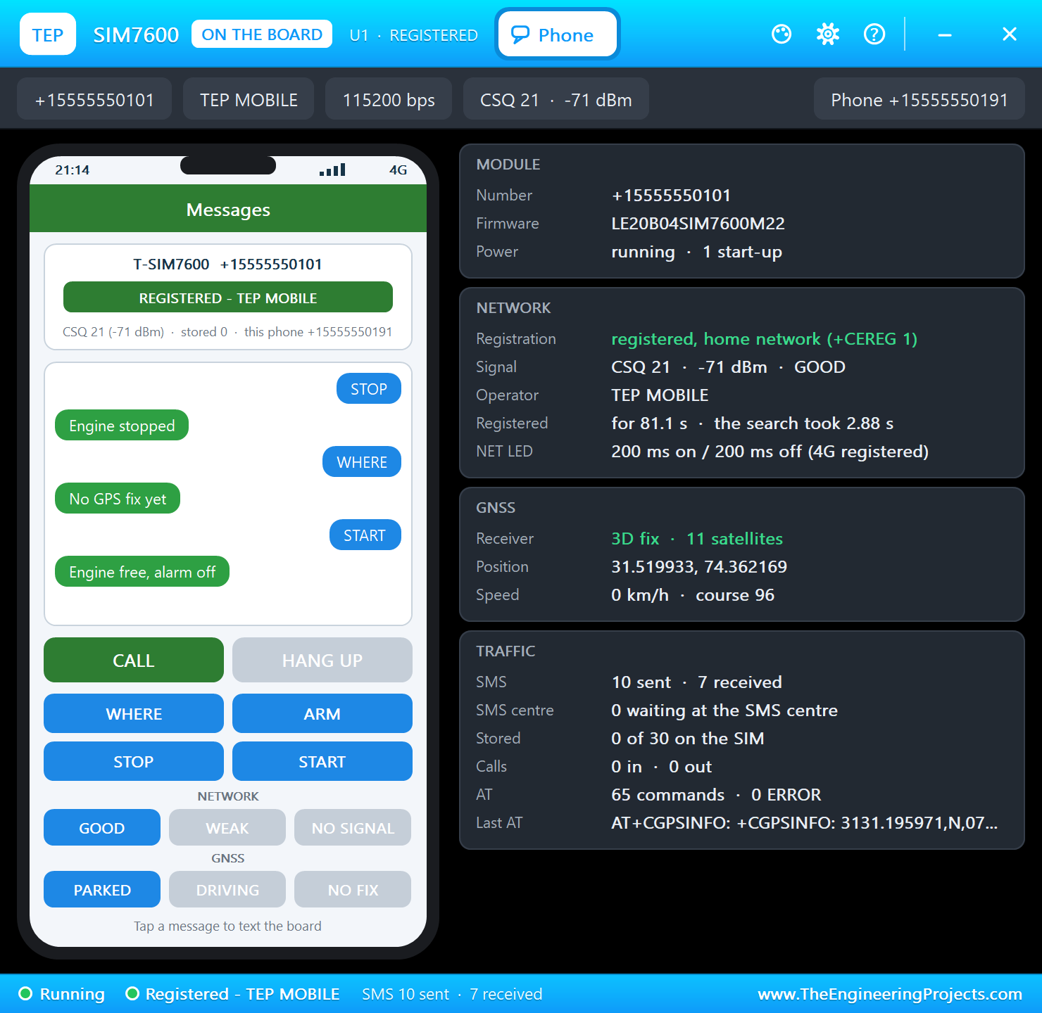
Tap STOP. The relay pulls in, and the answer comes back. START frees the engine and disarms the tracker:
Into a Tunnel
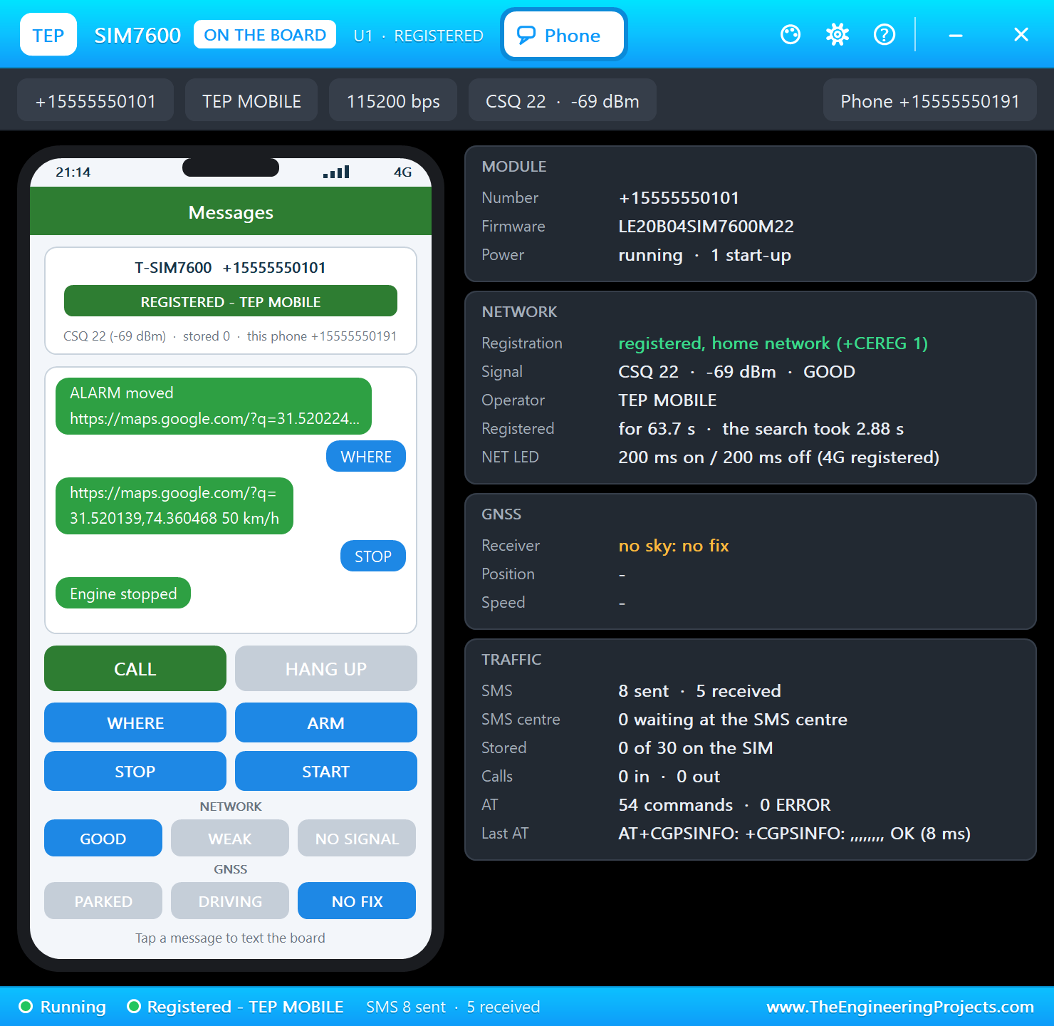
Tap NO FIX. The GPS loses the sky, AT+CGPSINFO goes back to commas, and the monitor prints a line. WHERE now answers honestly, and a tap on PARKED brings the fix back:
Free the Engine and Call
Tap START, then CALL. The board sees RING and the number, hangs up, and sends the map link:
The built-in serial monitor has followed everything:
SMS from +15555550191: WHERE
SMS to +15555550191: https://maps.google.com/?q=31.520400,74.358700 0 km/h
SMS from +15555550191: ARM
SMS to +15555550191: Armed at https://maps.google.com/?q=31.520400,74.358700
>> ALARM: bump
SMS to +15555550191: ALARM bump https://maps.google.com/?q=31.520400,74.358700
SMS from +15555550191: ARM
SMS to +15555550191: Armed at https://maps.google.com/?q=31.520400,74.358700
31.520267, 74.359603  50 km/h  armed  SMS sent 5
>> ALARM: moved
SMS to +15555550191: ALARM moved https://maps.google.com/?q=31.520224,74.359891
SMS from +15555550191: WHERE
SMS to +15555550191: https://maps.google.com/?q=31.520139,74.360468 50 km/h
SMS from +15555550191: STOP
SMS to +15555550191: Engine stopped
GPS: no fix
SMS from +15555550191: WHERE
SMS to +15555550191: No GPS fix yet
GPS fix: 31.519932, 74.362168
SMS from +15555550191: START
SMS to +15555550191: Engine free, alarm off
Missed call from +15555550191
SMS to +15555550191: https://maps.google.com/?q=31.519932,74.362168 0 km/h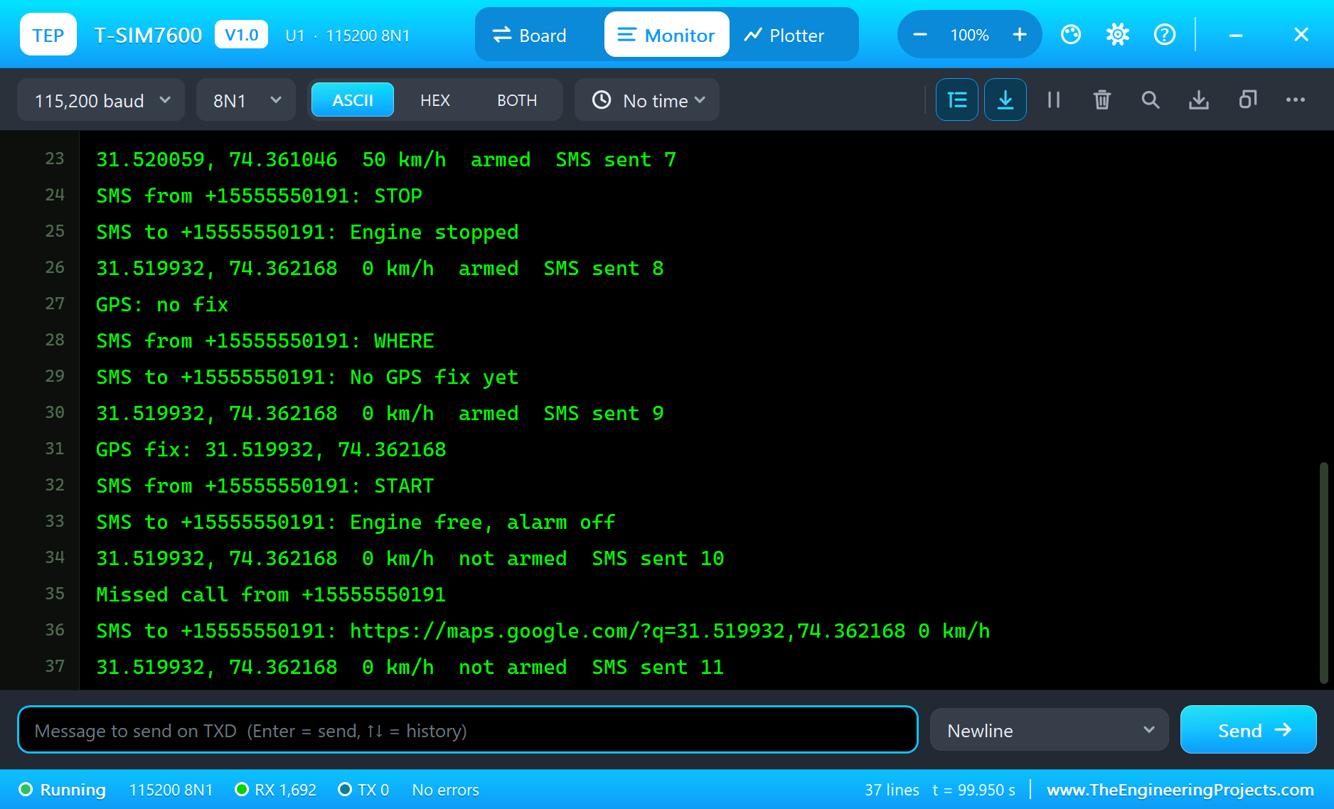
Try It Yourself
- Set
GPSLATandGPSLONon the board to your own town and run the demo again. - Tap NO SIGNAL on the phone and watch the red LED stay on while the module searches.
- Send
AT+CPSI?from your sketch and print the network the module reports. - Change
ZONE_MandBUMPand rebuild the sketch.
Ideas to Extend the Tracker
- Accept commands only from a list of known numbers.
- Send an alarm when the speed passes a limit, for a young driver or a hired van.
- Save the owner's number and the armed state in Preferences, so that a power cut does not lose them.
- Add a second relay for a siren.
Your Own Sketches
Write the sketch in the Arduino IDE with the board T-SIM7600 (TEP Proteus), use Sketch > Export Compiled Binary and set the board's PROGRAM property to the .hex. For a real board select "ESP32 Wrover Module" in Espressif's "esp32" package, define the MODEM pins and upload. The sketch sends plain AT commands, so it needs no modem library.
Things to Know Before Using a Real T-SIM7600
- Antennas first: connect the LTE antenna to the MAIN socket and an active GPS antenna to the GPS socket before you power the board.
- The first fix is slow: the simulation gives one after 6 s. A real module needs an open sky and much longer, so do not test GPS indoors.
- Two USB ports: the port marked TTL is the ESP32's serial port, and the one marked USB goes to the modem.
- Keep the modem's pins free: LilyGO warns against wiring GPIO4, 25, 32 and 33 on the header.
- Power: a modem draws sharp peaks while it transmits, so use a good 18650 cell. LilyGO notes that the battery reading on GPIO35 is 0 while USB is connected.
- A longer pulse: LilyGO's newer examples use 500 ms on PWRKEY for this module, and they wait up to 15 s for it to start.
- The legal side: tell the driver about a tracker, and never fit one to a vehicle that is not yours.
Choosing a Relay for an Engine
The relay on the sheet stands for the engine's cut-off. In a real vehicle the safe place is the starter or fuel pump circuit, wired so that the engine cannot die at speed. Use a relay rated for automotive current, fuse the supply, and ask a vehicle electrician to do the fitting. A sudden stop on a busy road can be dangerous, so a real tracker should allow STOP only when the speed is low.
Properties of the T-SIM7600
| Property | What it does |
|---|---|
| PROGRAM | the sketch: a .hex from TEP Boards for Proteus (board "T-SIM7600") |
| SIMNUM, PHONENUM | the SIM card's number and the phone's number |
| OPERATOR, GSMCLOCK | the network's name and the module's clock (PC or a date) |
| GPSLAT, GPSLON | where the vehicle starts |
| WIFISSID, WIFIPASS | the router in range (TEP-WiFi, 12345678) |
| MONITOR, BAUD, AUTOOPEN | the built-in serial monitor: on, its baud rate (115200), open at Run |
Troubleshooting
- The phone says NO POWER: pulse GPIO4 HIGH for 100 ms or more.
- The module never answers: use 115200 baud and keep sending AT until it says OK.
- AT+CMGS fails: wait for AT+CEREG? to show ,1; the module needs a few seconds.
- AT+CGPSINFO gives only commas: send AT+CGPS=1,1 first and wait for the fix.
- No SMS reaches the sketch: AT+CMGF=1 and AT+CNMI=2,2,0,0,0 in setup().
- A number goes wrong above 32767: int is 16 bits in the simulation - use long.
Limitations of the Simulation
- Your sketch gets 8 KB of RAM in the simulation, and there are no FreeRTOS tasks and no second core.
- The modem does SMS in text mode, calls and GPS. LTE data is not modelled, so TinyGSM's data functions, MQTT and HTTP through the SIM7600 will not work.
- Audio, PDU-mode SMS, the TF card, the battery and solar inputs and Bluetooth are not modelled.
- T-SIM7600 is a name of LilyGO, SIM7600 of SIMCom and ESP32 of Espressif Systems; this library is not made or endorsed by them or by Labcenter.
- Tested in Proteus 8.5 in October 2026 (the demo as shipped, about 100 s of simulation). Proteus 7 is not supported.
So, that was all about the LilyGO T-SIM7600 Library for Proteus. I hope it helps you build and test your 4G and GPS projects before you buy a SIM card - the modem, the map link, the alarms and the engine cut in one simulation. If you have any questions, ask in the comments and I will help you out. Till the next tutorial, take care and have fun!