Hello friends, I hope you all are doing great. Today, I am going to share the new Potentiometer Library for Proteus. The potentiometer, or simply the pot, is the knob of electronics. It sets the volume of a radio, the brightness of a lamp, the speed of a fan and the contrast of an LCD. On an Arduino it is usually the very first analog input anyone wires up, because one turn of the knob shows straight away how analogRead works.
Potentiometer Library for Proteus
Latest version: V1.0 (November 2026, this tutorial)
Other component libraries: C945 Transistor · PC817 Optocoupler · Relay Module · Resistor · 5 mm LED · Designer Colour LED · Push Button · Active Buzzer · Electrolytic Capacitor · Ceramic Capacitor · Tantalum Capacitor · Film Capacitor · 1N4007 Diode · Zener Diode · Schottky Diode · Supercapacitor · Photodiode · RGB LED · Bridge Rectifier · Flashing LED · Bi-Colour LED · SMD LED · Slide Switch · Toggle Switch · Rocker Switch · Micro Limit Switch · Emergency Stop Switch · SMD Resistor · Power Resistor · Resistor Network · Trimmer Potentiometer · Slide Potentiometer · NTC Thermistor · DIP Switch · Fuse · Passive Buzzer · Mini Speaker · 7-Segment Display · LED Bar Graph · IR / UV LED · Small Transistors · TIP122 Darlington · N-MOSFET · P-MOSFET · PC817 Optocoupler · Filament Bulb · Power LED · Voltage Regulator · SCR and TRIAC · Inductor · Toroid Inductor · Crystal
Helping Tools
- Serial Monitor Advance: a serial terminal window for the UART of your board
- Serial Monitor Expert: the serial monitor with extra debugging tools
- LCD Library for Proteus V3.0: 16x2, 20x4 and I2C LCDs to show your readings
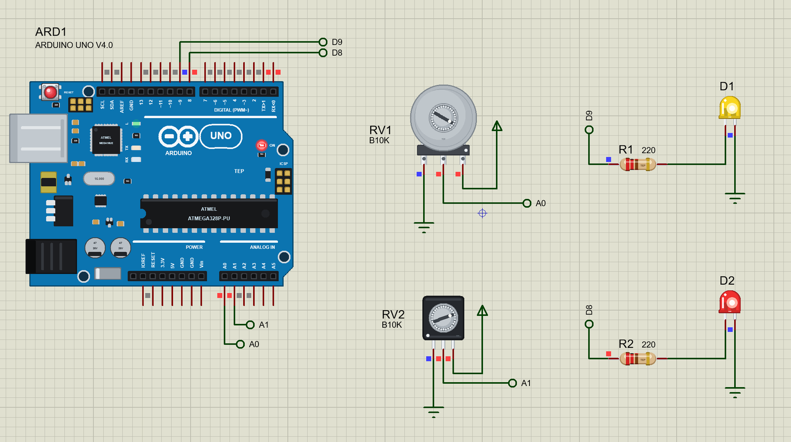
Our library has two rotary pots at true scale: a 16 mm panel pot with a metal cover and solder lugs, and a 9 mm pot with a black body and pins that fit a breadboard. Both are seen from the end of the shaft, with its knurled edge, its slot and a white index dot. At Run, you click the knob where you want the pointer, and it turns there. The value carries its taper, B10K or A10K, just like the print on a real one, and the pop-up shows the wiper voltage, both halves of the track and the taper curve. The demo is an LED dimmer with an alarm set point, on our Arduino UNO V4.0.
NOTICE: Our team has put a lot of effort into these small parts: the bodies, the animation and the pop-ups are all our own design, and you get them free. Your feedback is the fuel that keeps us going, so please tell us what you think in the comments below or in the Potentiometer board of our forum. And if our free libraries help you, you can buy us a coffee. So, let's get started with the Potentiometer Library for Proteus:
What is a Potentiometer?
A potentiometer is a resistor with a third terminal that slides along it. Inside, there is a curved track of resistive material, usually carbon, between two end pins. A small metal contact, the wiper, presses on the track and moves along it when you turn the shaft. The wiper comes out on the middle pin. So a pot is really two resistors in series, and turning the knob makes one of them bigger while the other gets smaller, while their sum stays the same.
The pins are numbered 1, 2 and 3. Pins 1 and 3 are the two ends of the track, and pin 2 is the wiper. Seen from the shaft, turning clockwise moves the wiper away from pin 1 and towards pin 3. A typical rotary pot turns through about 300 degrees between its two end stops; the remaining part of the circle is a dead zone that the knob never reaches.
| Feature | The real part | In the library |
|---|---|---|
| 16 mm pot | Alpha RV16 style, 0.2 W, 300 degrees | 672 thou across, true scale |
| 9 mm pot | Bourns PTV09 style, 0.05 W, 280 degrees | pins 2.5 mm apart, true scale |
| Shaft | 6 mm, knurled, slotted | the same, with a white index dot |
| Value | printed B10K, A50K and so on | typed the same way |
| Turning | by hand | a click on the knob at Run |
The Voltage Divider
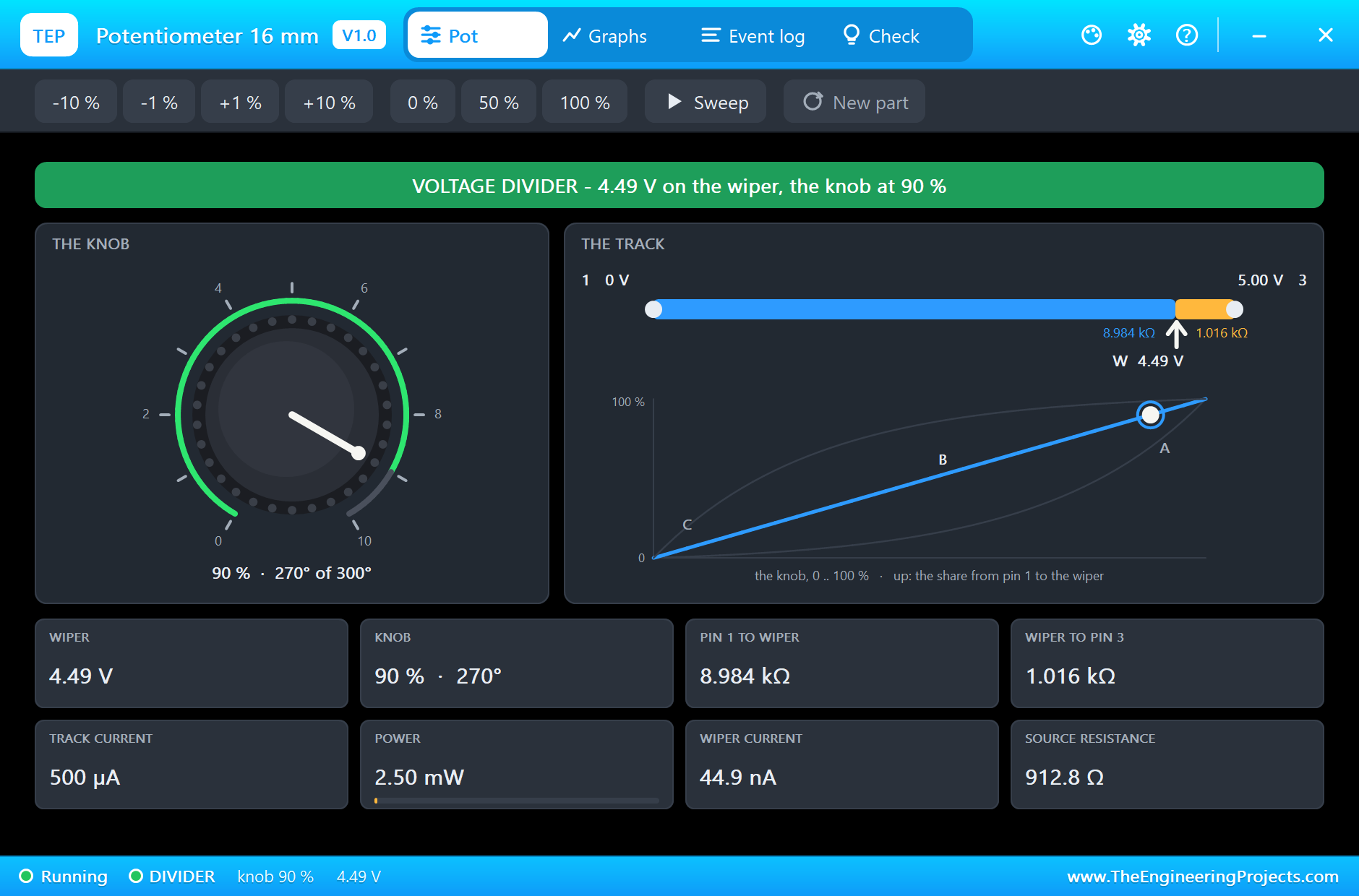
Connect pin 1 to ground and pin 3 to 5 V, and the wiper gives you any voltage between the two. The current flows through the whole track, and the wiper simply picks off a share of the voltage along the way. With the knob half way on a linear pot, the wiper sits at half the supply: 2.50 V. Turn it to 90 % and it reads 4.49 V. This is the most common way to use a pot, and it is the way our demo uses both of them.
Because almost no current leaves the wiper, the track behaves like a perfect divider. An Arduino analog input draws only a tiny current, so the voltage on the wiper follows the angle very closely. In our run, the wiper of RV1 never delivered more than 49.9 nA into the analog input. Put a heavy load on the wiper instead, and it drags the voltage down: the pop-up warns you when that happens.
The Taper
The taper describes how the resistance changes as you turn the knob. On a linear (B) pot, the share of the track between pin 1 and the wiper grows evenly with the angle. On an audio (A) pot, it grows slowly at first and quickly at the end, because the ear hears loudness on a logarithmic scale. A reverse audio (C) pot does the opposite. The letter is printed before the value, so B10K is a 10k linear pot.
| Knob | B (linear) | A (audio) | C (reverse audio) |
|---|---|---|---|
| 25 % | 25 % | about 4 % | about 60 % |
| 50 % | 50 % | about 15 % | about 85 % |
| 75 % | 75 % | about 40 % | about 96 % |
For an Arduino input, always pick a linear pot. An audio pot on an analog input reads low for most of its turn and then jumps up near the end, which feels broken even though it is working exactly as designed.
The Variable Resistor
Leave pin 3 unconnected, and the pot becomes a variable resistor, also called a rheostat: just the resistance between pin 1 and the wiper. This is handy, but there is a trap. Now the current flows through only part of the track, and that part may take only its share of the power rating. A 0.2 W pot turned to 10 % may take only about 20 mW. Near the end of its travel almost nothing of the track is left, and a current that seemed harmless burns it through. Our model checks this for you, and the pop-up shows how much of the allowed power each half is using.
Reading the Markings
Real pots print the taper and the value, often with the size in a part number. The common sizes are 9 mm, 16 mm and 24 mm across the body. The bigger the body, the more power it can handle and the smoother it feels, while the small ones fit on a breadboard or a crowded board. The values come in a short series: 1k, 2k, 5k, 10k, 20k, 50k, 100k, 500k and 1M are the ones you will meet most often, and 10k is by far the favourite for Arduino projects.
Choosing the Value
For a divider on an analog input, the value is a balance. A small pot, such as 1k, wastes 5 mA through its track all the time. A large one, such as 1M, wastes almost nothing, but its wiper then has a high source resistance, and the Arduino ADC needs a few microseconds to charge its sample capacitor through it. The ADC is happy with a source of up to 10 kohm. A 10k pot has at most 2.5k at its wiper, right in the middle of its travel, which is why B10K is the classic choice. The Check page of our pop-up works this out for you.
Features of the Potentiometer Library for Proteus
- The real look, at true scale: a 16 mm panel pot and a 9 mm breadboard pot, seen from the knurled shaft, with our small TEP signature.
- A knob you click: at Run, click the knob where the pointer should point, and it turns there. It stays there after Stop.
- Three tapers: type B10K, A10K or C10K, just like the print on a real pot.
- A divider or a variable resistor: the model knows which one you wired, and says so.
- True ratings: 0.2 W for the 16 mm pot and 0.05 W for the 9 mm one, derated for the part of the track in use, with heating and burn-out.
- A pop-up for every pot: the knob on its scale, the track with both halves, the taper curves, eight live values, graphs, an event log and a check page.
- Chips to turn it exactly: -10 %, -1 %, +1 %, +10 %, 0 %, 50 %, 100 % and a Sweep that turns the knob end to end.
- A complete package: about 1.9 MB with the library, our Arduino UNO V4.0, the demo's LEDs and resistors, and the demo, without the source code of the models.
The Potentiometers in Proteus
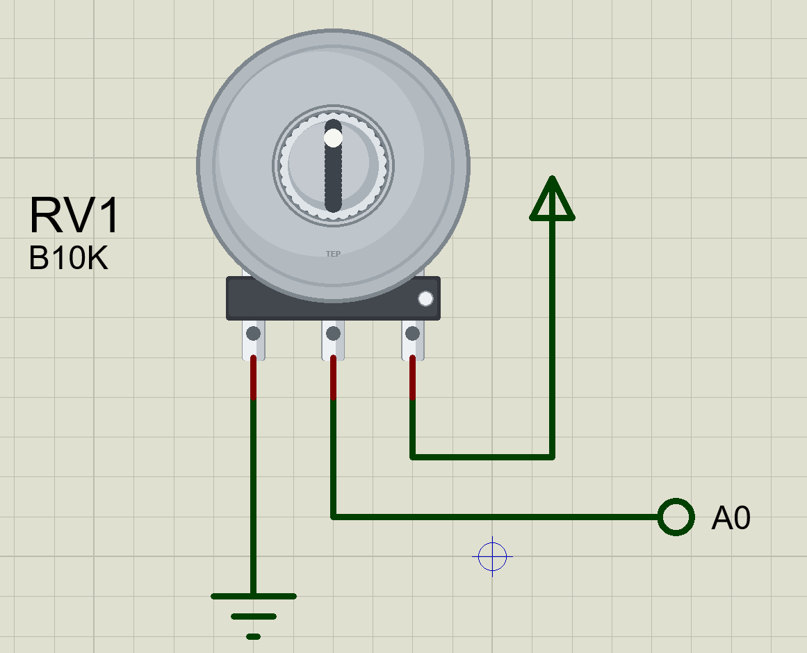
The devices are POTROTARY16TEP and POTROTARY9TEP in TEPPOT.LIB, under Resistors, Variable, with the prefix RV and the model TEPPOT.DLL. Search POTROTARY in Pick Devices. The pins are 1, W and 3, from left to right, exactly like a real pot seen from the shaft.
The Properties
| Property | What it does |
|---|---|
| Resistance and taper (VALUE) | B10K, A50K, C1M: the letter is the taper, B when you leave it out |
| Power rating, W | 0.2 for the 16 mm pot, 0.05 for the 9 mm pot: the whole track |
| Knob while stopped | 0 % to 100 % in steps of 5 %: where the knob starts |
Download Potentiometer Library for Proteus
Click the button below to download Potentiometer-Library-for-Proteus-v1.0.zip (about 1.9 MB, without the source code of the models):
Potentiometer Library for Proteus V1.0- README.txt: installation, the demo, the properties, troubleshooting and the limits.
- Proteus Library Files:
TEPPOT.LIB,TEPLED5MM.LIB,TEPRESISTOR.LIBand ourArduinoV4TEP.LIB. - Proteus Model Files:
TEPPOT.DLL,TEPLED5MM.DLL,TEPRESISTOR.DLLandTEPARDUINO.DLL. - Arduino Code: the demo sketch.
- Proteus Simulation: the demo project, its HEX file and copies of the DLLs.
No Proteus yet? Read How to Download and Install Proteus 7 and 8. New to libraries? Follow How to Install a New Library in Proteus.
How to Install Potentiometer Library for Proteus
- Close Proteus and extract the whole zip file, for example to your Desktop.
- Copy the files from Proteus Library Files into the LIBRARY folder of Proteus.
- Copy the files from Proteus Model Files into the MODELS folder.
- Delete
TEPPOT.IDXfrom the LIBRARY folder if it is there. - Start Proteus, press P and search for POTROTARY.
Demo: An LED Dimmer with a Set Point
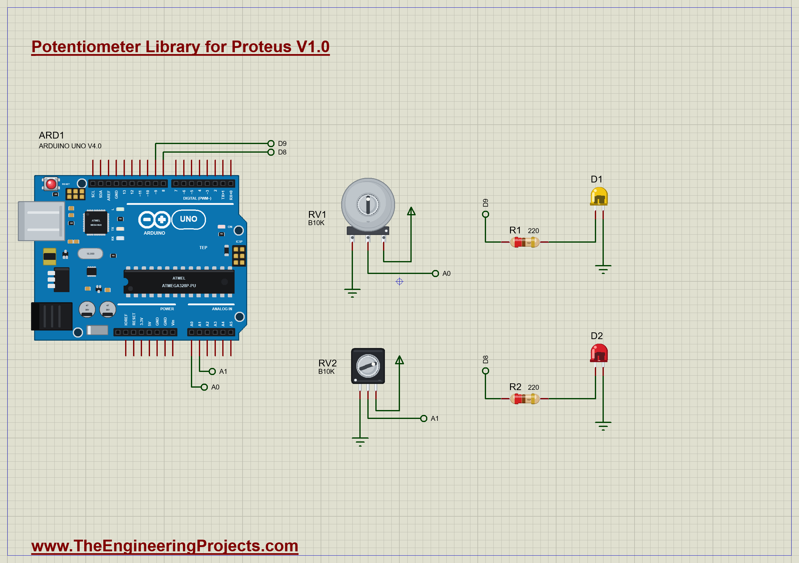
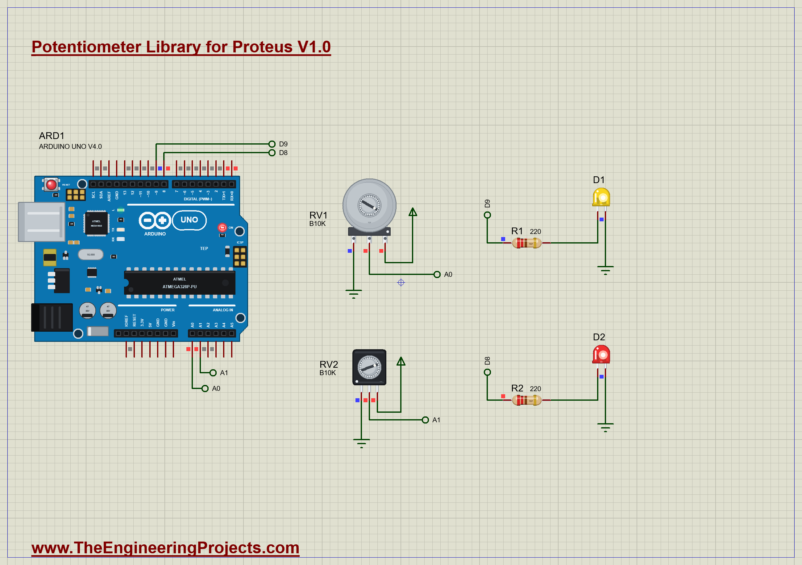
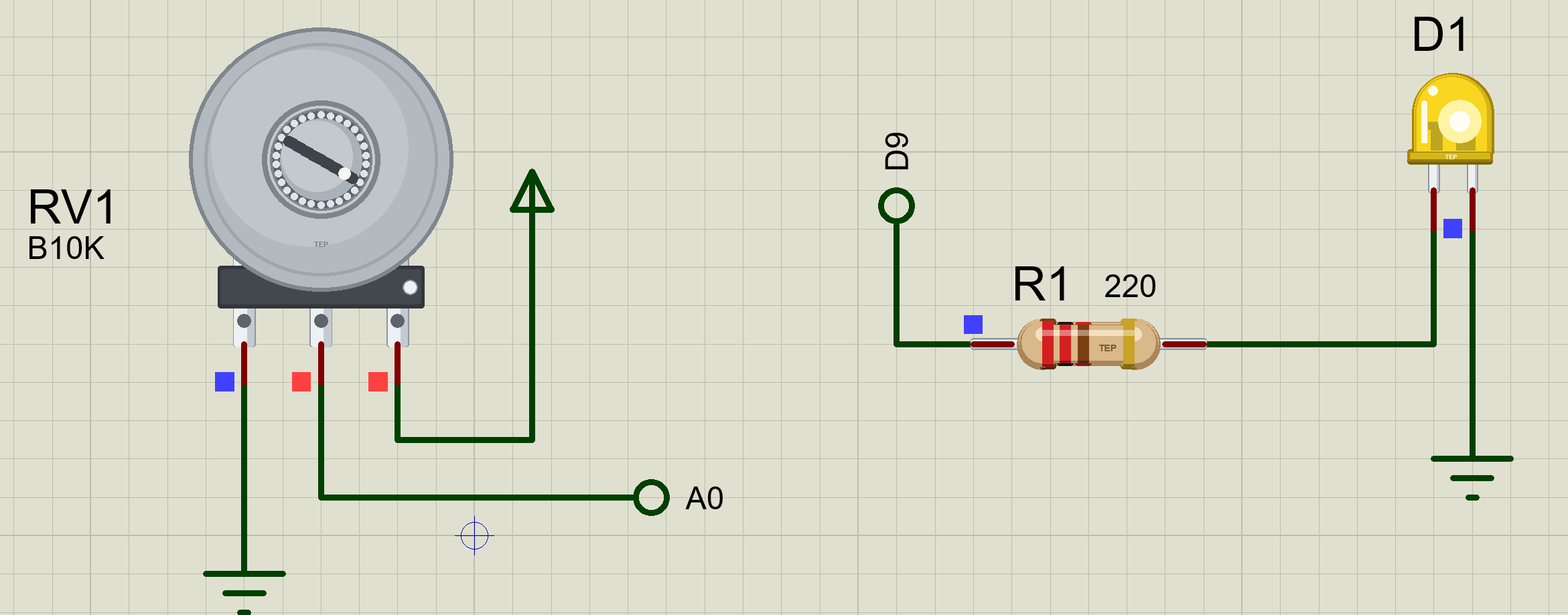
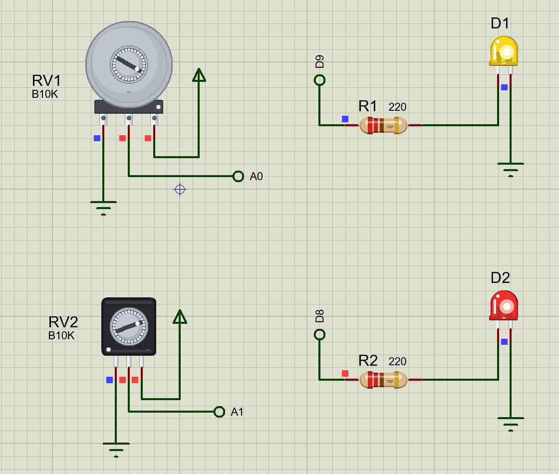
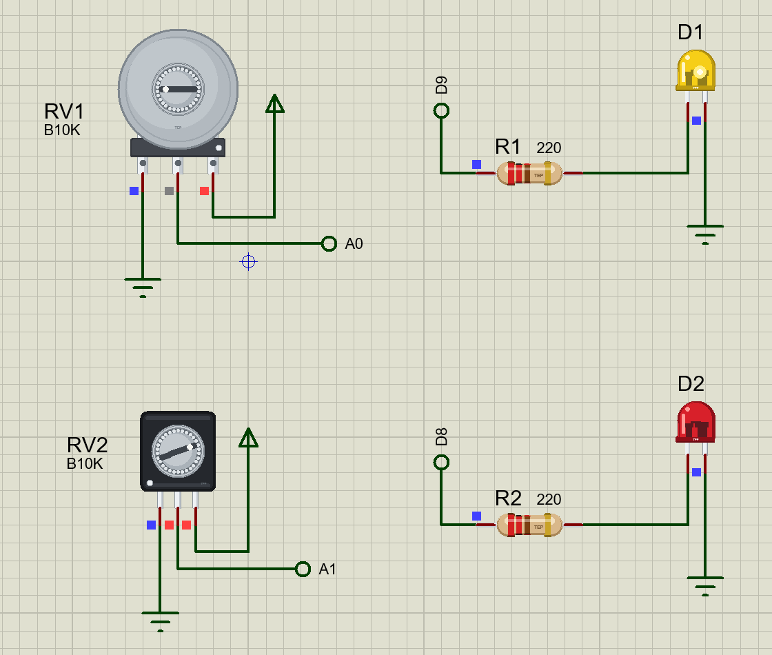
The demo uses both pots as voltage dividers, each with pin 1 on ground and pin 3 on 5 V. RV1, the 16 mm pot, is the level: its wiper goes to A0, and it sets the brightness of a yellow LED on D9. RV2, the 9 mm pot, is the set point: its wiper goes to A1. While the level is above the set point, a red alarm LED on D8 lights. It is the same pattern as a thermostat or a tank alarm, with the pots standing in for a sensor and a setting. Open Potentiometer-Dimmer-Setpoint-ArduinoUnoV4.pdsprj. It runs on our Arduino UNO Library for Proteus V4.0, with its built-in monitor, the same window as our TEP Serial Monitor Advance for Proteus. The LEDs are from our 5 mm LED Library for Proteus and the resistors from our Resistor Library for Proteus.
| Part | Connection | Job |
|---|---|---|
| RV1 (16 mm, B10K) | pin 1 GND, pin 3 +5V, wiper A0 | the level, starts at 50 % |
| RV2 (9 mm, B10K) | pin 1 GND, pin 3 +5V, wiper A1 | the set point, starts at 75 % |
| R1, D1 (yellow) | D9, 220 ohm, LED, GND | brightness follows RV1 |
| R2, D2 (red) | D8, 220 ohm, LED, GND | the alarm |
The Sketch
The loop reads both pots. The level becomes the PWM duty on D9: analogRead gives 0 to 1023, and analogWrite wants 0 to 255, so a division by four is all it takes:
  int level = analogRead(LEVEL_PIN);
  int setPoint = analogRead(SET_PIN);
  analogWrite(DIM_PIN, level / 4);                        // 0 .. 1023 becomes 0 .. 255
The alarm compares the two, with a little hysteresis: it turns on 10 counts above the set point and off 10 counts below it. Without that gap, a level resting right at the set point would make the LED flicker on every tiny wobble of the reading:
  if (!alarmOn && level > setPoint + HYST) alarmOn = true;
  if (alarmOn && level < setPoint - HYST) alarmOn = false;
  digitalWrite(ALARM_PIN, alarmOn ? HIGH : LOW);
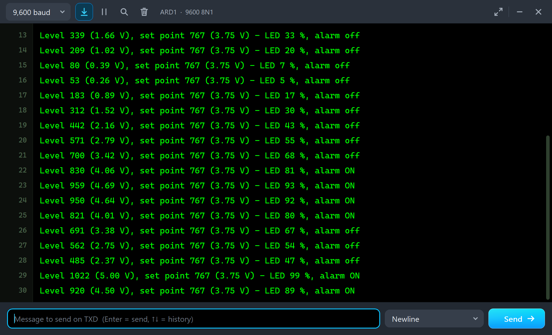
The sketch also prints a line on the monitor whenever a knob moves, at most twice a second, so a sweep does not flood the window.
Run the Demo
Press Run. RV1 starts at 50 %, so the yellow LED glows at half brightness, while the red LED stays dark:
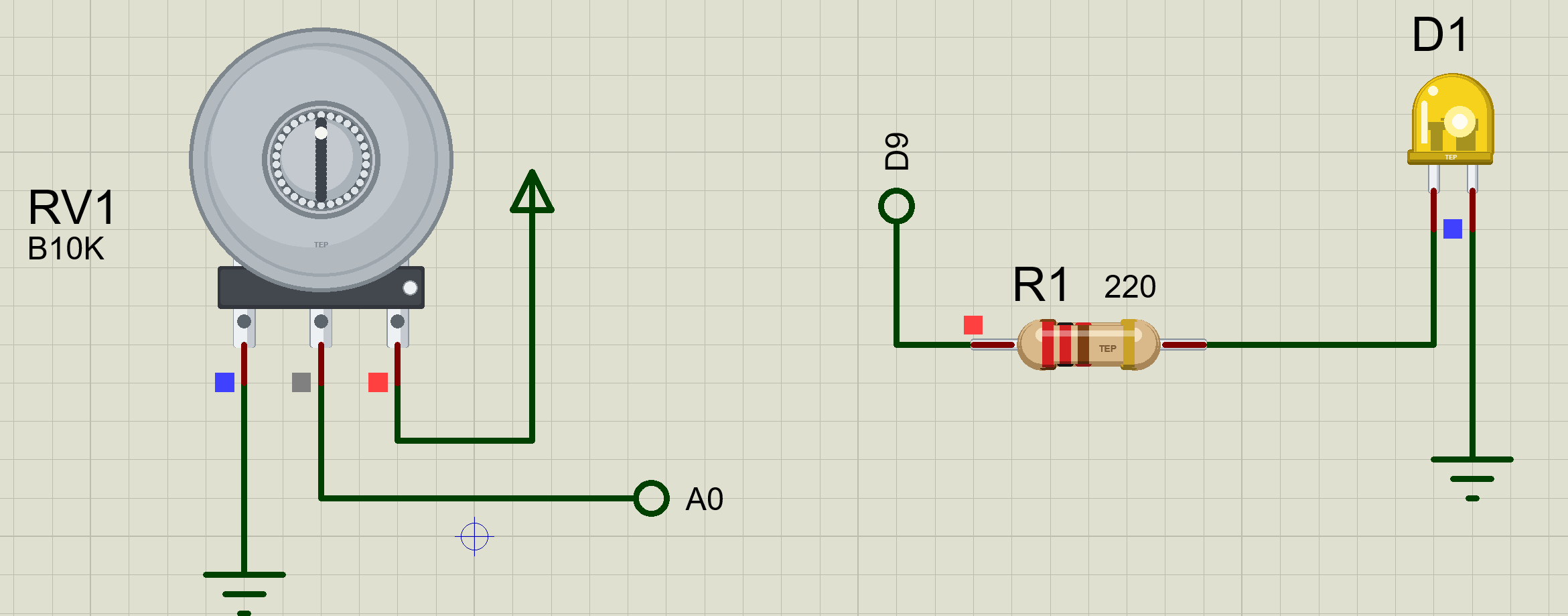
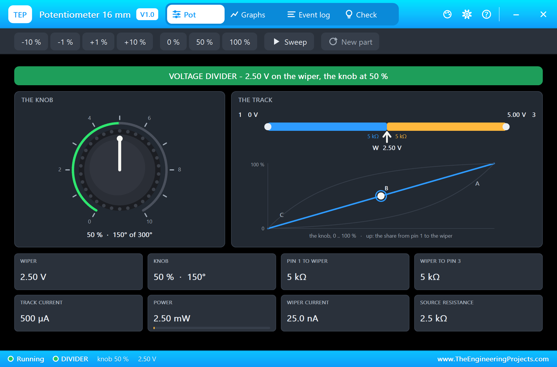
Click the small dot on RV1 to open its pop-up. The banner says how the pot is wired, a voltage divider, and the wiper reads 2.50 V. The track carries 500 µA, the full 5 V across 10k, and burns just 2.50 mW. The taper chart shows the straight B line with the knob's point on it:
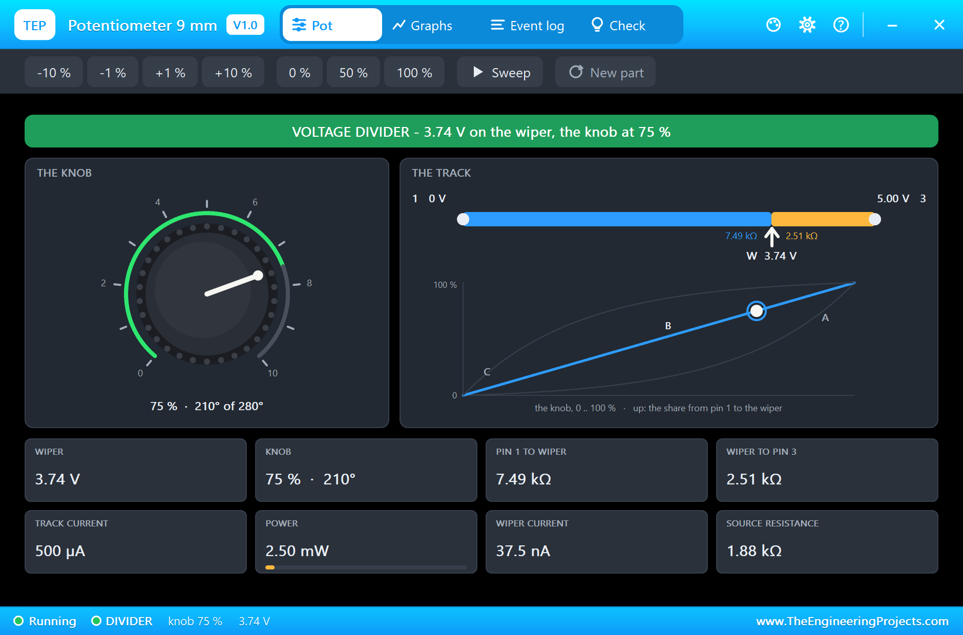
RV2's pop-up shows the set point. Its knob is at 75 %, so the wiper sits at 3.74 V, which the Arduino reads as 767:
Turning Up the Level
Now turn RV1 up. Click +10 % four times on its pop-up, or simply click its knob on the sheet towards four o'clock. As the level passes 818, above the set point plus the hysteresis, the red alarm LED lights. Here is the complete circuit, truly running, with the knob at 90 %:
RV1's pop-up now reads 4.49 V on the wiper, with 8.984 kohm between pin 1 and the wiper and 1.016 kohm on the other side. The source resistance at the wiper has fallen to 912.8 ohm, since the wiper is close to the 5 V end:
The monitor tells the same story, one line for each step of 10 %. The alarm turned on at the line where the level reached 818:
The Sweep, the Log and the Check Page
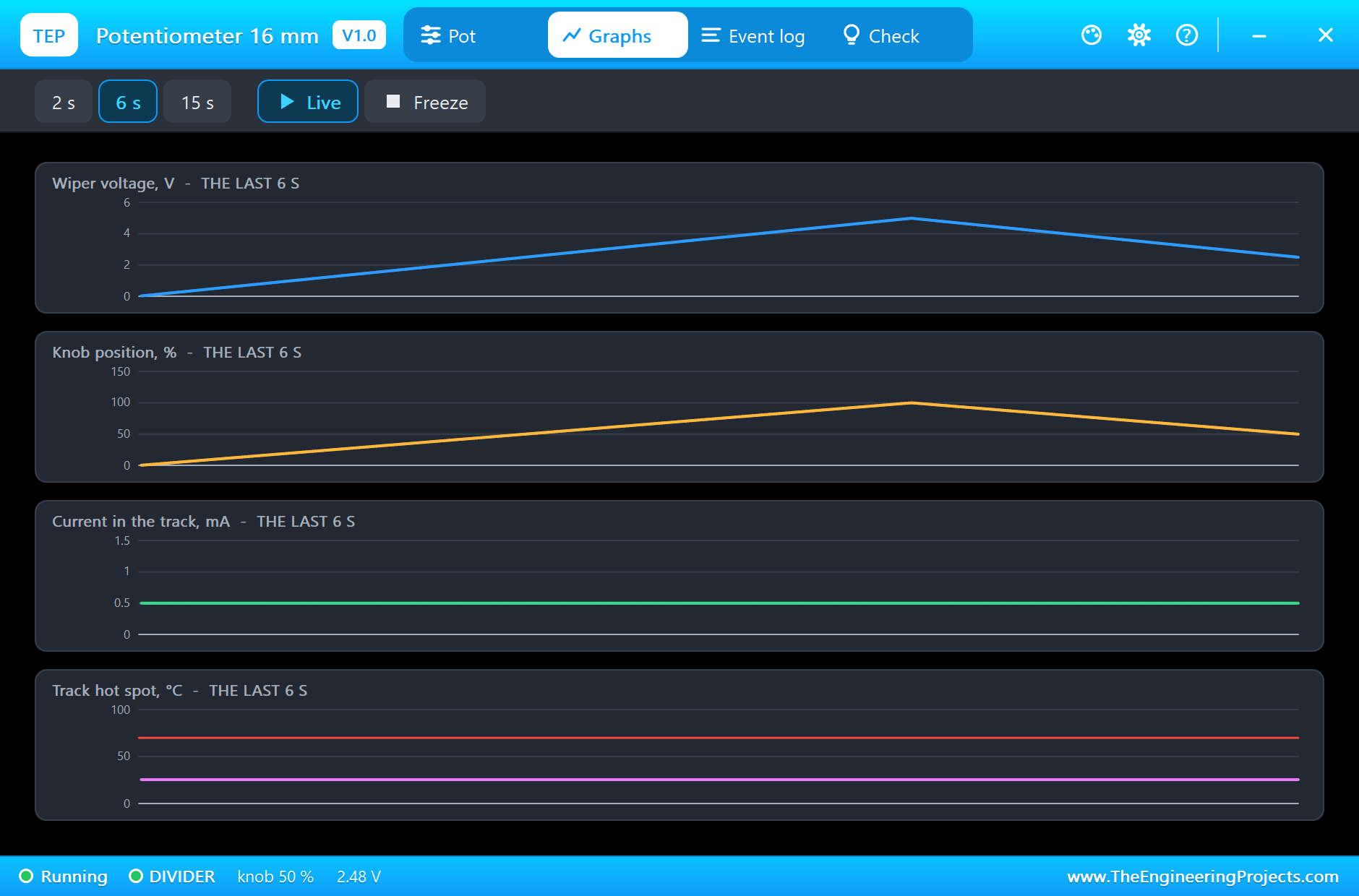
The Sweep chip turns the knob from one end to the other and back, every 8 s. It is perfect for testing a sketch over the whole range without a single click. The Graphs page shows the wiper voltage following the knob in a clean triangle, while the track current stays at 500 µA the whole time, because a divider always has the full track across the supply:
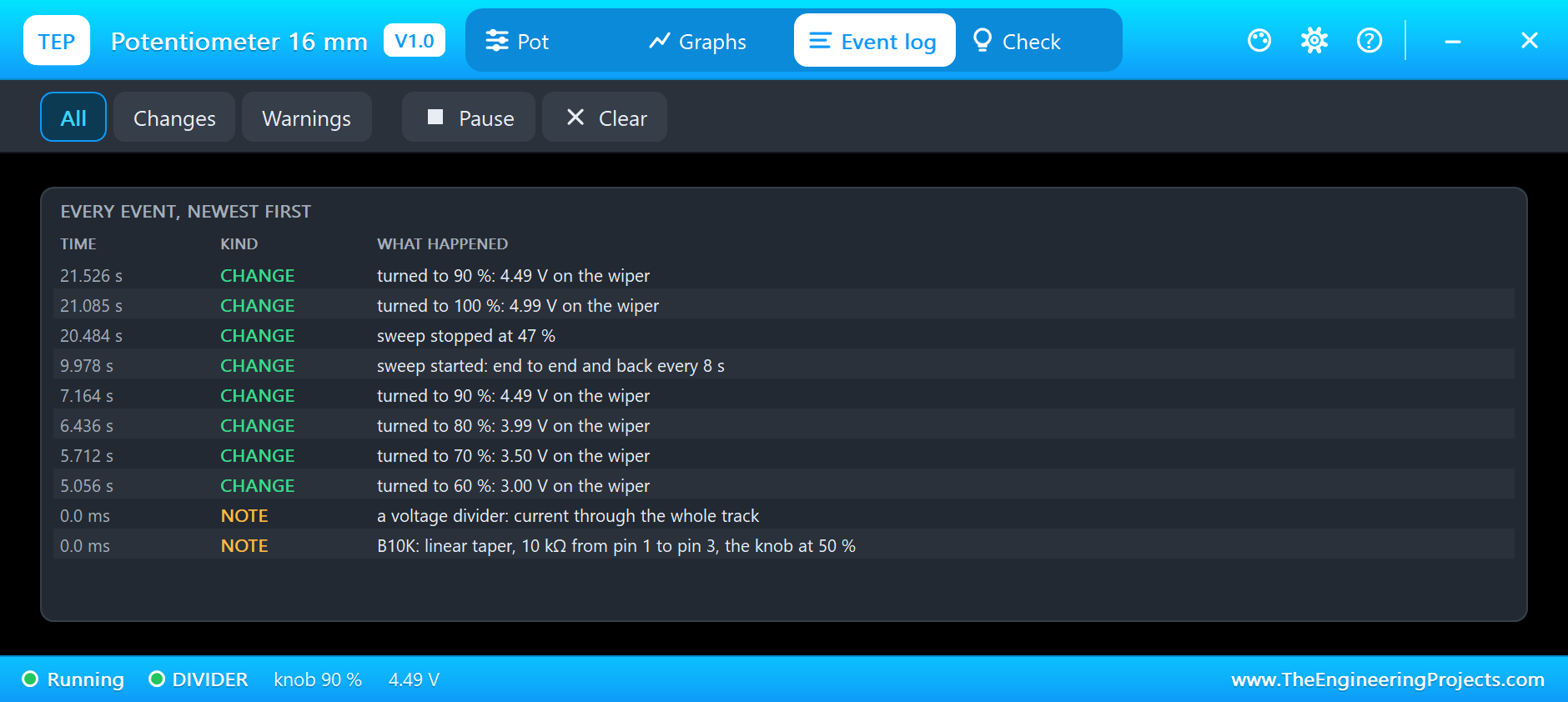
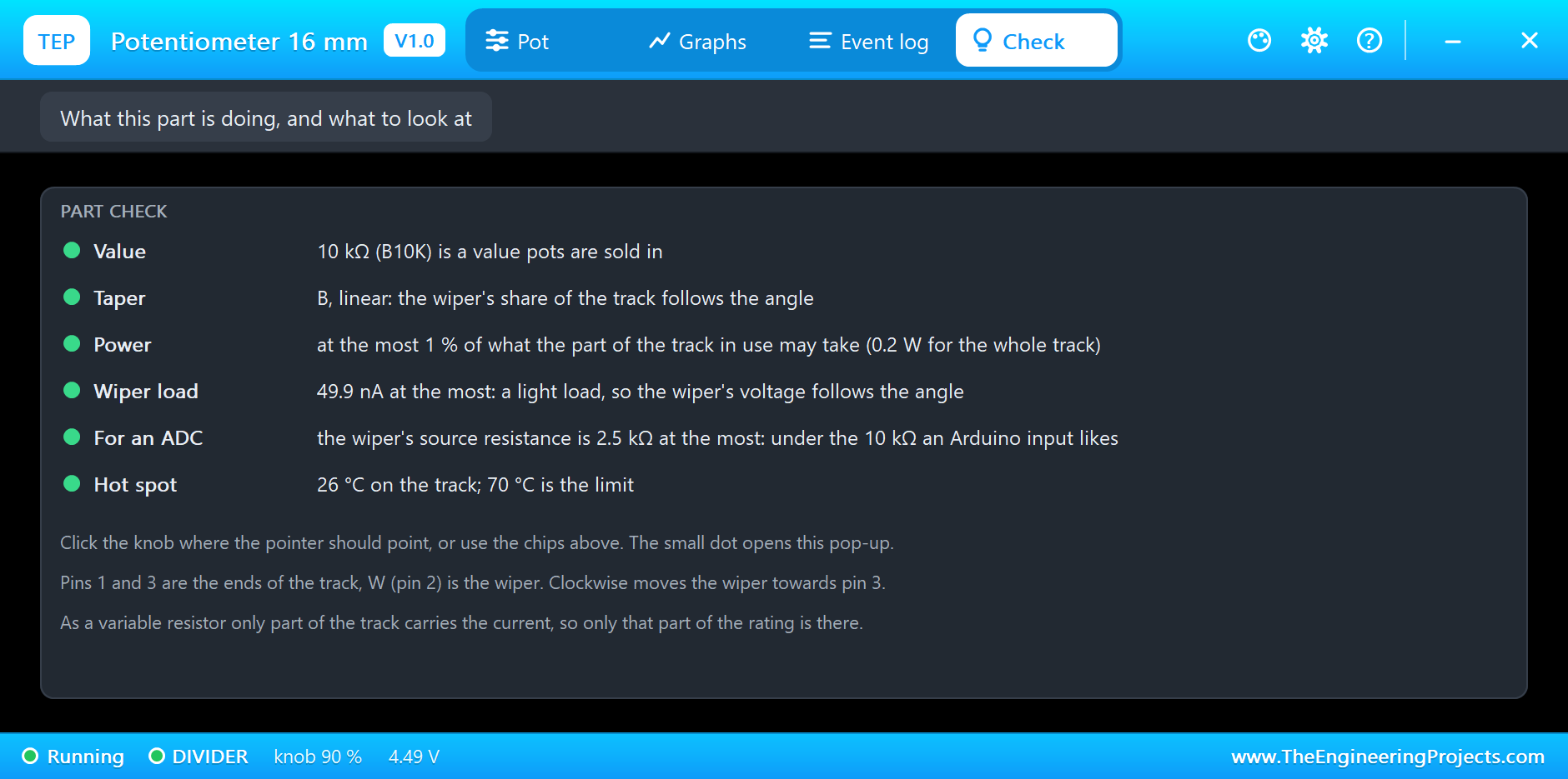
The Event log lists every turn of the knob with the wiper voltage it gave, and the start and the end of the sweep. The Check page looks at the value, the taper, the power, the load on the wiper and whether an Arduino input is happy with the source resistance:
Turning the Knob by Hand
You never need the chips, though. Click anywhere on the knob, and it turns to point at the mouse; a click in the dead zone between the end stops goes to the nearer end. We tested it with a real mouse: a click straight left of RV1's shaft turned it to exactly 20 %, the wiper fell to 1.01 V, and the yellow LED dimmed. A click on the small dot opened the pop-up and left the knob where it was:
Try It Yourself
- Change RV1 to A10K, and watch how little the LED brightens over the first half of the turn.
- Change RV2 to C10K, and see where 75 % puts the set point now.
- Rewire RV1 as a variable resistor in series with an LED, and watch the Check page warn you near the end of the travel.
- Click Sweep on RV1, and watch the alarm switch on and off once in every sweep.
- Make the hysteresis 0 in the sketch, park the level right at the set point, and see why it is there.
Ideas to Extend the Demo
- Set the speed of a DC motor with a pot and PWM.
- Move a servo to the angle of the knob.
- Use three pots to mix the colour of an RGB LED.
- Set the contrast of an LCD with the 9 mm pot.
Your Own Sketches
The demo sketch is in the zip file, and you can change it in the Arduino IDE. New to Arduino? Start with our Arduino Tutorial for Beginners. Export the compiled binary, and set the UNO's PROGRAM property to the new file. Our guide on How to get the HEX file from Arduino shows you where the file ends up.
Things to Know Before Using a Real Potentiometer
- Find the wiper: it is the middle pin. Swapping pins 1 and 3 just reverses the direction of the knob.
- Pick the taper: B (linear) for controls and Arduino inputs, A (audio) for volume.
- Mind the power as a variable resistor: only part of the track takes the current, so add a fixed resistor in series.
- Expect some tolerance: the total resistance is usually within 20 %, but a divider does not care, since it works on the ratio.
- Pots wear: a small pot is rated for about 10,000 turns, and an old one can crackle as the wiper skips.
Troubleshooting
- Clicking the knob does nothing: the simulation is not running, or the click landed outside the knob.
- The voltage goes the wrong way: pins 1 and 3 are swapped.
- The reading jumps near one end only: the value is an A or C taper. Use a B pot for an analog input.
- The track burnt: it was a variable resistor with too much current. Click New part, and add a series resistor.
- The part is not simulated:
TEPPOT.DLLis missing from MODELS and from the project folder.
Limitations of the Simulation
- The tolerance spread, the wiper's noise and its wear are left out.
- The knob stays at the nearest 5 % after Stop, even if you turned it to 47 %.
- Only rotary pots are included; trimmers and slide pots have their own libraries.
- Arduino is a name of Arduino; this library is not made or endorsed by Arduino or Labcenter.
- Tested in Proteus 8.5 in November 2026 (the demo as shipped). Proteus 7 is not supported.
So, that was all about the Potentiometer Library for Proteus. I hope the knob you can click makes your simulations feel a lot more like the bench, and that the taper and the power checks save a real pot or two. If you have any questions, ask in the comments and I will help you out. Till the next tutorial, take care and have fun!