Hello friends, I hope you all are doing great. Today, I am going to share the new Power Resistor Library for Proteus. A small resistor on a board handles a quarter of a watt or less. But some jobs need far more: a load to test a power supply, a resistor to drop a motor's current, a brake for a stepper drive, or a heater. For those jobs you will find a chunky white block with two wire legs and its value printed on the side, the cement resistor, and it is one of the toughest parts in electronics.
Power Resistor Library for Proteus
Latest version: V1.0 (November 2026, this tutorial)
Other component libraries: C945 Transistor · PC817 Optocoupler · Relay Module · Resistor · 5 mm LED · Designer Colour LED · Push Button · Active Buzzer · Electrolytic Capacitor · Ceramic Capacitor · Tantalum Capacitor · Film Capacitor · 1N4007 Diode · Zener Diode · Schottky Diode · Supercapacitor · Photodiode · RGB LED · Bridge Rectifier · Flashing LED · Bi-Colour LED · SMD LED · Slide Switch · Toggle Switch · Rocker Switch · Micro Limit Switch · Emergency Stop Switch · SMD Resistor · Resistor Network · Potentiometer · Trimmer Potentiometer · Slide Potentiometer · NTC Thermistor · DIP Switch · Fuse · Passive Buzzer · Mini Speaker · 7-Segment Display · LED Bar Graph · IR / UV LED · Small Transistors · TIP122 Darlington · N-MOSFET · P-MOSFET · PC817 Optocoupler · Filament Bulb · Power LED · Voltage Regulator · SCR and TRIAC · Inductor · Toroid Inductor · Crystal
Helping Tools
- Serial Monitor Advance: a serial terminal window for the UART of your board
- Serial Monitor Expert: the serial monitor with extra debugging tools
- LCD Library for Proteus V3.0: 16x2, 20x4 and I2C LCDs to show your readings
Our library has two of them at true scale: a 5 W part, 22 by 9.5 mm, and a 10 W part, 48 by 9.5 mm. Type a value and the print on the side follows, in the real format: 5W 10RJ, 5W 4R7J or 10W 0R47J. The body heats with the power it burns, and it runs very hot by design. Push it past its rating and it starts to glow, and if you push hard enough, the wire inside opens. The demo is a dummy load measured by the Arduino through a shunt, and we turn it up until it glows.
NOTICE: Our team has put a lot of effort into these small parts: the bodies, the animation and the pop-ups are all our own design, and you get them free. Your feedback is the fuel that keeps us going, so please tell us what you think in the comments below or in the Power Resistor board of our forum. And if our free libraries help you, you can buy us a coffee. So, let's get started with the Power Resistor Library for Proteus:
What is a Power Resistor?
Every resistor turns electrical energy into heat. A tiny resistor carrying a few milliamps makes a few milliwatts, which it loses to the air without effort. A power resistor is built to make, and survive, watts of heat. The power in a resistor is the current squared times the resistance, so doubling the current makes four times the heat. That is why the job, not the value, decides how big a resistor must be.
The white cement resistor is one of the most common kinds. Inside is a wirewound element: a resistance wire, usually a nickel and chromium alloy, wound on a ceramic core. That element sits in a rectangular ceramic case, and the space around it is filled with a cement that holds it firm, insulates it, and passes the heat to the outside. The result is cheap, rugged and happy to run far hotter than any normal component.
| Feature | The real part | In the library |
|---|---|---|
| 5 W size | 22 x 9.5 mm, axial | 924 x 400 thou, true scale |
| 10 W size | 48 x 9.5 mm, axial | 2016 x 400 thou, true scale |
| 5W 10RJ on the side | the print follows the value | |
| Heat | about 275 C at full rating | the same, then it glows |
| Failure | the wire inside opens | it opens past 700 C |
Reading the Print
The print follows the RKM code, set out in IEC 60062. The rating comes first, then the value, then a letter for the tolerance. In the value, the letter R, K or M stands in for the decimal point and gives the unit at the same time. So 10R is 10 ohm, 4R7 is 4.7 ohm, 0R47 is 0.47 ohm, 1K0 is 1 kilohm and 2K2 is 2.2 kilohm. The final letter is the tolerance: J means 5 %, K means 10 % and F means 1 %.
| Rating | Value | Tolerance | |
|---|---|---|---|
| 5W 10RJ | 5 W | 10 ohm | 5 % |
| 5W 4R7J | 5 W | 4.7 ohm | 5 % |
| 5W 0R47J | 5 W | 0.47 ohm | 5 % |
| 10W 1K0J | 10 W | 1 kilohm | 5 % |
| 10W 2K2K | 10 W | 2.2 kilohm | 10 % |
Why use a letter instead of a dot? Because a printed dot is easy to lose. A smudge or a scratch could turn 4.7 into 47, and with a power resistor that mistake could cost a fire. A letter in the middle of the number cannot vanish without anyone noticing. The same RKM style appears on circuit diagrams for the same reason.
How Hot Is Too Hot?
This surprises most people the first time. A cement resistor running at its full rating is meant to be extremely hot, well over 200 C on the surface. Our model puts it near 275 C at full power. That is fine for the resistor, but it is far too hot for the board, for the insulation of nearby wires, and certainly for fingers. So designers rarely run one near its rating. Using it at about half the rating keeps it much cooler, and makes it last far longer.
When the power goes past the rating, the temperature keeps rising. In our model the body starts to glow above 290 C, and if it reaches 700 C the wire inside breaks and the circuit opens. A real one does the same: an overloaded wirewound resistor usually fails open, sometimes with smoke and a smell of hot cement, rather than turning into a short.
Choosing the Rating
Here is a quick way to choose one. Work out the power with P = I x I x R, or with P = V x V / R, and then pick a part rated for at least twice that. In our demo, 10 ohm with 4.77 V across it burns 2.28 W, so a 5 W part is a sensible choice. At 2.2 ohm the same load burns 7.71 W, and it would want a 20 W part. Remember too that a hot resistor heats everything near it: two resistors side by side, each at half its rating, run hotter than one on its own.
Mounting a Power Resistor
Because of the heat, a cement resistor should stand off the circuit board, with a few millimetres of lead between the body and the board, and air all around it. Keep plastic parts, electrolytic capacitors and cables away from it. In a box, give it a path for the heat, or a vent. For still more power there are aluminium-cased resistors that bolt to a heatsink, the gold-coloured kind, but the idea is the same: the heat has to go somewhere.
Where Are They Used?
You will find power resistors as dummy loads for testing power supplies and batteries, as current limiting resistors for motors and lamps, as bleeders across big capacitors, as brake resistors that soak up the energy of a decelerating motor drive, and as heaters in small incubators or 3D printer beds. The low values, such as 0R1 or 0R47, are often shunts, used to measure a current by the small voltage that appears across them, which is exactly how our demo uses one.
A Note on Wirewound Parts
A wire wound into a coil has some inductance, so a wirewound resistor behaves a little like an inductor at high frequency. For power supplies and loads at DC or mains frequency that does not matter at all, but in a fast switching circuit it can. For those, designers choose metal film or special non-inductive types. Our smaller parts in the Resistor Library for Proteus and the SMD Resistor Library for Proteus cover the low power side of the family.
Features of the Power Resistor Library for Proteus
- The real look, at true scale: the white ceramic case, the cement ends, the axial leads and our small TEP signature.
- Two sizes: 5 W and 10 W.
- The print follows the value: the rating, the RKM value and the tolerance letter, exactly as on the real part.
- It heats and glows: about 275 C at full rating, a glow past 290 C, and an open wire past 700 C.
- Live value changes: the E12 chips in the pop-up step the value at Run, and the print repaints at once.
- The print read out: the pop-up explains every part of the print.
- A pop-up for every part: click the resistor at Run for the print, eight live values, graphs, an event log and a check page.
- A complete package: about 1.2 MB with the library, our Arduino UNO V4.0 and the demo, without the source code of the models.
The Power Resistors in Proteus
The devices are RESISTORPOWER5WTEP and RESISTORPOWER10WTEP in TEPPOWERRES.LIB, under Resistors, Power Resistors, with the prefix R and the model TEPPOWERRES.DLL. Search RESISTORPOWER in Pick Devices. Both have two pins, 1 and 2.
The Properties
| Property | What it does |
|---|---|
| Resistance (VALUE) | type 10, 4R7, 0R47 or 1k; the print follows |
| Tolerance, % | 5 prints J, 10 prints K, 1 prints F |
| Power rating, W | 5 or 10, and it is printed too |
| Print while stopped | the value the sheet prints while stopped; the run sets it to match |
Download Power Resistor Library for Proteus
Click the button below to download Power-Resistor-Library-for-Proteus-v1.0.zip (about 1.2 MB, without the source code of the models):
Power Resistor Library for Proteus V1.0- README.txt: installation, the demo, the properties, troubleshooting and the limits.
- Proteus Library Files:
TEPPOWERRES.LIBand ourArduinoV4TEP.LIB. - Proteus Model Files:
TEPPOWERRES.DLLandTEPARDUINO.DLL. - Arduino Code: the demo sketch.
- Proteus Simulation: the demo project, its HEX file and copies of the DLLs.
No Proteus yet? Read How to Download and Install Proteus 7 and 8. New to libraries? Follow How to Install a New Library in Proteus.
How to Install Power Resistor Library for Proteus
- Close Proteus and extract the whole zip file, for example to your Desktop.
- Copy the files from Proteus Library Files into the LIBRARY folder of Proteus.
- Copy the files from Proteus Model Files into the MODELS folder.
- Delete
TEPPOWERRES.IDXfrom the LIBRARY folder if it is there. - Start Proteus, press P and search for RESISTORPOWER.
Demo: A Dummy Load with a Shunt
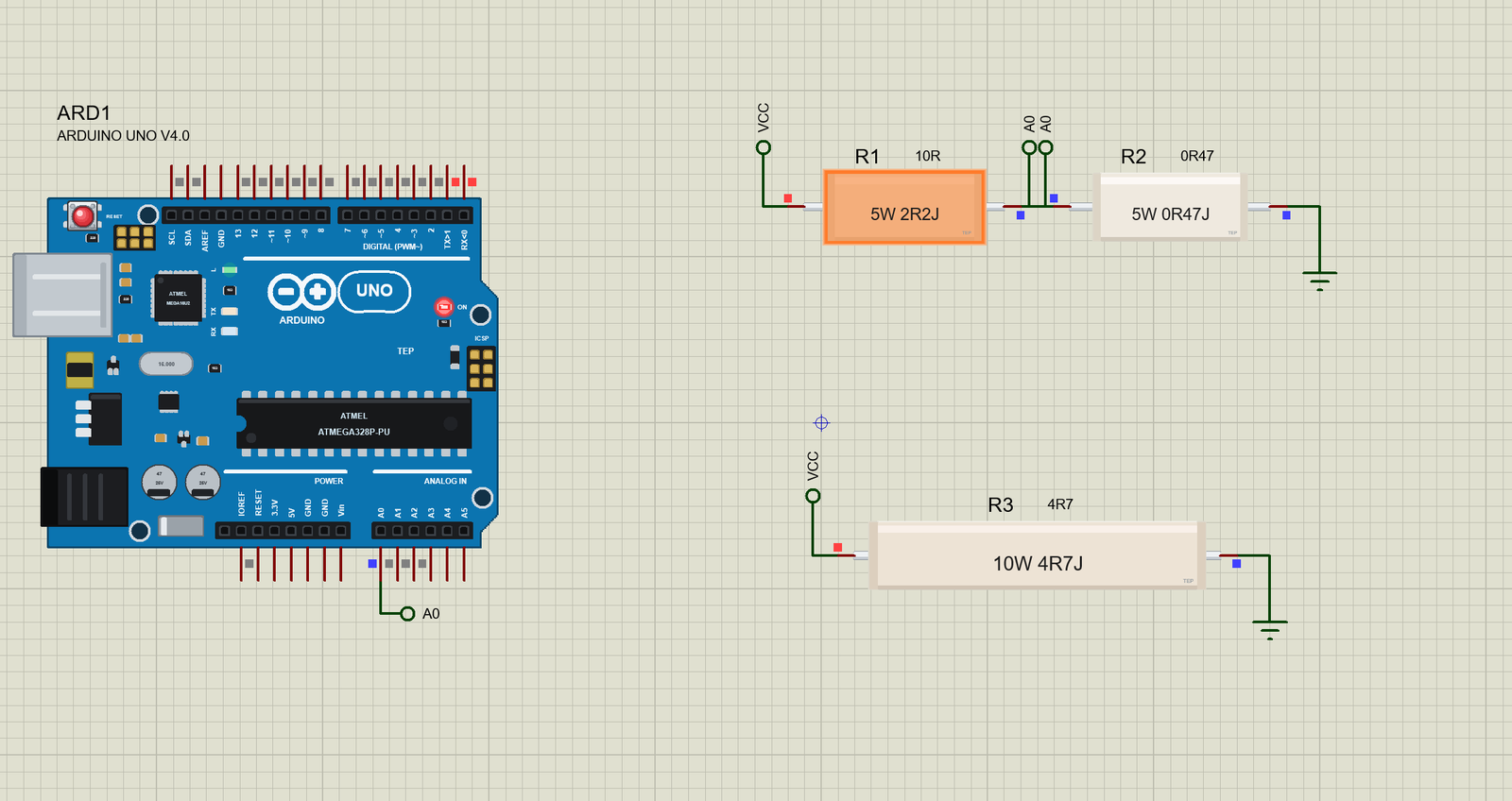
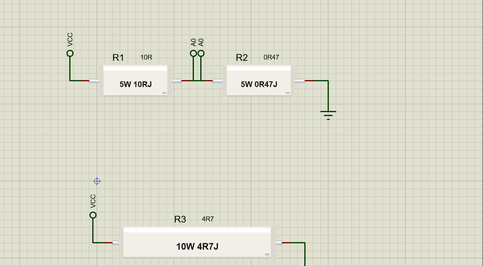
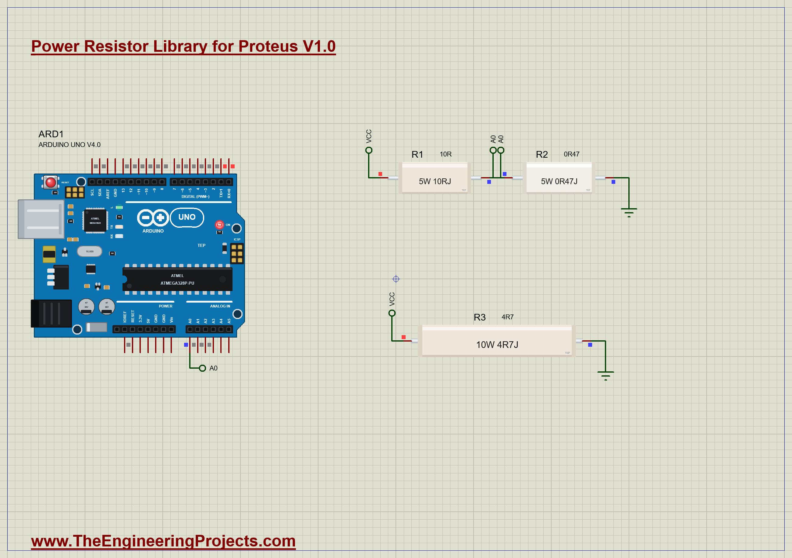
A dummy load is a resistor that stands in for a real load, to test a power supply. Ours sits on the UNO's 5 V rail. R1, a 5 W 10R, is the load. Below it, R2, a 5 W 0R47, is the shunt: the load current flows through it too, so the voltage at the top of R2, read on A0, tells the sketch the current. R3, a 10 W 4R7, is a heater across 5 V, for comparison. Open Power-Resistor-Dummy-Load-ArduinoUnoV4.pdsprj. It runs on our Arduino UNO Library for Proteus V4.0, with its built-in monitor, the same window as our TEP Serial Monitor Advance for Proteus.
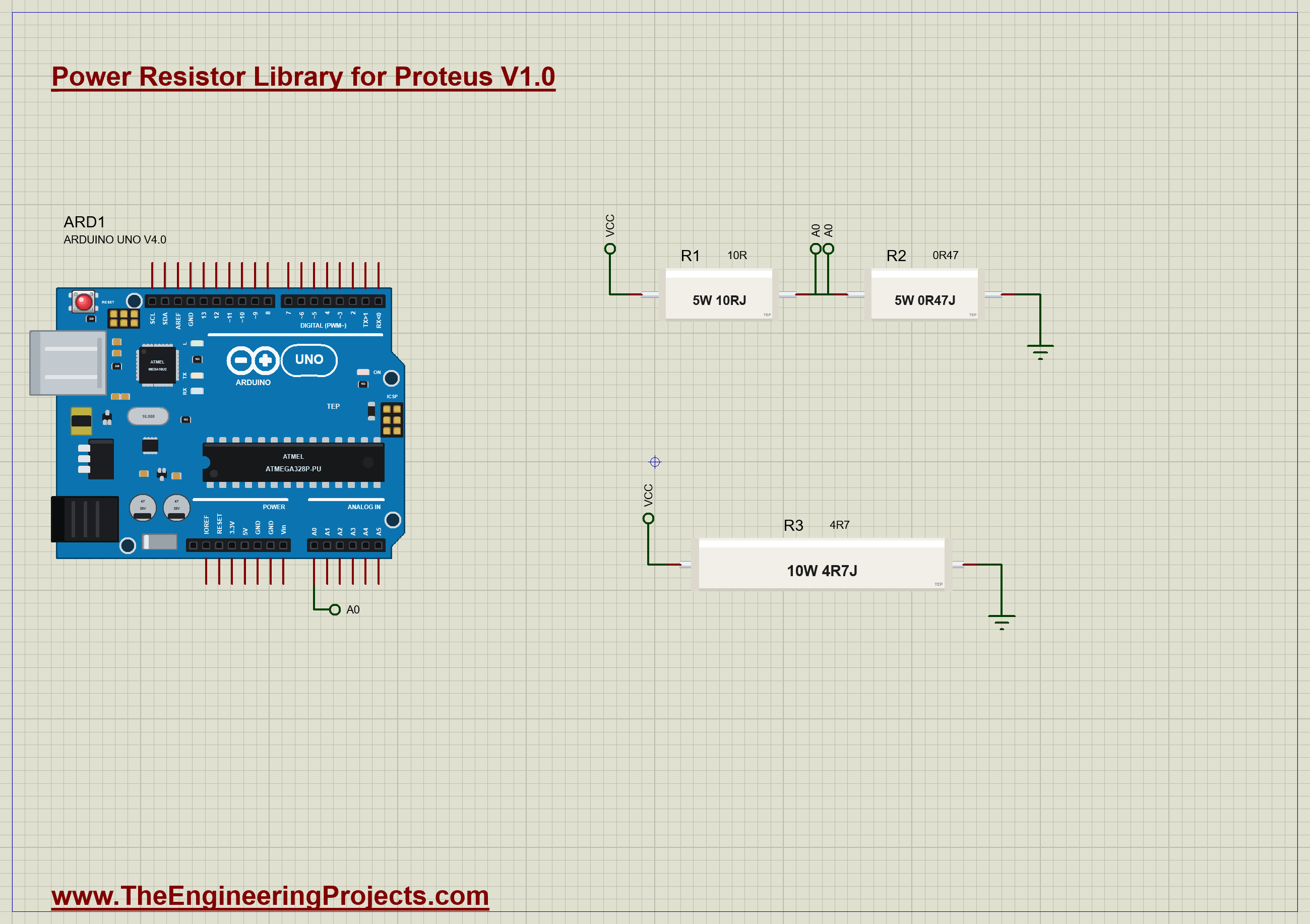
| Part | Job | |
|---|---|---|
| R1 | 5W 10RJ | the load, stepped down at Run |
| R2 | 5W 0R47J | the shunt: A0 reads I x 0.47 ohm |
| R3 | 10W 4R7J | a heater across 5 V |
The Sketch
The sketch averages 32 readings of A0, and turns the shunt voltage into a current with Ohm's law:
  float shuntVolts = readVolts();
  float amps = shuntVolts / SHUNT_OHMS;
From the current it works out the power in the load, which has the rest of the 5 V across it, and in the shunt. It prints a line when the current changes, and every ten seconds anyway:
  float loadWatts = (SUPPLY - shuntVolts) * amps;
  float shuntWatts = shuntVolts * amps;
Run the Demo
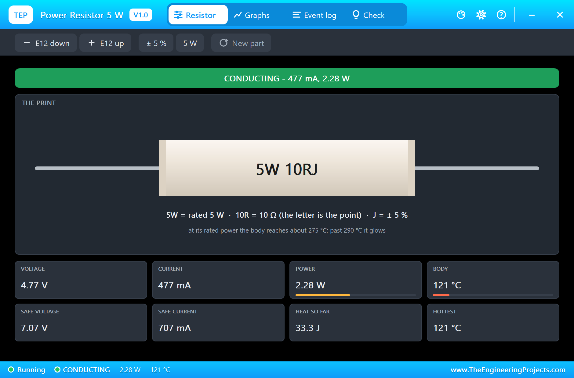
Press Run. With R1 at 10R, the load carries 477 mA and burns 2.28 W, and after a few seconds its body is at 121 C. That is less than half its rating, so it is only warm by the standards of a power resistor, but already far too hot to touch:
Here is the complete circuit, truly running:
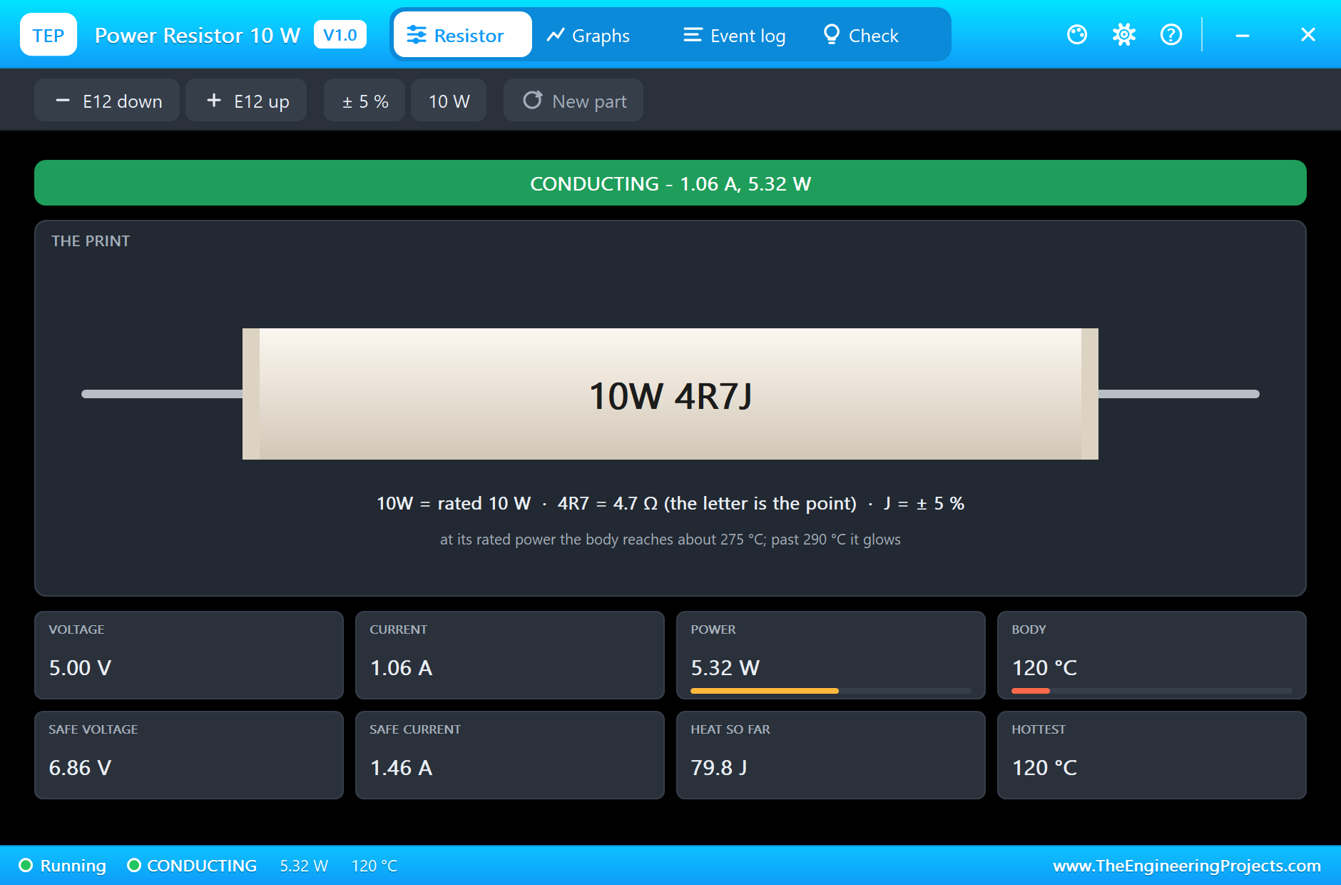
Meanwhile R3, the 10 W heater, has 5.31 W in it, about half its rating. It takes longer to warm up, because there is more of it, and in this run it settled at 155 C:
Turn Up the Load
Now click E12 down on R1's pop-up, one step at a time: 8R2, 6R8, 5R6, 4R7, 3R9, 3R3, 2R7 and 2R2. With each step the print on the body changes, the current climbs, and the power climbs faster still. At 3R9 the load passes its 5 W. At 2R2 it carries 1.87 A and burns 7.71 W, more than one and a half times its rating. Give it half a minute, and the body starts to glow:
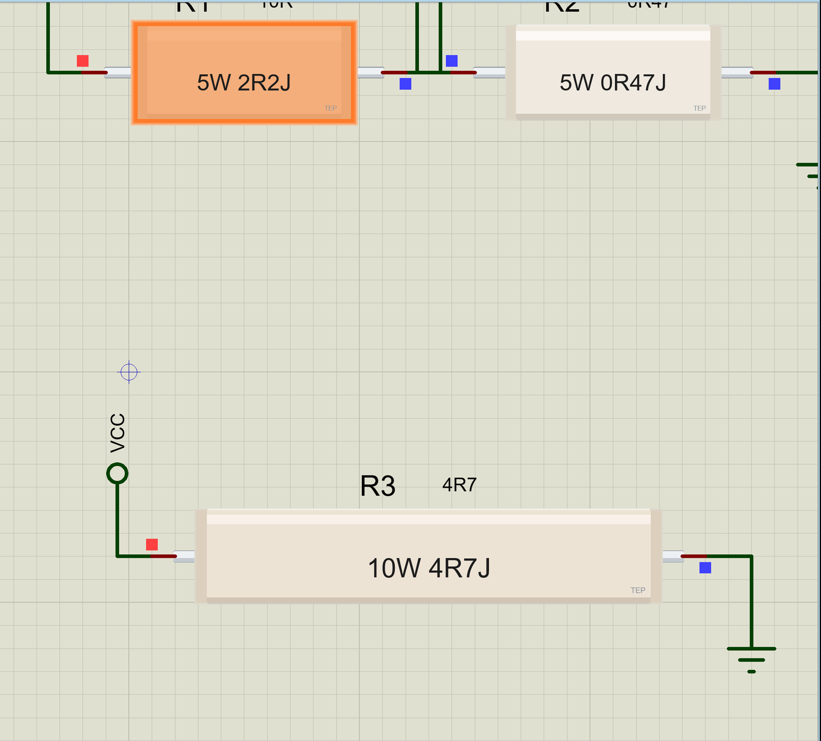
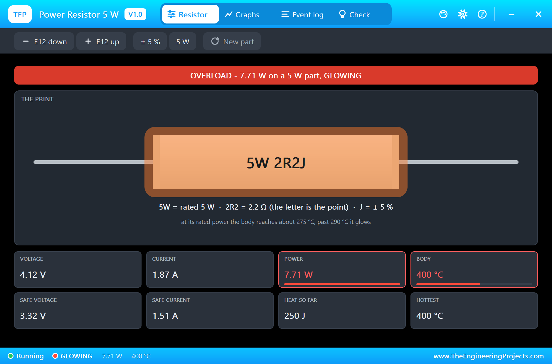
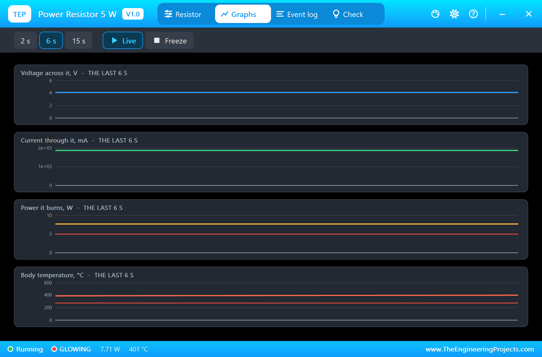
The Graphs tab shows each step as a jump in the current and the power, and the temperature curving up after them, well past the line of the full rating:
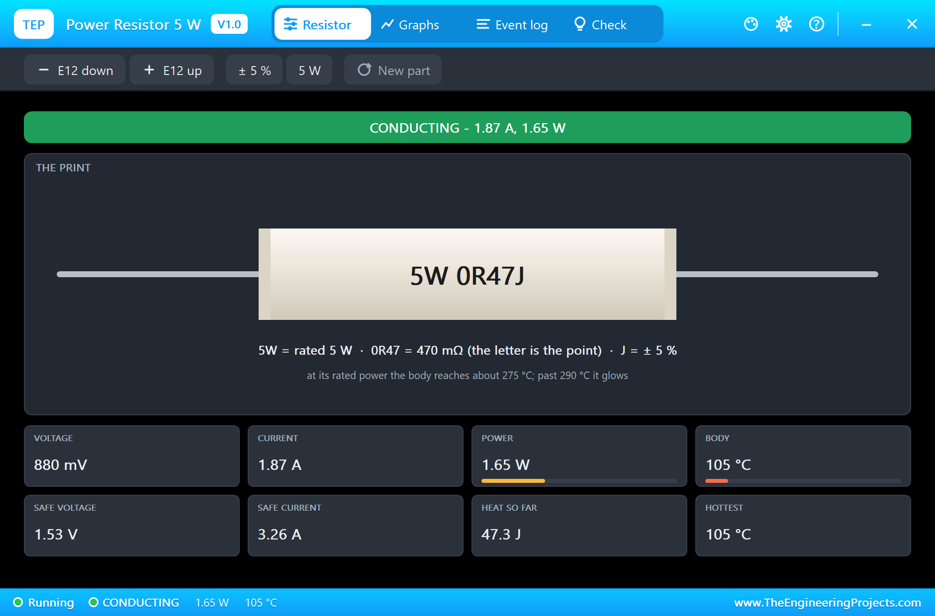
The shunt has an easier time. It carries the same 1.87 A, but with only 0.47 ohm it burns 1.65 W, a third of its rating, and runs at 104 C:
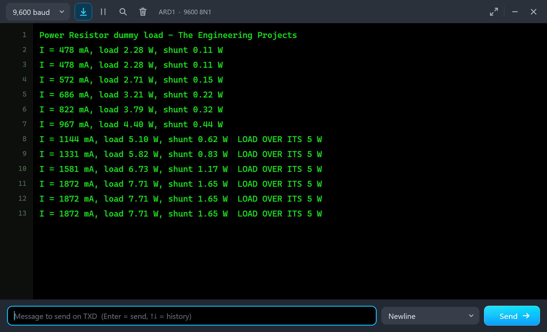
The monitor tells the same story from the Arduino's side, a line for every step. From 3R9 onwards it flags the load as over its 5 W:
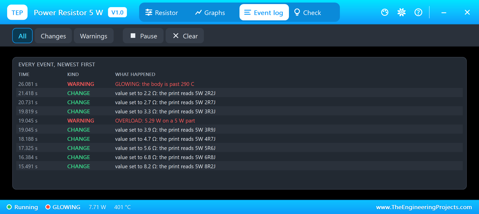
The Log and the Check Page
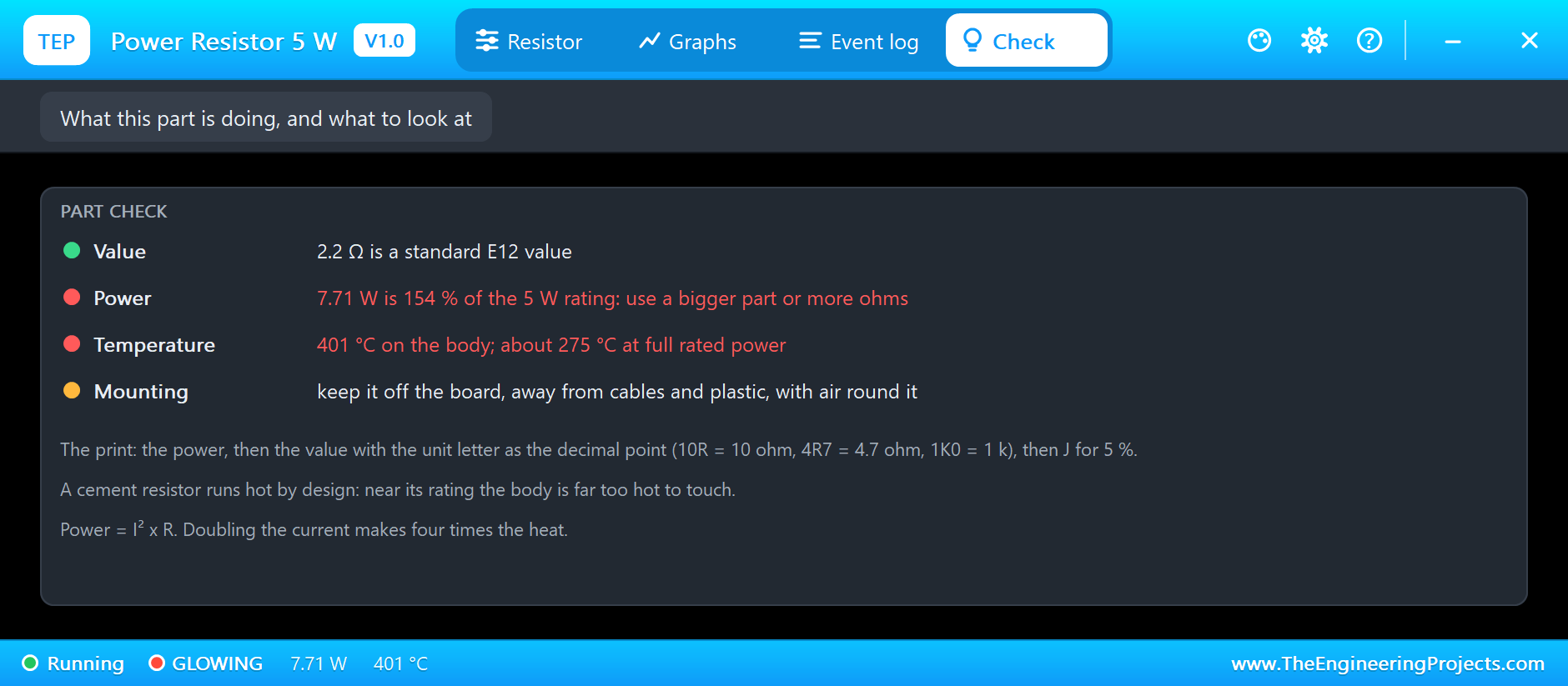
The Event log lists every value change with its new print, the overload, and the moment the body began to glow. The Check page judges the power against the rating and the temperature against the full rating heat, and reminds you how to mount a hot part:
Try It Yourself
- Keep stepping R1 down past 2R2, and find the value at which it burns out. Then click New part.
- Change R1 to a 10 W part with the power chip, and see it stay white at 2R2.
- Change the shunt to 0R1, and see how much smaller the reading on A0 becomes.
- Set R1's tolerance to 10 %, and watch the J in the print turn into a K.
- Work out the power in R1 for each step by hand, and compare it with the monitor.
Ideas to Extend the Demo
- Switch the load with a MOSFET from a PWM pin, and make an adjustable electronic load.
- Discharge a battery through a power resistor, and log the capacity it delivers.
- Build a small heater with a temperature sensor and a thermostat in the sketch.
- Add a fan that the sketch turns on when the load passes half its rating.
Your Own Sketches
The demo sketch is in the zip file, and you can change it in the Arduino IDE. New to Arduino? Start with our Arduino Tutorial for Beginners. Export the compiled binary, and set the UNO's PROGRAM property to the new file. Our guide on How to get the HEX file from Arduino shows you where the file ends up.
Things to Know Before Using a Real Power Resistor
- Never touch one that has been running: near its rating the body is far over 200 C.
- Use about half the rating: it runs cooler and lasts much longer.
- Stand it off the board: leave lead length and air round the body, and keep plastic and cables away.
- Check the voltage rating too: high value power resistors have a voltage limit as well.
- Avoid wirewound types in fast switching circuits: their inductance can cause trouble there.
Troubleshooting
- The body turned dark and stopped conducting: it burnt out. Click New part, or use a bigger rating.
- The label beside the part still shows the old value: that label is what you typed. The print on the body follows the live value.
- The stopped print differs from the value: the Check page says which Print while stopped to pick, and a run sets it for you.
- A0 reads almost nothing: a shunt makes a small voltage on purpose. Average many readings, as the sketch does.
- The part is not simulated:
TEPPOWERRES.DLLis missing from MODELS and from the project folder.
Limitations of the Simulation
- The heat model uses one time constant for the whole body; a real one heats from the inside out.
- The inductance of the wire and the temperature coefficient are left out.
- The glow and the burn-out temperatures are typical, not those of one maker.
- Arduino is a name of Arduino; this library is not made or endorsed by Arduino or Labcenter.
- Tested in Proteus 8.5 in November 2026 (the demo as shipped). Proteus 7 is not supported.
So, that was all about the Power Resistor Library for Proteus. I hope you enjoy watching that white block glow, and that it leaves you with a healthy respect for watts, and for the cement resistors that soak them up. If you have any questions, ask in the comments and I will help you out. Till the next tutorial, take care and have fun!