


PIC Microcontroller Projects


Hello friends! This page brings together our PIC microcontroller projects in a learning sequence. We will start with the controller, programming tools and a basic LED, then move through displays, inputs, analog measurements and motor-control exercises. Each linked tutorial gives you a practical next step instead of leaving you with an unrelated list of projects.
If you are beginning with PIC devices, work through one small circuit at a time. Read the explanation, identify the important connections, build or simulate the example, and record what you observed. Understanding why a simple project works is more useful than collecting several HEX files you cannot adapt.
Many tutorials in this collection were originally written around older PIC devices and development tools. Their core ideas remain useful, but the exact compiler, configuration settings and device registers matter. We will distinguish those historical choices from the decisions you need to make for your own project.
Choose a Learning Path
| Stage | Exercise | Main skill |
|---|---|---|
| 1 | Controller and toolchain setup | Match device, compiler and programmer |
| 2 | LED blinking | Power, clock, configuration and GPIO |
| 3 | Character LCD | Interface timing and pin mapping |
| 4 | Keypad input | Scanning, debouncing and input events |
| 5 | ADC and temperature display | Reference voltage, scaling and measurement validity |
| 6 | Servo or stepper control | Timing and a suitable power interface |
| 7 | Combined access-control exercise | State management and failure handling |
You can enter at a later stage if you already understand the preceding skills. However, return to a minimal GPIO project when a complicated circuit stops responding. A known working baseline helps you distinguish a basic configuration problem from an application bug.
Learn What the Microcontroller Actually Does

A microcontroller executes a stored program and communicates with the outside world through its peripherals. GPIO, timers, analog converters and serial interfaces each have their own configuration and operating limits. The name PIC covers many devices, so a feature on one family member is not automatically present on another.
- Getting Started with Microcontrollers explains the general relationship between program execution, memory and external signals.
- Getting Started with PIC Microcontrollers narrows that introduction to the PIC family and its development workflow.
- Functions Available in PIC18F452 introduces the particular device used in several tutorials here.
- PIC C Compiler Comparison helps you understand why compiler-specific examples differ.
For the PIC18F452, keep the Microchip PIC18FXX2 datasheet beside the tutorial. Use it to identify package pins, peripheral registers, electrical limits and configuration options. A tutorial should explain the path through those details, while the device documentation defines the actual hardware.
Do not treat a PIC18F452, PIC18F4550 and PIC16F877A as interchangeable merely because some packages have the same pin count. Register layouts, peripheral choices and configuration bits differ. Start a new project for the intended device and review the code before changing the chip selection.
Understand IDEs, Compilers and Programmers
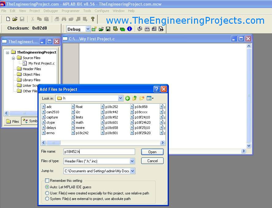
An IDE organizes source files, build settings and debugging. A compiler translates a programming language into machine code for the selected target. A programmer transfers that program to the physical microcontroller. These roles cooperate, but they are not the same tool.
The older articles refer to MPLAB IDE and MPLAB C18. MPLAB is not itself synonymous with a C compiler, and installing an IDE does not restrict you to assembly language. Language support depends on the configured toolchain.
For a new installation, select a supported IDE and compiler combination for your exact PIC device. When maintaining a C18 project, expect migration work if you move to a different compiler: headers, configuration syntax, interrupt declarations and library routines can change.
- How to Install MPLAB Software in Windows preserves the original IDE installation workflow.
- How to Install MPLAB C18 Compiler in Windows explains the historical compiler used by the accompanying examples.
- Getting Started with MPLAB introduces project creation and the build process.
Other toolchains, including mikroC and CCS, provide their own language extensions and libraries. A familiar function name such as an LCD write routine may belong to one compiler's library. Copying it into another compiler without the required implementation does not make it portable C.
Prepare a Minimum Working Circuit
Before adding a sensor or display, establish the MCU's power, reset, clock and programming connections. Connect every required supply and ground pin, place appropriate decoupling close to the device, and check the operating voltage against the datasheet.
The oscillator arrangement must agree with the configuration bits and any frequency assumptions in the program. A delay function compiled for one clock frequency will produce a different real delay if the hardware runs at another frequency.
Keep programming connections accessible. Check whether your programmer powers the target or expects an external target supply; do not assume those arrangements are identical. Signals attached to programming pins can interfere with programming if their loading or drive state conflicts.
Make a small project record containing the MCU part number, package, supply voltage, clock source, compiler version and programmer. Those details often explain why the same-looking code behaves differently on two boards.
Project 1: Blink an LED
Begin with LED Blinking with a PIC Microcontroller. The visible result is simple, but the project checks a large part of the development chain: successful compilation, programming, execution, clock configuration and output-pin operation.
Choose a GPIO pin that is available in the selected configuration. Configure its direction and any relevant analog function before using it as a digital output. On PIC devices with output latch registers, understand the difference between writing an output latch and reading a port.
Calculate the LED resistor. With an assumed 5 V output, 2 V LED forward drop and 5 mA target current, R = (5 - 2) / 0.005 = 600 ohms. A nearby suitable standard value can be selected after checking the real output voltage and device limits.
A useful extension is to change the blink interval deliberately and predict the visible effect before rebuilding. If the observed period does not scale as expected, inspect the loaded binary and clock assumptions instead of immediately adding more code.
Project 2: Add a Character LCD
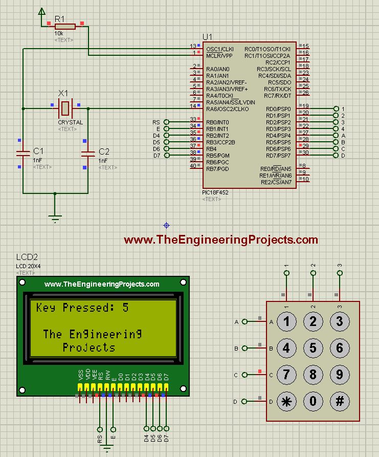
Continue with LCD Interfacing with PIC in Proteus. An LCD makes later measurements visible and teaches the importance of a consistent mapping between software signal names and physical connections.
Check the RS, Enable and data-pin order, the selected four-bit or eight-bit mode, contrast adjustment and display dimensions. A lit backlight only proves something about the backlight circuit; it does not prove that the LCD controller was initialized correctly.
Write a fixed message first. Then display a changing number and handle the leftover characters when the new value is shorter. Keeping display formatting separate from measurement code makes both easier to diagnose.
For timing analysis, consider a conventional PIC18 instruction clock derived from FOSC/4. At an assumed oscillator frequency of 20 MHz, the instruction-cycle frequency is 5 MHz and the cycle time is 0.2 microseconds. This is a useful starting point, but not every instruction or peripheral operation takes exactly one cycle.
Project 3: Read a Keypad
Interfacing a Keypad with PIC introduces a matrix of switches. The controller drives one part of the matrix and reads another to identify a row-and-column combination.
Use defined input states rather than floating pins. Mechanical contacts can bounce, so a single press may produce several transitions. Debouncing establishes when the input is stable, while event handling decides whether a held key should be reported once or repeatedly.
Test press, hold, release and two-key combinations. A basic matrix without isolation diodes may produce ambiguous combinations or ghosting. A tutorial that demonstrates one key at a time should not be assumed to handle every multi-key combination.
Display the detected key on the LCD before adding a password comparison. This isolates the electrical input and scanning logic from later application decisions.
Project 4: Measure an Analog Voltage
Display an ADC Value on an LCD Using PIC connects measurement with presentation. Begin by displaying the raw ADC code, then convert it into an engineering quantity with explicitly stated assumptions.
For an ideal 10-bit ADC, there are 1024 code intervals. With a 5 V reference, the nominal interval width is 5 / 1024 = 4.883 mV. An approximate voltage reconstructed from code 512 is therefore 2.5 V on that scale.
Some endpoint display formulas use 1023 to map the largest code exactly to the reference voltage. Explain which convention you use. Neither convention removes reference tolerance, sensor error or the quantization uncertainty of the conversion.
Check analog pin configuration, reference selection and acquisition time. The sample-and-hold input needs time to settle from the connected source. A high-impedance source may require more care than a low-resistance potentiometer.
Project 5: Add a Temperature Sensor
Interfacing LM35 with PIC applies ADC scaling to a physical quantity. Follow the exact sensor's transfer characteristic and wiring rather than treating every three-pin temperature sensor as equivalent.
For a hypothetical sensor producing 10 mV per degree Celsius, a measured 250 mV corresponds to 25 degrees Celsius. With the 5 V, 10-bit ADC example above, one code represents approximately 0.488 degrees on that scale. Printing two decimal places does not make the complete system accurate to 0.01 degrees.
Record the reference voltage, sensor placement and settling time when comparing results. Also decide how the program distinguishes a plausible temperature from a disconnected or saturated input. A displayed number alone does not establish a valid measurement.
Project 6: Control Motion
- Servo Motor Control with PIC in Proteus introduces repeated control pulses and their timing.
- Stepper Motor Control Using PIC introduces coil sequences and a suitable driver interface.
A hobby servo's signal connection carries a command; it does not supply the motor's operating current. Use a supply and wiring appropriate to the servo, with a shared signal reference where required. Avoid assuming that a simulator's unloaded motion demonstrates adequate physical power delivery.
Likewise, a stepper motor needs a driver suitable for its winding current and inductive behavior. The microcontroller generates a sequence, but its GPIO pins are not a substitute for a motor power stage.
As a timing exercise, an assumed 1.5 ms pulse in a 20 ms period has a 7.5 percent duty ratio. That calculation describes the pulse train; the corresponding servo angle depends on the actual servo's accepted range and calibration.
Project 7: Combine Inputs and Outputs
- Electronic Door Lock Using PIC combines user input with an output mechanism.
- Password Protection Using PIC explores entry, comparison and application state.
Build these as controlled learning exercises after validating the keypad, display and output interface separately. Define states such as waiting, collecting input, checking, accepted and rejected. Explicit states are easier to review than several unrelated flags and blocking delays.
Bound the input buffer and handle cancel, timeout and incorrect entry. Decide what happens at reset and when power fails. A classroom password comparison is not, by itself, a complete security design for an occupied building or valuable equipment.
Keep the output action time-bounded and handle feedback if the application needs to know whether a mechanism actually moved. A command to energize a driver and confirmation of physical motion are different observations.
Make Each Project Reproducible
- Write the expected behavior before changing the circuit.
- Save the source, compiler settings and schematic together.
- Record the exact program file loaded into the simulator or device.
- Change one subsystem at a time and keep a working baseline.
- Log measured voltages, timing and failure symptoms instead of relying only on impressions.
- Repeat startup and boundary conditions, not just one successful mid-run action.
Simulation is useful for examining logic and firmware flow, but its models may omit supply noise, connector faults, real driver limits or mechanical behavior. Use it to answer defined questions and then check the relevant physical assumptions on hardware.
A failed first attempt does not necessarily mean that you made a careless mistake. It can expose an incomplete example, a version difference or an unsuitable component. Reduce the problem until you can explain the first point at which observed behavior differs from expected behavior.
Build One Timing Calculation You Can Reuse
Timers connect many projects in this collection. They can schedule a keypad scan, pace a display update or generate a control interval without spending the entire program in a delay loop. Start by writing down the timer's clock source and prescaler instead of copying a reload value with no explanation.
As an illustrative calculation, take the 20 MHz oscillator example and a timer clocked at FOSC/4. Its starting clock is 5 MHz. With an assumed 1:8 prescaler, each timer increment takes 8 / 5,000,000 = 1.6 microseconds.
A nominal 10 ms interval therefore needs 10,000 / 1.6 = 6250 increments. For an ideal 16-bit overflow timer, the starting count would be 65536 - 6250 = 59286. The selected timer must actually support the assumed clock and prescaler arrangement.
Interrupt latency and the way the timer is reloaded can add timing error. A compare-based interval or carefully designed reload scheme may be preferable when accurate repetition matters. Measure the resulting waveform rather than presenting the arithmetic as proof of exact hardware timing.
Keep interrupt handlers short. Record an event or update a small piece of state, then perform slower formatting and display work in the main application when appropriate. This separates time-sensitive acquisition from operations that may take much longer.
Once you can explain this calculation and its assumptions, apply the same method to a new interval. You are then adapting a project from its timing requirements instead of relying on an unexplained constant.
Troubleshooting and Project Review
| Symptom | First checks |
|---|---|
| No program activity | Power, reset, oscillator, configuration and correct device selection |
| Build succeeds but behavior never changes | Program-file path and actual programming result |
| Digital input or output does not behave | Direction, analog function selection and pin conflicts |
| LCD shows blocks or nonsense | Contrast, initialization timing and data order |
| ADC reading is unstable | Reference, acquisition time, source impedance and grounding |
| Resets during motor movement | Power supply, load transients, wiring and driver interface |
When asking for help, include the device, compiler, supply, clock, relevant schematic and the smallest code example that reproduces the problem. State what you expected and what happened instead. These details allow another reader to investigate the same question.
Frequently Asked Questions
Must I buy every component before starting?
No. Begin with the chosen MCU, a suitable programming method and a minimal output exercise. Add parts as the next project requires them.
Can I use a different PIC from the tutorial?
Often, but it is a porting task. Review the pinout, registers, configuration, peripheral availability and electrical requirements rather than changing only the project name.
Is MPLAB the compiler?
MPLAB IDE organizes the development workflow. A selected compiler toolchain performs the language translation. Older C18 instructions describe a specific historical combination.
Should I learn assembly before using C?
You can begin with C while learning the hardware concepts. Understanding registers, timing and the generated program's behavior remains useful regardless of source language.
When should I move to the next project?
Move on when you can explain the current wiring and code, reproduce its result, and identify its important limits. That understanding makes the next interface much easier to build.

Tags


AOA, m final year student of EE.
and my FYP is STATCOM
plzzzzzz i vl b grate ul if u help me in its coding.
VSC and PIC Connection regarding load and capacitors bank.
1 reply
Add me on skype or call me on my number, both are given in contact us page , n let me know the details of your project, will surely help you out.
i'm final year student of EE.
i need a help..
plz help me to write micro c code for receive message.
plz help me.
1 reply
Hi,
Send us a message on Skype and we will help you out.
Thanks.
1 reply
my Skype id rosan or tsrosan email id trosa90@gmail.com
1 reply
My Skype id is "theenggprojects" . Send me a message there. Thanks.
hi sir,my project is smart notice board using gsm sim900 interface with pic16f887 with tft display.i have use microc code send sms from gsm to mobile it will receive bt i dont no how to send sms mobile phone to gsm module..it will display on tft lcd.please help me to how to receive message .....?
1 reply
Hi,
Add me on Skype and we will discuss it in detail. My Skype id is theenggprojects.
Thanks.
Dear Syed,
Can you please share a code for creating a menu & sub-menu on 16 x 2 LCD using PIC 16F877A.
Thanks.
tnx for shering ur knowledge and i would like to give me so semister project ideas on electrical power system stream plz
please i need help with interacting pic16f877a with both passive infrared and light dependent resistor to control street light intensity using pulse width modulation
2 replies
Kindly add me on Skype and we will discuss it in detail. My Skype id is theenggprojects.
Thanks.
HELLO , how far are you with this project?
dear syed,
I need to create a prototype of automatic welding machine using siemens plc help me please.
1 reply
Add me on Skype and I will help you out. My Skype id is theenggprojects.
i am student of electrical engineering ,we work on piezoelectric footsteps power generation using pic microcontroller .can you help in coding of pic16f877.
Hi, please i want to write codes on PIR (passive Infra red) sensor using C language, thank you.
dear sir! i have problem while uploading hex file to arduino mcu in proteus, arduino pro mini, simulino lilypad etc showing "initial contents of data EEPROM" what to do with this problem in protesu???
dear sir! i have problem while uploading hex file to arduino mcu in proteus, arduino pro mini, simulino lilypad etc showing "initial contents of data EEPROM" what to do with this problem in proteus???
Hii I am final year student of entc I want to write a code for pH sensor in using c language
Thank you
Comments
22