Hello friends, I hope you all are doing great. Today, I am going to share the M5StickC PLUS2 Library for Proteus. The StickC Plus2 from M5Stack is a tiny orange computer, about the size of a thumb, with an ESP32, a bright 1.14 inch colour display, three keys, a buzzer and a battery, all sealed in a neat case. Makers love it because it needs no wiring and no soldering to start. With this library it runs your ESP32 Arduino sketch in Proteus 8.5, with the display, the M5 key and the red LED working on the part.
M5StickC PLUS2 Library for Proteus
Latest version: V1.0 (November 2026, this tutorial)
Other ESP32 boards and modules: ESP32 DevKit V1 · ESP32-DevKitC V4 · ESP32-S3 DevKitC-1 · ESP32-C3 SuperMini · ESP32-C6 DevKitC-1 · TTGO T-Display · T-Display S3 · XIAO ESP32-C3 · XIAO ESP32-S3 · ESP32 Feather V2 · QT Py ESP32-S3 · ESP32-C5 DevKitC-1 · Olimex ESP32-POE · FireBeetle 2 ESP32-E · T-Call SIM800L · T-SIM7600 · T-Beam Supreme · ESP32-2432S028 CYD · M5Stack AtomS3 · M5Stack Core2 · LilyGO T-Deck · LOLIN S2 Mini · Heltec WiFi LoRa 32 V3 · LilyGO T-Beam · ESP32-CAM · ESP32-WROOM-32 · AirLift WiFi Shield · AirLift ESP32 Breakout · WT32-ETH01
Temperature and weather sensors: DHT11 / DHT22 · DS18B20 · BME280 · BMP280 · SHT31 · AHT20 · BME680 · MLX90614 · MAX6675
Helping Tools
- Laptop WiFi Monitor: a laptop on the Wi-Fi of your design: a browser, a TCP / UDP terminal and ping
- Mobile WiFi Monitor: a smartphone that opens the pages of your board and sends it commands
- Serial Monitor Advance: a serial terminal window for the UART of your board
For the demo we built a climate badge, a small watchman for a server room, a greenhouse or a store. An SHT31 on the Grove socket measures the temperature and humidity. The screen shows them in big digits, turns red when the air is too damp, and draws a graph at the press of a key. A phone on the same Wi-Fi reads the numbers from a small web page.
NOTICE: Proteus has no ESP32 model, so our team has put a lot of effort into building this board ourselves: the StickC's pins, keys, LED, display and Wi-Fi are all our own model, and your sketch compiles with our free TEP Boards for Proteus add-on. Your feedback is the fuel that keeps us going, so please tell us what you think in the comments below or in the M5StickC PLUS2 board of our forum. And if our free libraries help you, you can buy us a coffee. So, let's get started with the M5StickC PLUS2 Library for Proteus:
What is the M5StickC PLUS2?
The StickC Plus2 packs a whole gadget into a tiny case. Inside is an ESP32-PICO-V3-02, with two 240 MHz cores, Wi-Fi, Bluetooth, 8 MB of flash and 2 MB of PSRAM. The front has a 135 x 240 ST7789V2 colour display and the big orange M5 key, which is button A. There are two keys on the sides, a red LED that shares its pin with an IR emitter, a passive buzzer, a microphone, an MPU6886 motion sensor, a BM8563 clock and a 200 mAh battery. One end has USB-C and a Grove socket, and the other an 8-pin HAT socket for M5Stack's small add-on boards.
| StickC Plus2 | TTGO T-Display | ESP32 DevKit | |
|---|---|---|---|
| Display | 1.14 inch, 135 x 240 | 1.14 inch, 135 x 240 | none |
| Case | yes, with a battery | bare board | bare board |
| Keys | A, B and power | two | BOOT, EN |
| Connect sensors by | Grove and HAT | pin headers | pin headers |
| Best for | finished gadgets, wearables | desk projects | prototypes |
What Is New in the Plus2?
The older StickC Plus used a power chip, the AXP192, to turn the display and the rest of the board on. The Plus2 drops it. A HOLD pin on GPIO4 now keeps the power on: press the power key, and your sketch has a moment to set HOLD HIGH, or the stick turns off when you let go. It is the first line in our setup(). This also makes the Plus2 simpler to drive, because the display's backlight is now an ordinary pin. If you know our TTGO T-Display Library for Proteus, the display code here will look very familiar.
Features of the M5StickC PLUS2 Library for Proteus
- The stick as it looks: the orange case with the black display panel, the M5 key, the side keys, USB-C, the white Grove socket and the HAT socket, with our small TEP signature.
- Your sketch: a .hex for "M5StickC PLUS2 (TEP Proteus)" with the real GPIO numbers - analogRead 0 to 4095, analogWrite and ledc PWM, attachInterrupt, tone, Serial, Wire and SPI.
- The display on the part: the ST7789V2 with Adafruit's library, 240 x 135 pixels in full colour.
- The keys and the LED: the M5 key, the red LED on GPIO19 and the HOLD and buzzer pins.
- Wi-Fi: WebServer and HTTPClient in station mode, with our phone and laptop windows on the same network.
- A complete package: about 3.7 MB with the part, the add-on, the SHT31 and Wi-Fi monitor libraries and the demo, without the source code of the models.
The M5StickC PLUS2 in Proteus
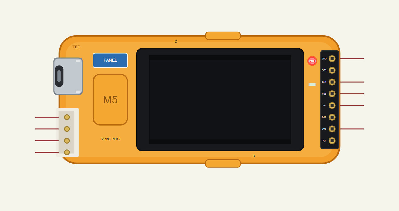
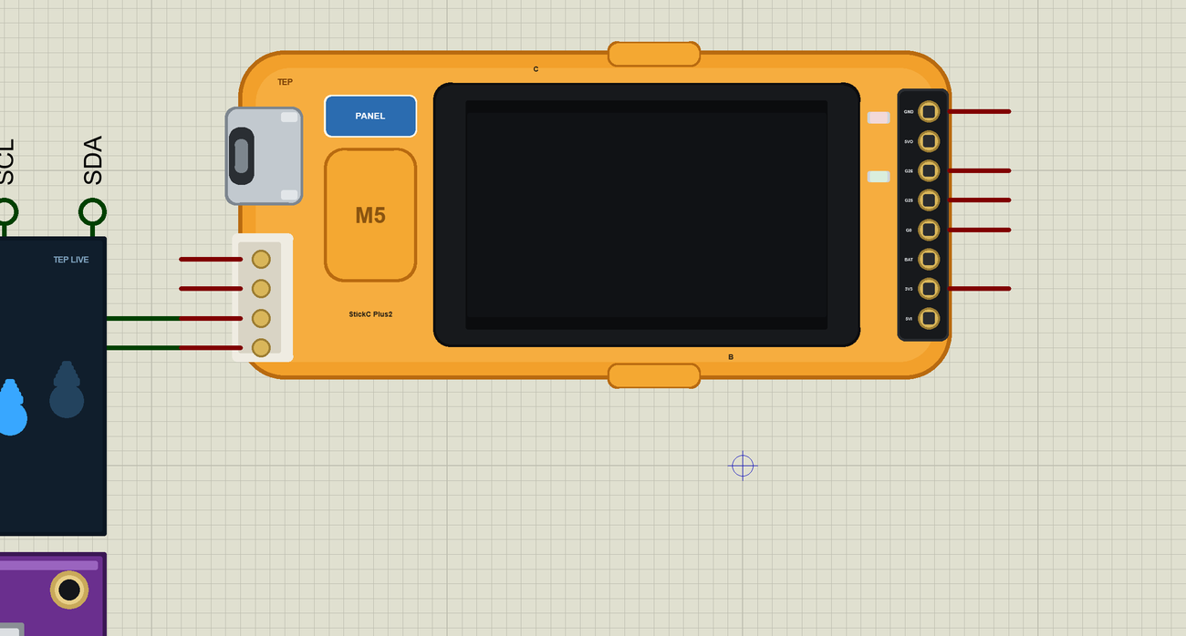
Search M5STICKC in Pick Devices; the device is in TEPSTICKCP2.LIB (Microprocessor ICs, ESP32 Boards), with the prefix U. The stick lies on its side, because that is how setRotation(1) stands upright. It has two windows: click the USB-C port for the serial monitor, and the PANEL pad or the display for the panel. We drew it larger than life, so that you can read the display on the sheet.
The Pins
| Socket | Pins | What the library does with them |
|---|---|---|
| Grove | G32, G33 | Wire SDA and SCL, or GPIO |
| Grove | 5V, GND | the supply |
| HAT | G26, G25, G0 | GPIO, PWM, interrupt |
| HAT | 3V3, GND | the supply |
| Inside | 37, 39, 35 | keys A, B and C, LOW when pressed |
| Inside | 19, 2, 4 | the red LED, the buzzer, HOLD |
The variant gives the inside pins names, such as BUTTON_A, LED_RED, BUZZER_PIN, POWER_HOLD and TFT_CS, so a sketch reads clearly. On a real Plus2 G25 shares its pin with G36. The 5VO, BAT and 5VI contacts of the HAT socket are drawn only. Note that M5Stack's own M5Unified libraries are not for this part: use the pins directly, as our demo does.
Download M5StickC PLUS2 Library for Proteus
Click the button below to download M5StickC-PLUS2-Library-for-Proteus-v1.0.zip (about 3.7 MB, without the source code of the models):
M5StickC PLUS2 Library for Proteus V1.0- README.txt: installation, the demo, the pins, the properties, troubleshooting and the limits.
- Proteus Library Files:
TEPSTICKCP2.LIBand the demo's parts:TEPSHT31.LIB,TEPMOBILE.LIBandTEPLAPTOP.LIB. - Proteus Model Files:
TEPNET.DLLandTEPSHT31.DLL. - Arduino Code: the demo sketch and the TEP Boards for Proteus add-on 1.49.0.
- Proteus Simulation: the demo project, its HEX file and copies of the DLLs.
No Proteus yet? Read How to Download and Install Proteus 7 and 8. New to libraries? Follow How to Install a New Library in Proteus.
How to Install M5StickC PLUS2 Library for Proteus
- Close Proteus and extract the whole zip file, for example to your Desktop.
- Copy the files from Proteus Library Files into the LIBRARY folder of Proteus.
- Copy the DLLs from Proteus Model Files into the MODELS folder, replacing an older TEPNET.DLL.
- Delete
TEPSTICKCP2.IDXfrom the LIBRARY folder if it is there. - For your own sketches, copy Arduino Code\TEP Boards for Proteus\hardware into your Arduino sketchbook (Documents\Arduino) and restart the Arduino IDE; the board is M5StickC PLUS2 (TEP Proteus). Install Adafruit ST7735 and ST7789, Adafruit GFX and Adafruit BusIO from the Library Manager.
- Start Proteus, press P and search for M5STICKC.
Demo: a Climate Badge
Damp air is a quiet enemy. It rusts contacts in a server rack, moulds the stock in a store and rots the seedlings in a greenhouse. By the time you can smell it, the damage is done. A small badge on the wall can watch all day: it shows the numbers at a glance, shouts when they go wrong, and answers from your phone when you are in the next room.
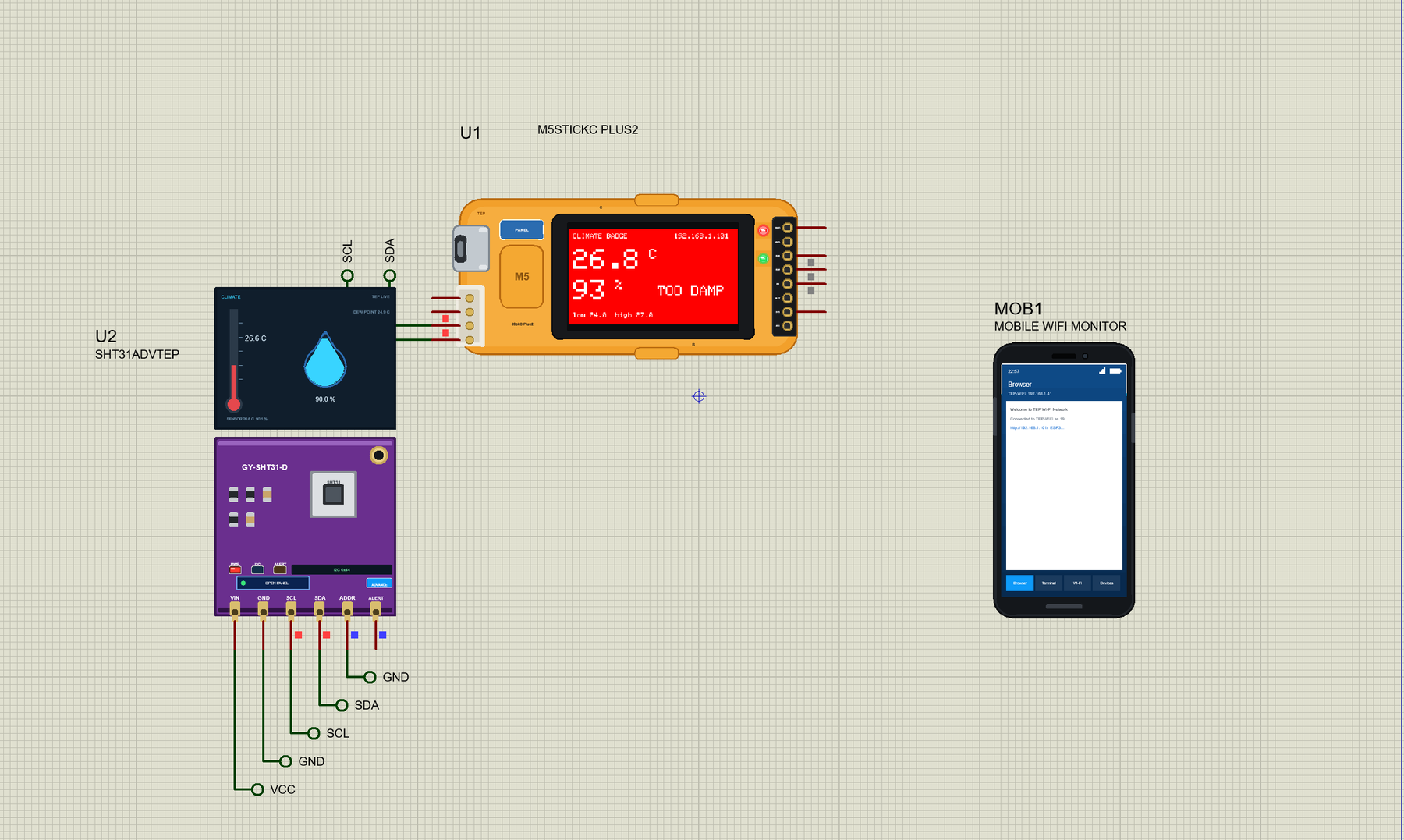
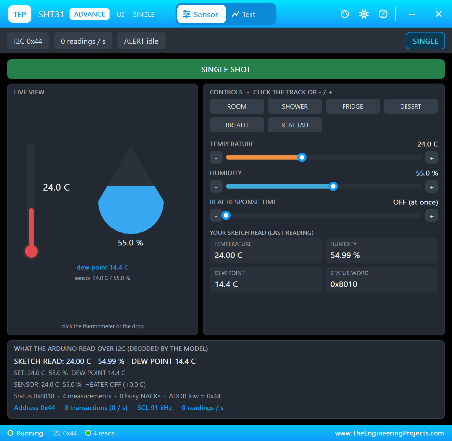
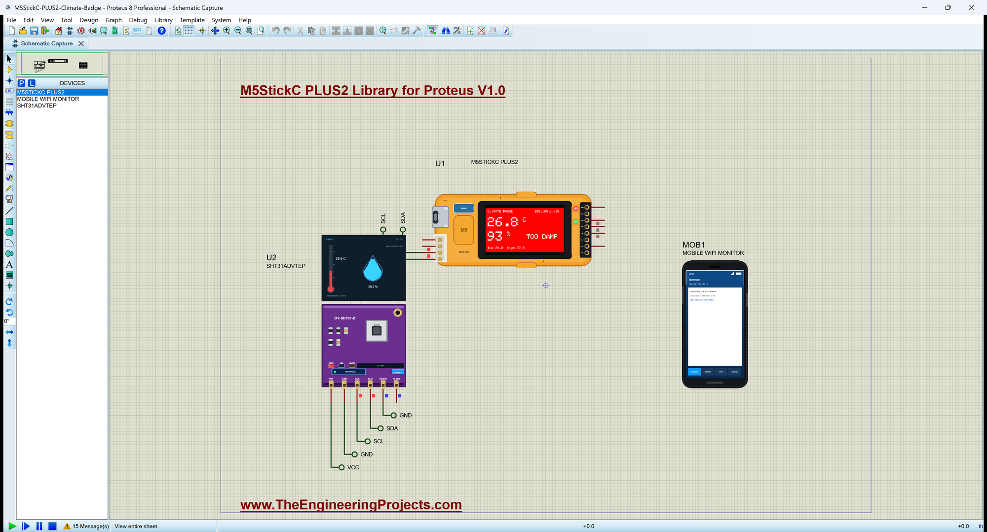
Open M5StickC-PLUS2-Climate-Badge.pdsprj. U1 runs StickC_Climate_Badge.hex. U2 is the sensor from our SHT31 Library for Proteus, in the Advance version, on the Grove socket. MOB1 is our Mobile WiFi Monitor, and the monitor is the same window as our TEP Serial Monitor Advance for Proteus.
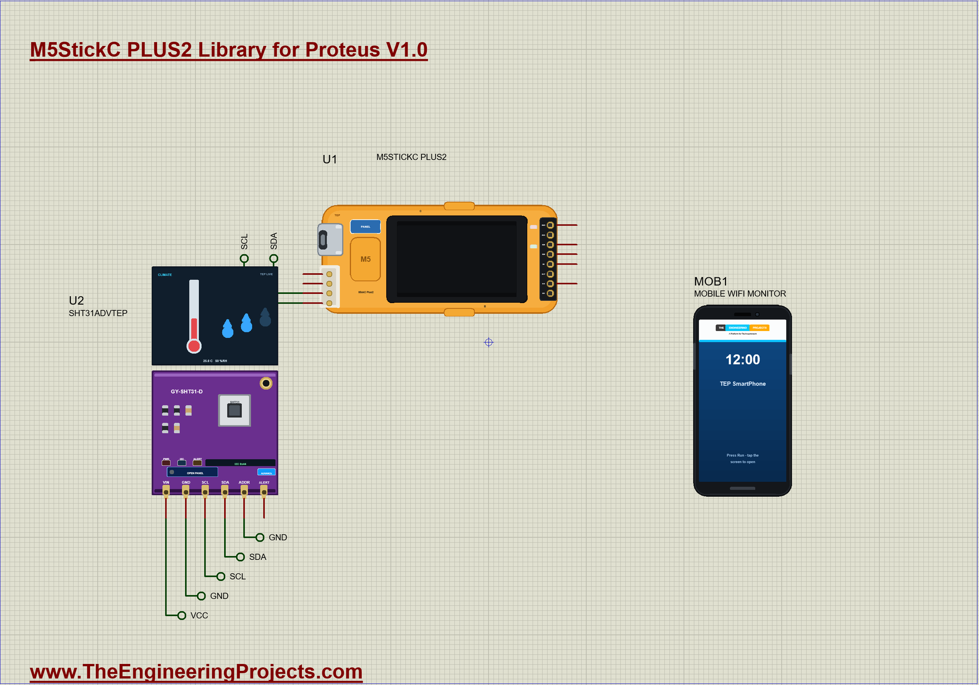
| Module pin | Net label | Stick pin | What it does |
|---|---|---|---|
| SHT31 SDA, SCL | SDA, SCL | G32, G33 | I2C, address 0x44 |
| SHT31 ADDR | GND | - | selects 0x44 |
| SHT31 VIN, GND | VCC, GND | - | the supply |
What Is Relative Humidity?
Warm air can hold more water vapour than cold air. Relative humidity says how full the air is, as a percentage of the most it can hold at that temperature. That is why a cold room can feel clammy at the same amount of water that feels dry in a warm one. Mould usually needs more than about 70 % for a long stretch, so that is the limit in our sketch. The dew point, shown on the SHT31's window, is the temperature at which the air would start to leave water on a surface. When a cold pipe or a metal rack falls below it, drops form there.
Why a Grove Socket Is Handy
Grove is a small keyed plug with four wires: ground, power and two signals. It only fits one way round, so you cannot swap the power by accident, and it needs no soldering. On the StickC the two signals are G32 and G33, and Wire.begin(32, 33) turns them into an I2C bus. Any Grove sensor with the same address plan can share it.
We could have used a library, but the SHT31 is so simple that a few lines of Wire show exactly how it works. Send two command bytes, wait for the measurement, then read six bytes: the temperature, a check byte, the humidity and a second check byte. The check byte is a CRC, and it catches a corrupted reading on a long cable. The two formulas come straight from the Sensirion datasheet:
bool readSensor() {
  Wire.beginTransmission(SHT31);
  Wire.write(0x24); Wire.write(0x00);                       // a single measurement, high repeatability
  if (Wire.endTransmission() != 0) return false;
  delay(20);
  if (Wire.requestFrom((int)SHT31, 6) != 6) return false;
  byte d[6];
  for (byte i = 0; i < 6; i++) d[i] = Wire.read();
  if (crc8(d, 2) != d[2] || crc8(d + 3, 2) != d[5]) return false;
  const long rawT = ((long)d[0] << 8) | d[1], rawH = ((long)d[3] << 8) | d[4];
  tempC = -45 + 175.0 * rawT / 65535.0;
  humidity = 100.0 * rawH / 65535.0;
  return true;
}
The Check Byte
A CRC is a kind of fingerprint of the data. The sensor works it out from the two data bytes and sends it along, and the sketch works it out again and compares. If one bit flips on the way, the two no longer match, so the reading is thrown away instead of setting off a false alarm. The polynomial 0x31 and the start value 0xFF are the ones in the datasheet:
byte crc8(const byte *d, byte n) {                          // the SHT31's check byte
  byte c = 0xFF;
  for (byte i = 0; i < n; i++) { c ^= d[i]; for (byte b = 0; b < 8; b++) c = c & 0x80 ? (c << 1) ^ 0x31 : c << 1; }
  return c;
}
Starting the Display
The display shares nothing with the Grove socket: it has its own SPI bus inside the case. tft.init(135, 240) tells Adafruit's library the size, including the offsets of this small glass inside the larger memory of the ST7789, and setRotation(1) turns it on its side. The backlight is a plain pin, so a real sketch can dim it with PWM. Note the first line in setup(): HOLD keeps a real Plus2 switched on.
void setup() {
  Serial.begin(115200);
  Serial.println(F("StickC Climate Badge - The Engineering Projects"));
  pinMode(POWER_HOLD, OUTPUT); digitalWrite(POWER_HOLD, HIGH);   // HOLD: the PLUS2 stays on after the power key is released
  pinMode(BUTTON_A, INPUT);
  pinMode(LED_RED, OUTPUT); digitalWrite(LED_RED, LOW);
  pinMode(TFT_BL, OUTPUT); digitalWrite(TFT_BL, HIGH);
  SPI.begin(TFT_SCLK, -1, TFT_MOSI, TFT_CS);
  tft.init(135, 240);
  tft.setRotation(1);
  tft.fillScreen(ST77XX_BLACK);
  tft.setTextColor(ST77XX_WHITE); tft.setTextSize(2); tft.setCursor(6, 50); tft.print(F("Climate Badge"));
  Wire.begin(GROVE_SDA, GROVE_SCL);
  WiFi.begin(WIFI_NAME, WIFI_PASS);
  while (WiFi.status() != WL_CONNECTED) delay(100);
  Serial.print(F("Wi-Fi: http://")); Serial.print(WiFi.localIP()); Serial.println(F("/"));
  server.on("/", handleRoot);
  server.on("/clear", handleClear);
  server.begin();
}
Drawing the Pages
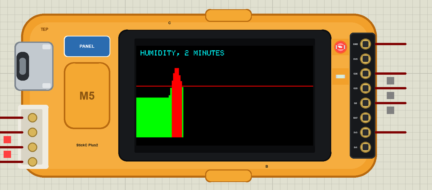
The sketch has two pages. The first shows the numbers, and turns the whole screen red when the air is too damp. A red screen is easy to see from across a room, which is what a warning needs. The second page is a graph of the last two minutes, one pair of pixels per reading, with a red line at the 70 % limit. Key A swaps between them:
void pageNow() {
  tft.fillScreen(humid ? ST77XX_RED : ST77XX_BLACK);
  tft.setTextColor(ST77XX_WHITE);
  tft.setTextSize(1); tft.setCursor(6, 6); tft.print(F("CLIMATE BADGE"));
  tft.setCursor(150, 6); tft.print(WiFi.localIP());
  tft.setTextSize(4); tft.setCursor(6, 28); tft.print(tempC, 1); tft.setTextSize(2); tft.print(F(" C"));
  tft.setTextSize(4); tft.setCursor(6, 72); tft.print(humidity, 0); tft.setTextSize(2); tft.print(F(" %"));
  tft.setTextSize(1); tft.setCursor(6, 118);
  tft.print(F("low ")); tft.print(lowC, 1); tft.print(F("  high ")); tft.print(highC, 1);
  if (humid) { tft.setTextSize(2); tft.setCursor(126, 80); tft.print(F("TOO DAMP")); }
}
The Alarm
The sketch only acts when the state changes. Without that test, it would print a warning and sound the buzzer every two seconds for as long as the air stays damp, which is a good way to get a badge thrown in a drawer. The screen gets the same care: it is redrawn only when a number has changed, so it does not flicker. While the alarm stands, a small timer blinks the red LED:
void update() {
  if (millis() < nextRead) return;
  nextRead = millis() + 2000;
  if (!readSensor()) { Serial.println(F("SHT31 not answering")); return; }
  if (tempC < lowC) lowC = tempC;
  if (tempC > highC) highC = tempC;
  const bool now = humidity > HUMID_LIMIT;
  if (now != humid) {
    humid = now;
    Serial.print(humid ? F(">> TOO DAMP: ") : F(">> Dry again: ")); Serial.print(humidity, 0); Serial.println(F(" %"));
    if (humid) tone(BUZZER_PIN, 2000, 300);
    else digitalWrite(LED_RED, LOW);
    shownH = -100;                                          // the screen's colour changes: draw it
  }
  if (millis() >= nextGraph) {
    nextGraph = millis() + 2000;
    if (used == GRAPH_W) { memmove(history, history + 1, GRAPH_W - 1); used--; }
    history[used++] = (byte)humidity;
  }
  if (page == 1 || fabs(tempC - shownC) >= 0.05 || fabs(humidity - shownH) >= 0.5) {   // only when a number has changed: no flicker
    shownC = tempC; shownH = humidity;
    draw();
  }
}
The Page for the Phone
A very small web page is enough. WebServer calls a function for each address, and that function builds the page as a String. The link to /clear starts the lowest and highest values again from the present reading. A page like this needs no app on the phone, and any browser on the same Wi-Fi can read it:
void handleRoot() {
  String h = F("<html><body><h2>Climate Badge</h2><p>");
  h += String(tempC, 1) + F(" C, ") + String(humidity, 0) + F(" %</p><p>Low ") + String(lowC, 1) + F(", high ") + String(highC, 1) + F("</p>");
  if (humid) h += F("<p><b>TOO DAMP</b></p>");
  h += F("<p><a href='/clear'>CLEAR</a></p></body></html>");
  server.send(200, "text/html", h);
}
Keeping the Loop Quick
Five small jobs share loop(): the web server, the key, the sensor, the LED and the log. Each one checks its own clock with millis() and returns at once when it has nothing to do. server.handleClient() must run often, or the phone waits. The only pause is the 20 ms that the SHT31 needs for a measurement, once every two seconds, and that is short enough that nobody will notice it on the page or at the key.
Run the Demo
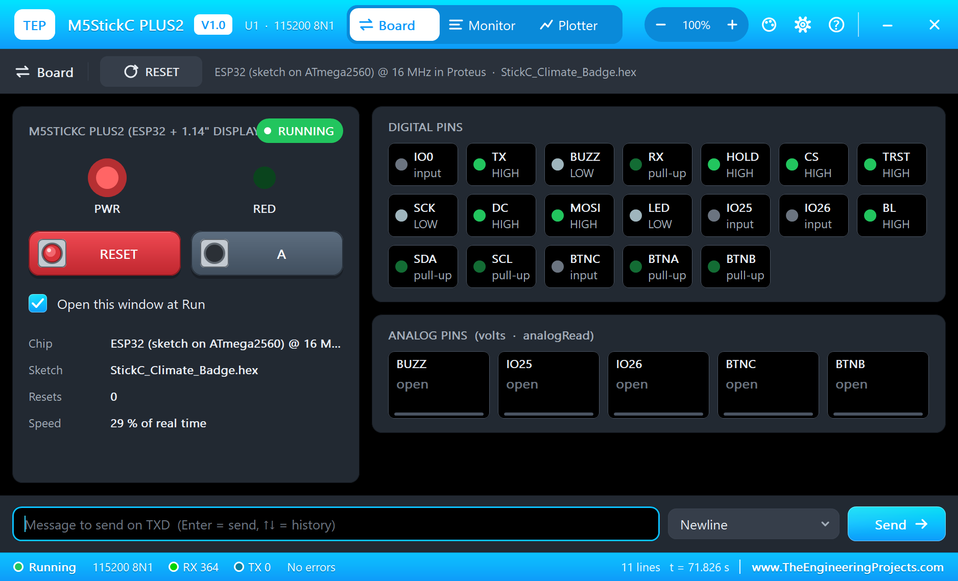
Press Run. The stick joins the Wi-Fi network and starts reading the sensor. The monitor prints a status line every ten seconds:
StickC Climate Badge - The Engineering Projects
Wi-Fi: http://192.168.1.101/
24.0 C  55 %  low 24.0  high 24.0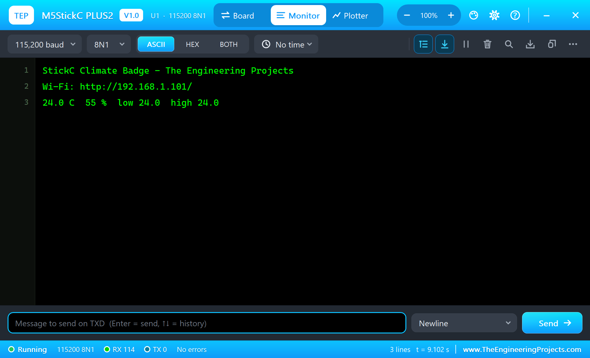
Too Damp
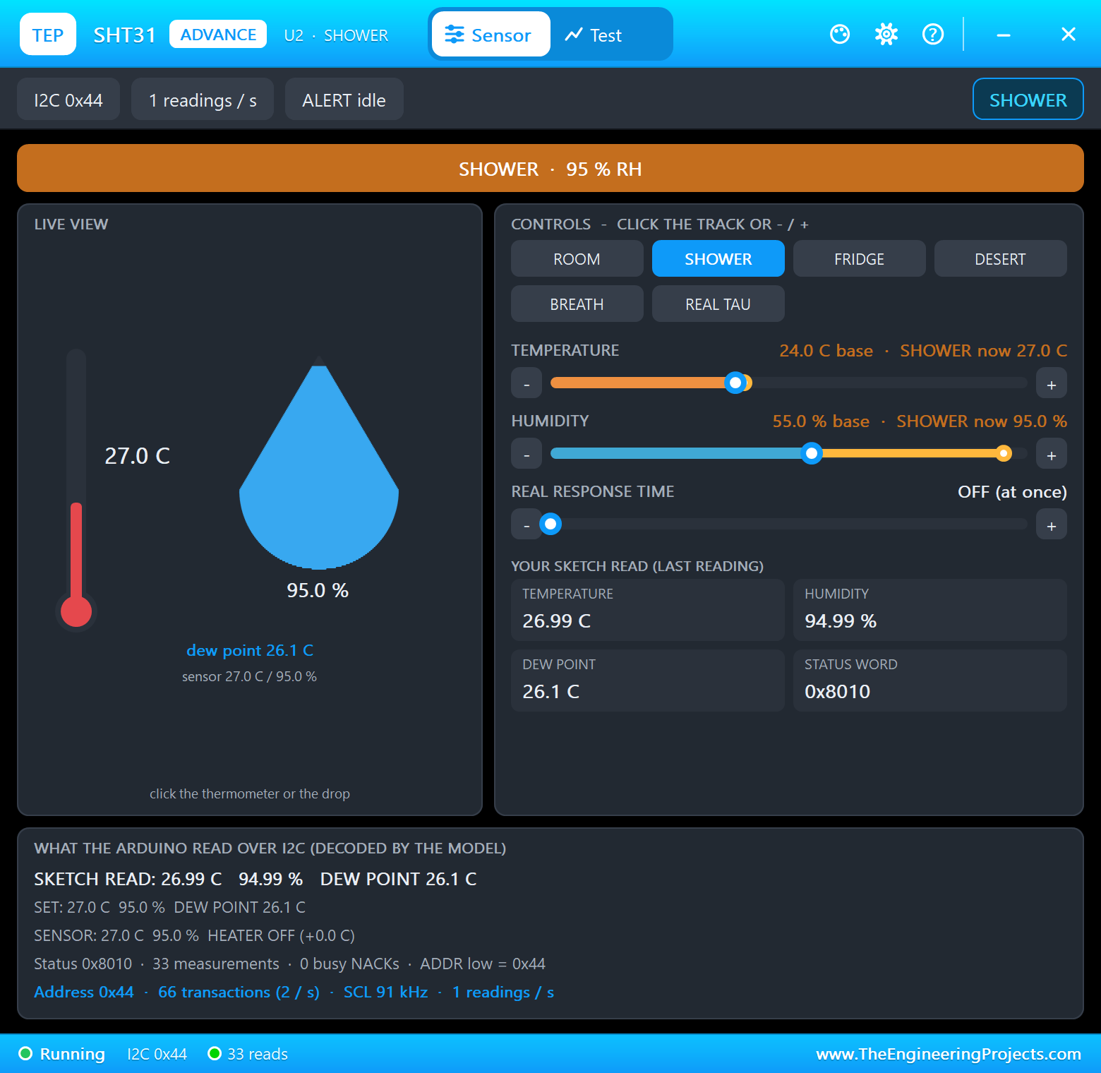
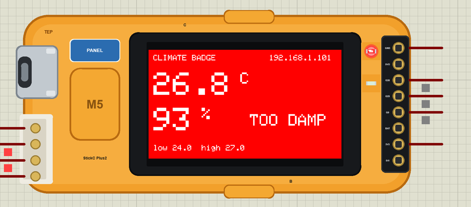
Click SHOWER on the SHT31's window. The humidity climbs, and as it passes 70 % the screen turns red, the red LED starts to blink and the buzzer pin sounds:
The Graph
Press the M5 key, or the BOOT key on the monitor's Board tab. The screen shows the last two minutes of humidity, in green below the limit and in red above it:
The Phone
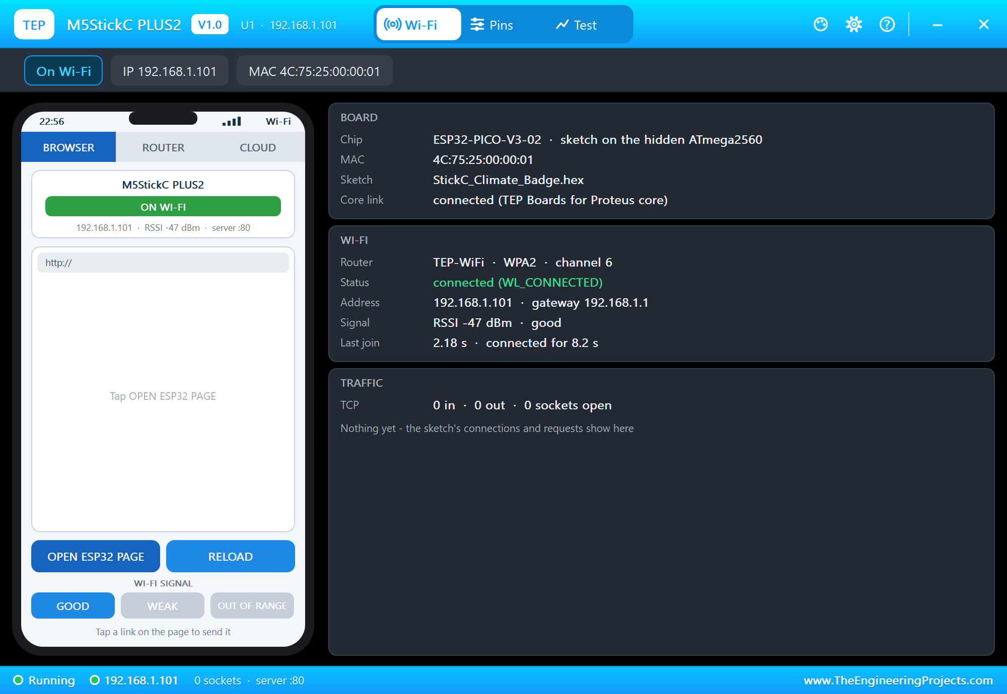
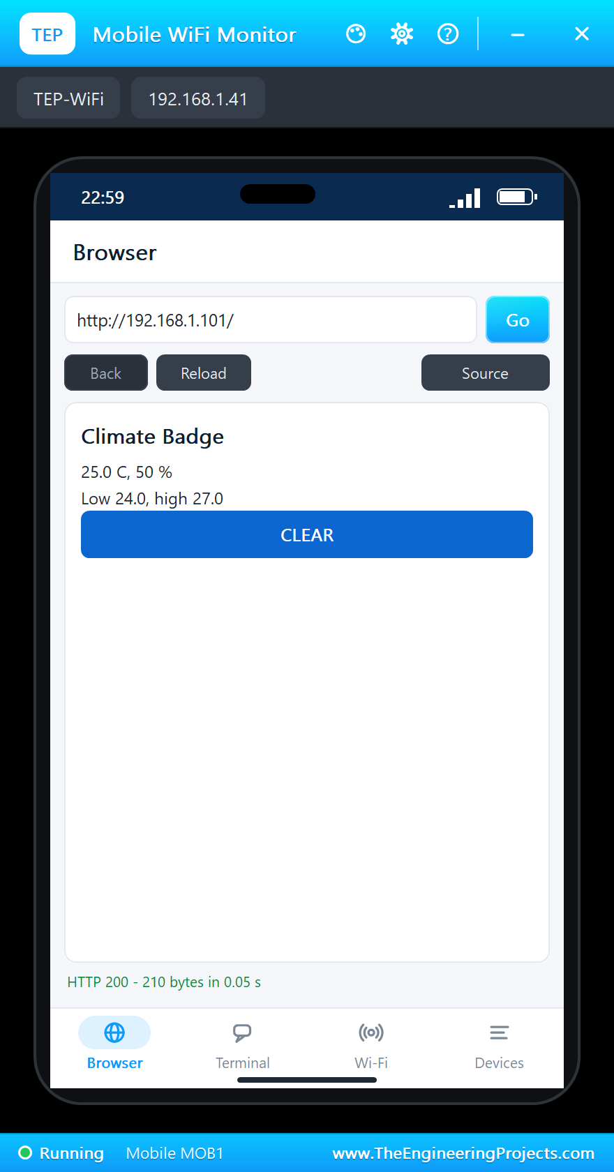
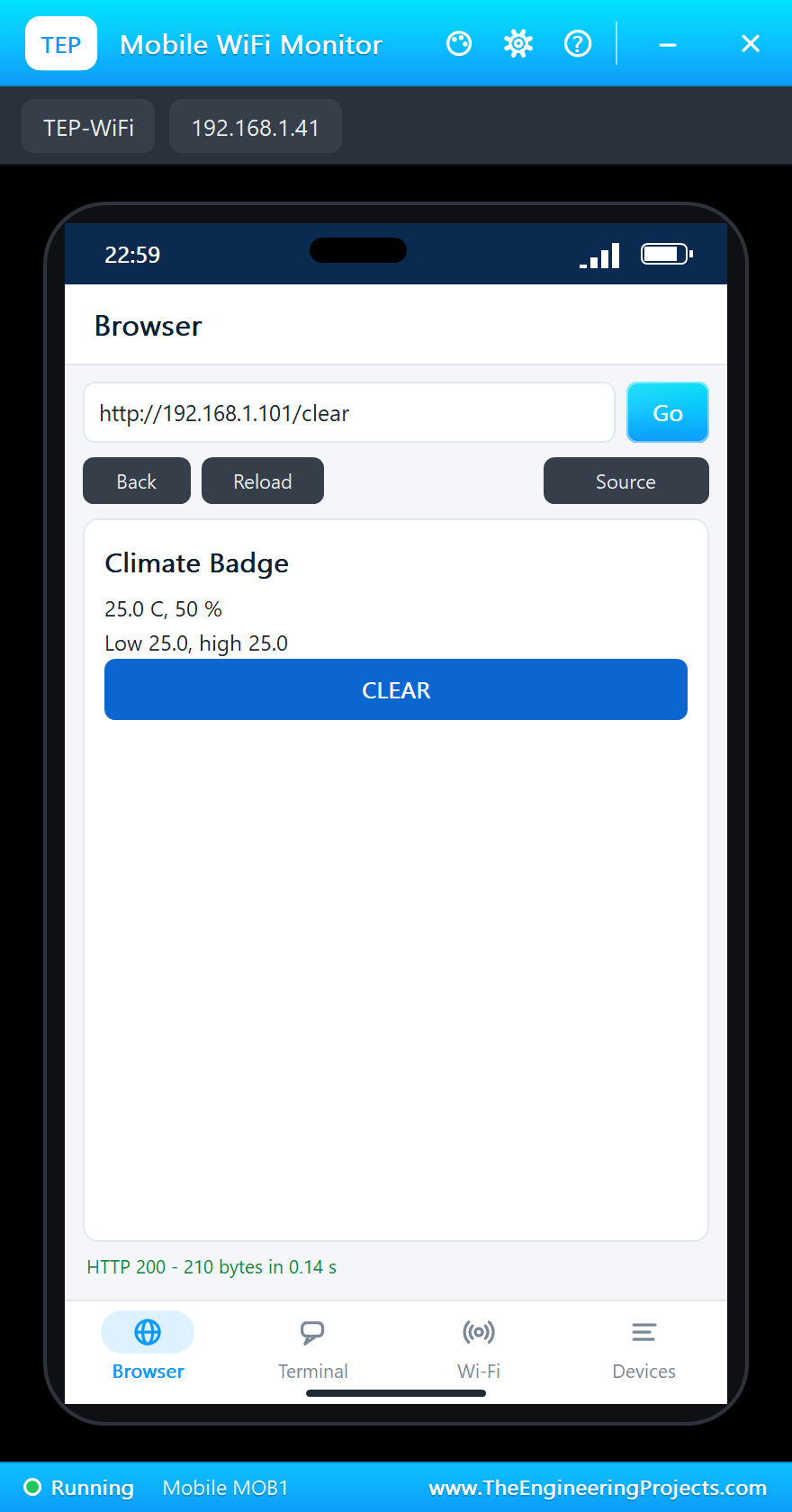
Click ROOM on the SHT31's window, and the alarm clears. Now click ESP32 U1 on the phone. The page shows the numbers and the lowest and highest temperature so far. Tap CLEAR to start them again:
The built-in serial monitor has followed everything:
24.0 C  55 %  low 24.0  high 24.0
>> TOO DAMP: 78 %
27.0 C  95 %  low 24.0  high 27.0
>> Key A: the graph
25.6 C  77 %  low 24.0  high 27.0
>> Dry again: 69 %
25.0 C  50 %  low 24.0  high 27.0
>> Low and high cleared from the phone
25.0 C  50 %  low 25.0  high 25.0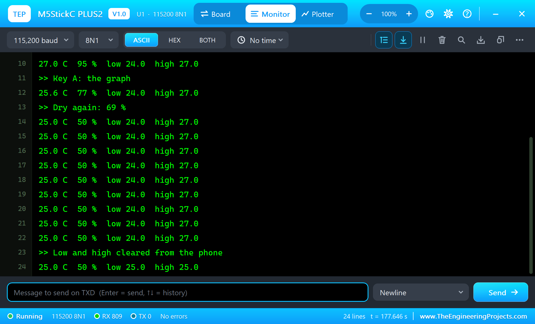
Try It Yourself
- Click FRIDGE or DESERT on the SHT31 and watch the low and high follow.
- Change
HUMID_LIMITand rebuild the sketch. - Add the temperature to the graph in a second colour.
- Use key B on GPIO39 to dim the backlight with
analogWrite(TFT_BL, 80).
Ideas to Extend the Badge
- Send a message to a chat app or a web service when the alarm starts.
- Keep a day of readings, one every ten minutes, and show them on the page.
- Add a limit for the temperature too, for a server room.
- Put two badges in two rooms and let the phone read both.
Your Own Sketches
Write the sketch in the Arduino IDE with the board M5StickC PLUS2 (TEP Proteus), use Sketch > Export Compiled Binary and set the part's PROGRAM property to the .hex. The pin names are in the variant, so your sketch stays short. On a real stick use the same pins with Espressif's "esp32" package.
Things to Know Before Using a Real StickC Plus2
- Set HOLD first: a real Plus2 turns off when you release the power key unless the sketch sets GPIO4 HIGH.
- The Grove I2C pins: call
Wire.begin(32, 33). The inside bus on GPIO21 and 22 belongs to the motion sensor and the clock. - G25 and G36 share a pin: set the unused one to input, or they will fight.
- The battery is tiny: 200 mAh will not last a day with Wi-Fi and the backlight on, so use USB power for a wall badge, or sleep between readings.
- The case warms up: a sensor on a short Grove lead reads high, so keep the SHT31 away from the stick.
Properties of the M5StickC PLUS2
| Property | What it does |
|---|---|
| PROGRAM | the sketch: a .hex from TEP Boards for Proteus (board "M5StickC PLUS2") |
| WIFISSID, WIFIPASS | the router in range (TEP-WiFi, 12345678) |
| MONITOR, BAUD, AUTOOPEN | the built-in serial monitor: on, its baud rate (115200), open at Run |
Troubleshooting
- The display stays black: set
TFT_BLHIGH, thenSPI.begin()andtft.init(135, 240). - The picture is sideways: use
tft.setRotation(1). - The SHT31 does not answer: call
Wire.begin(GROVE_SDA, GROVE_SCL); the address is 0x44 with ADDR LOW. - The phone shows the Welcome page: click ESP32 U1 in its list of devices.
- A number goes wrong above 32767: int is 16 bits in the simulation - use long.
Limitations of the Simulation
- Your sketch gets 8 KB of RAM in the simulation, and there are no FreeRTOS tasks and no second core.
- The MPU6886, the BM8563, the microphone, IR light, the battery, and sound from the buzzer are not modelled. Bluetooth is not modelled.
- M5Unified and the M5StickCPlus2 library do not run on this part: use the pins directly.
- M5StickC PLUS2 is a name of M5Stack and ESP32 of Espressif Systems; this library is not made or endorsed by them or by Labcenter.
- Tested in Proteus 8.5 in October 2026 (the demo as shipped, about 180 s of simulation). Proteus 7 is not supported.
So, that was all about the M5StickC PLUS2 Library for Proteus. I hope it helps you try your ideas for this lovely little stick before you buy one - the display, the keys, the Grove socket and Wi-Fi in one simulation. If you have any questions, ask in the comments and I will help you out. Till the next tutorial, take care and have fun!