Hello friends, I hope you all are doing great. Today, I am going to share the new Trimmer Potentiometer Library for Proteus. A trimmer, or trimpot, is the small cousin of the potentiometer. It has no knob and no shaft for your fingers; you turn it with a small screwdriver, once, while you calibrate the circuit, and then you leave it alone. Look closely at almost any module on your bench, and you will find one: it sets the contrast of an LCD, the threshold of a sensor board, or the output of a power supply.
Trimmer Potentiometer Library for Proteus
Latest version: V1.0 (November 2026, this tutorial)
Other component libraries: C945 Transistor · PC817 Optocoupler · Relay Module · Resistor · 5 mm LED · Designer Colour LED · Push Button · Active Buzzer · Electrolytic Capacitor · Ceramic Capacitor · Tantalum Capacitor · Film Capacitor · 1N4007 Diode · Zener Diode · Schottky Diode · Supercapacitor · Photodiode · RGB LED · Bridge Rectifier · Flashing LED · Bi-Colour LED · SMD LED · Slide Switch · Toggle Switch · Rocker Switch · Micro Limit Switch · Emergency Stop Switch · SMD Resistor · Power Resistor · Resistor Network · Potentiometer · Slide Potentiometer · NTC Thermistor · DIP Switch · Fuse · Passive Buzzer · Mini Speaker · 7-Segment Display · LED Bar Graph · IR / UV LED · Small Transistors · TIP122 Darlington · N-MOSFET · P-MOSFET · PC817 Optocoupler · Filament Bulb · Power LED · Voltage Regulator · SCR and TRIAC · Inductor · Toroid Inductor · Crystal
Helping Tools
- Serial Monitor Advance: a serial terminal window for the UART of your board
- Serial Monitor Expert: the serial monitor with extra debugging tools
- LCD Library for Proteus V3.0: 16x2, 20x4 and I2C LCDs to show your readings
Our library has the two trimmers you will meet most often, at true scale: the blue 3296 box with its brass screw, which takes 25 turns from one end to the other, and the small square 3362, which turns through 240 degrees. At Run, you turn them with a click, just like a screwdriver, and the setting stays after Stop. The demo is the most classic trimmer job of all: the contrast of a 16x2 character LCD. Turn it wrong, and the text fades away; turn it right, and it is crisp.
NOTICE: Our team has put a lot of effort into these small parts: the bodies, the animation and the pop-ups are all our own design, and you get them free. Your feedback is the fuel that keeps us going, so please tell us what you think in the comments below or in the Trimmer Potentiometer board of our forum. And if our free libraries help you, you can buy us a coffee. So, let's get started with the Trimmer Potentiometer Library for Proteus:
What is a Trimmer Potentiometer?
A trimmer potentiometer is a potentiometer made to be set once. Inside, it is exactly like the knobs in our Potentiometer Library for Proteus: a resistive track between pins 1 and 3, and a wiper, pin 2, that slides along it. The difference is in the use. A potentiometer is a control that someone turns every day. A trimmer is an adjustment that the maker sets during calibration and then forgets. That is why it is small, why it sits flat on the board, and why it has a screwdriver slot instead of a shaft.
Most trimmers today use a cermet track, a mix of ceramic and metal, which is stable with temperature and time. Both of our trimmers are cermet parts rated at 0.5 W for the whole track, with a tolerance of about 10 %. A trimmer is also built for a short working life: a few hundred adjustments, not the many thousands of turns a panel pot takes. Turn it as often as you like in the simulation, but on a real board, treat it as a setting, not a control.
| Feature | The 3296 | The 3362 |
|---|---|---|
| Style | Bourns 3296W, top adjust | Bourns 3362P, top adjust |
| Size | 9.53 x 4.83 mm, a blue box | 1/4 inch square, blue |
| Travel | 25 turns of a brass screw | 240 degrees of a cream rotor |
| Rating | 0.5 W, cermet | 0.5 W, cermet |
| Pins | three in a line, 2.54 mm apart | three in a line, 2.54 mm apart |
Single Turn or Multi-Turn
The 3362 is a single-turn trimmer: its whole track lies within 240 degrees of its rotor, much like a tiny potentiometer. It is quick to set, but every degree moves the wiper about 0.4 % of the track. The 3296 is a multi-turn trimmer: its screw is a lead screw that walks the wiper slowly along a straight track, 25 turns from end to end. One full turn moves the wiper only 4 %, so you can set a voltage to a few millivolts. At either end, a small slip clutch lets the screw keep turning without harm, so a 3296 never breaks at its stop, but it also never tells you that you have reached it.
Reading the Markings
Trimmers print their value as a three-digit code, the same code as an SMD resistor: two digits and then the number of zeros. So 103 is 10k, 502 is 5k and 104 is 100k. Values come in a short 1-2-5 series: 1k, 2k, 5k, 10k, 20k, 50k, 100k and so on. A 3296 also carries its part number, 3296W, on top, where the W means the screw sits on the top face.
Where They Are Used
Trimmers appear wherever a circuit needs one small correction that the parts themselves cannot guarantee. They set the contrast of character LCDs, the threshold of comparator boards such as the sound, light and soil moisture modules, the output voltage of adjustable regulators, the gain or offset of amplifiers, and the calibration of sensors and meters. They also make it easy to fine-tune a prototype before you swap them for fixed resistors.
The Contrast of a Character LCD
The 16x2 LCD module has a pin called V0, which sets the drive voltage of the liquid crystal and so the darkness of the characters. The usual wiring is a 10k trimmer as a divider: one end to ground, one to 5 V, and the wiper to V0. The lower V0 is, the darker the dots. Near 2.5 V the text is faint, above about 3 V it disappears completely, and near 0 V even the empty dots darken into a grid of grey blocks. Somewhere around 0.4 to 1.2 V, it is perfect. A brand new trimmer usually sits in the middle of its travel, which is exactly why a freshly wired LCD so often looks blank.
Divider or Variable Resistor
Like any pot, a trimmer can be a voltage divider, with all three pins in use, or a variable resistor, with pin 3 left free. As a variable resistor, only part of the track carries the current, and that part may take only its share of the 0.5 W rating. Our model checks this all the time and warns you before the track burns through.
Features of the Trimmer Potentiometer Library for Proteus
- The real look, at true scale: the blue 3296 box with its brass screw and the square 3362 with its cream rotor, plus our small TEP signature.
- Turned by a click: the left half of the 3296's box turns its screw back one turn, the right half on one turn. A click on the 3362's rotor points it at the mouse.
- True travel: 25 turns for the 3296, 240 degrees for the 3362, and the setting stays after Stop.
- A divider or a variable resistor: the model knows which one you wired, and says so.
- True ratings: 0.5 W for the whole track, derated for the part in use, with heating and burn-out.
- A pop-up for every trimmer: the screw with its 25 turns or the rotor on its scale, the track with both halves, eight live values, graphs, an event log and a check page.
- Chips to set it exactly: -10 %, -1 %, +1 %, +10 %, 0 %, 50 %, 100 % and a Sweep.
- A complete package: about 1.7 MB with the library, our Arduino UNO V4.0, our LCD 16x2 and the demo, without the source code of the models.
The Trimmers in Proteus
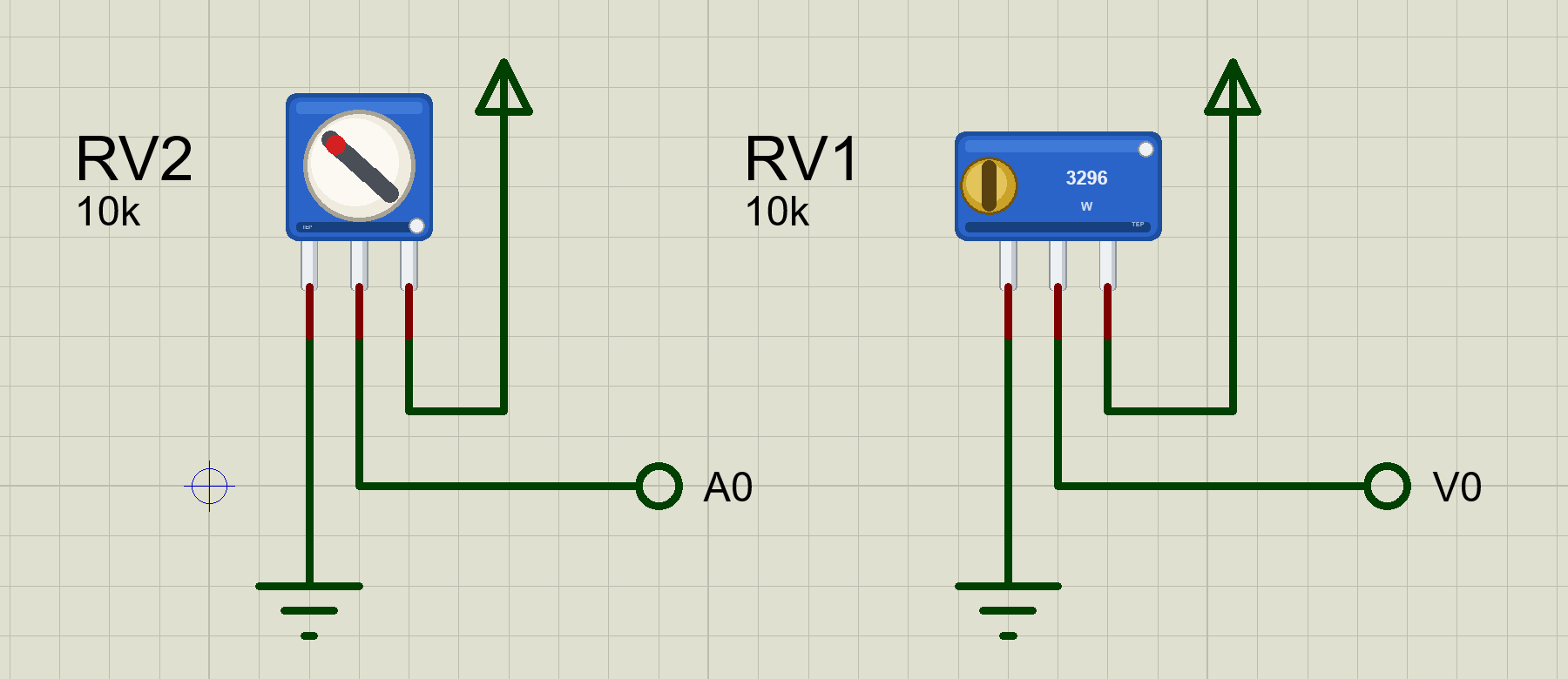
The devices are TRIMMER3296TEP and TRIMMER3362TEP in TEPTRIM.LIB, under Resistors, Variable, with the prefix RV and the model TEPTRIM.DLL. Search TRIMMER in Pick Devices. Both have their three pins in a line, 1, W and 3, on the 2.54 mm pitch, so they sit straight on a breadboard.
The Properties
| Property | What it does |
|---|---|
| Resistance (VALUE) | 10k, 1k, 100k: the 1-2-5 values real trimmers come in |
| Power rating, W | 0.5 for the whole track |
| Wiper while stopped | 0 % to 100 % in steps of 5 %: where the wiper starts |
Download Trimmer Potentiometer Library for Proteus
Click the button below to download Trimmer-Potentiometer-Library-for-Proteus-v1.0.zip (about 1.7 MB, without the source code of the models):
Trimmer Potentiometer Library for Proteus V1.0- README.txt: installation, the demo, the properties, troubleshooting and the limits.
- Proteus Library Files:
TEPTRIM.LIB,TEPLCD16X2.LIBand ourArduinoV4TEP.LIB. - Proteus Model Files:
TEPTRIM.DLL,TEPLCD.DLLandTEPARDUINO.DLL. - Arduino Code: the demo sketch.
- Proteus Simulation: the demo project, its HEX file and copies of the DLLs.
No Proteus yet? Read How to Download and Install Proteus 7 and 8. New to libraries? Follow How to Install a New Library in Proteus.
How to Install Trimmer Potentiometer Library for Proteus
- Close Proteus and extract the whole zip file, for example to your Desktop.
- Copy the files from Proteus Library Files into the LIBRARY folder of Proteus.
- Copy the files from Proteus Model Files into the MODELS folder.
- Delete
TEPTRIM.IDXfrom the LIBRARY folder if it is there. - Start Proteus, press P and search for TRIMMER.
Demo: Setting Up the Contrast of an LCD
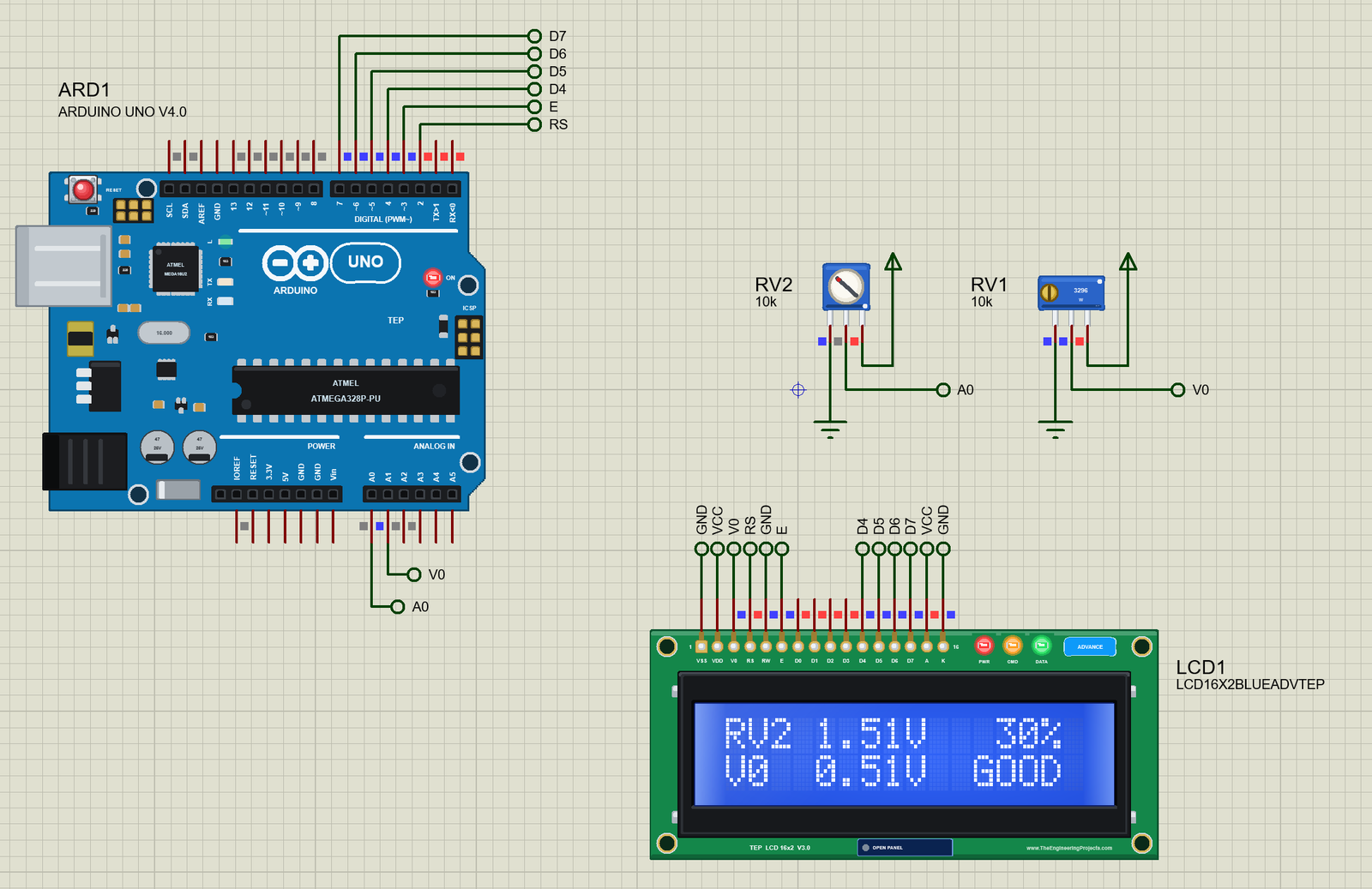
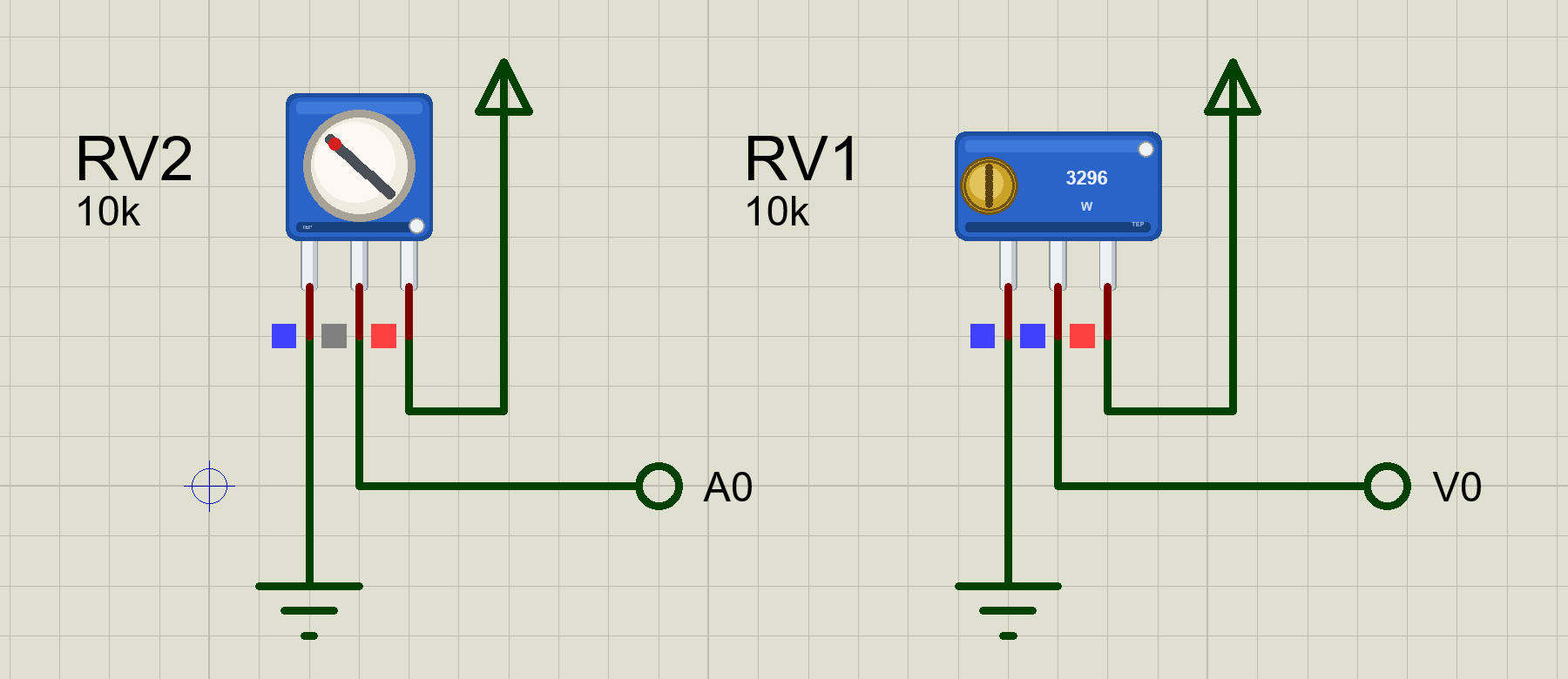
The demo wires a 16x2 LCD to the Arduino in the usual 4-bit way: RS on D2, E on D3 and the data pins D4 to D7 on D4 to D7, with RW tied to ground. RV1, the 3296, sits on the LCD's V0 pin as a divider, exactly as on a real board, and its wiper also goes to A1 so the sketch can show the voltage. RV2, the 3362, is a second divider on A0: a setting for the LCD to display. Open Trimmer-LCD-Contrast-ArduinoUnoV4.pdsprj. It runs on our Arduino UNO Library for Proteus V4.0, with its built-in monitor, the same window as our TEP Serial Monitor Advance for Proteus. The LCD is from our LCD 16x2 Library for Proteus V3.0, and its model really reads V0.
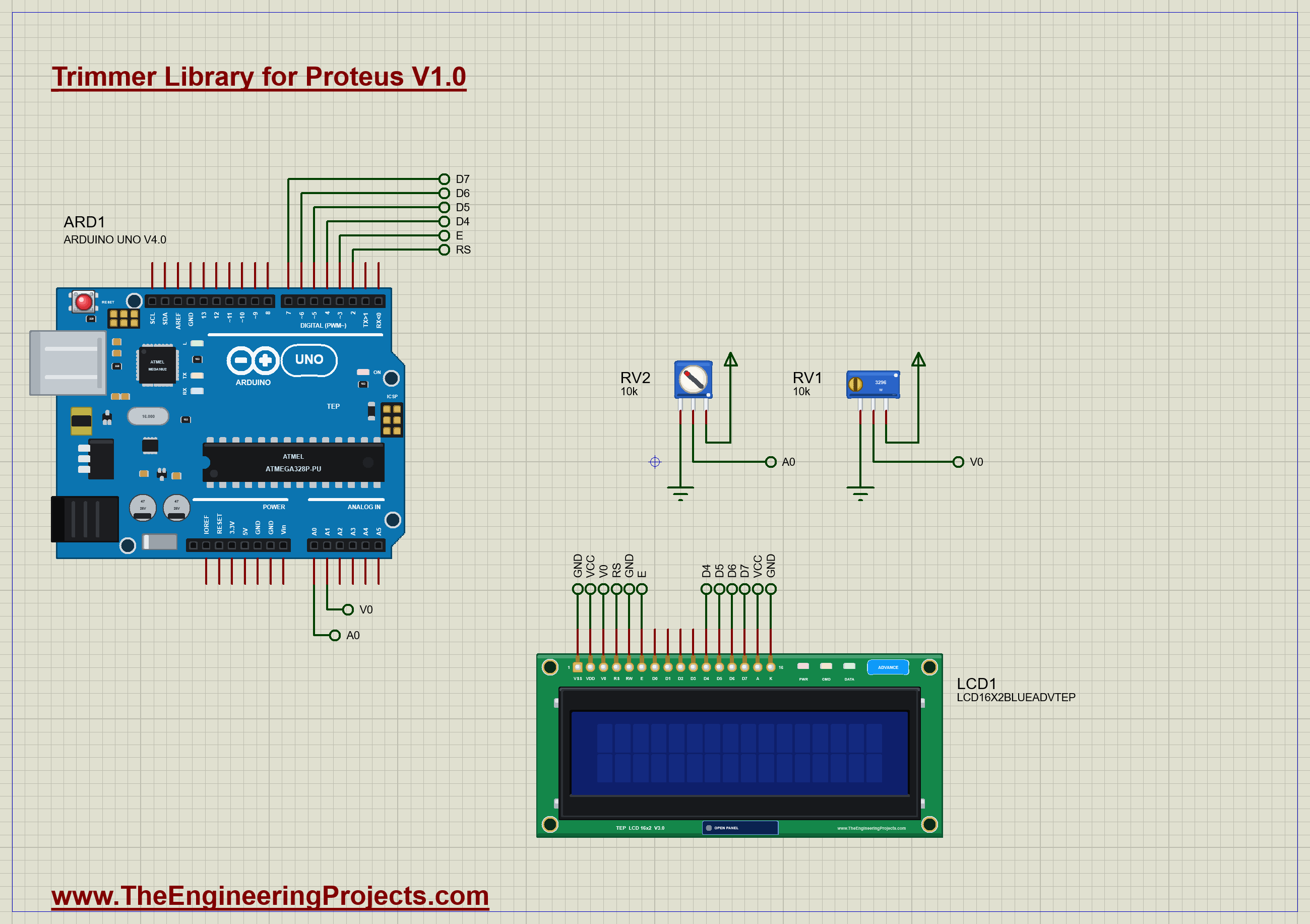
| Part | Connection | Job |
|---|---|---|
| RV1 (3296, 10k) | pin 1 GND, pin 3 +5V, wiper to V0 and A1 | the contrast, starts at 50 % |
| RV2 (3362, 10k) | pin 1 GND, pin 3 +5V, wiper to A0 | a setting to show, starts at 30 % |
| LCD1 (16x2) | RS D2, E D3, D4 .. D7, RW to GND | the display |
The Sketch
The sketch uses Arduino's LiquidCrystal library, which comes with the Arduino IDE. It reads both wipers, and turns the voltage on V0 into a word, with the same limits the LCD itself follows:
const char* contrastWord(float v0) {
  if (v0 > 3.0) return "BLANK";
  if (v0 > 1.2) return "FAINT";
  if (v0 < 0.4) return "DARK";
  return "GOOD";
}
The second line of the LCD then shows V0 and that word, so the display describes its own contrast:
  snprintf(line, sizeof line, "V0  %sV  %-5s ", b, contrastWord(v0Volts));
  lcd.setCursor(0, 1);
  lcd.print(line);
The monitor gets a line whenever a trimmer moves, at most twice a second.
Run the Demo
Press Run. RV1 starts in the middle of its travel, 12.5 turns from either end, so V0 sits at 2.47 V. The LCD is working, and the sketch is writing to it, but the text is so faint that you have to look twice. This is the most common LCD problem of all:
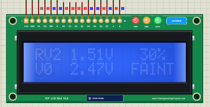
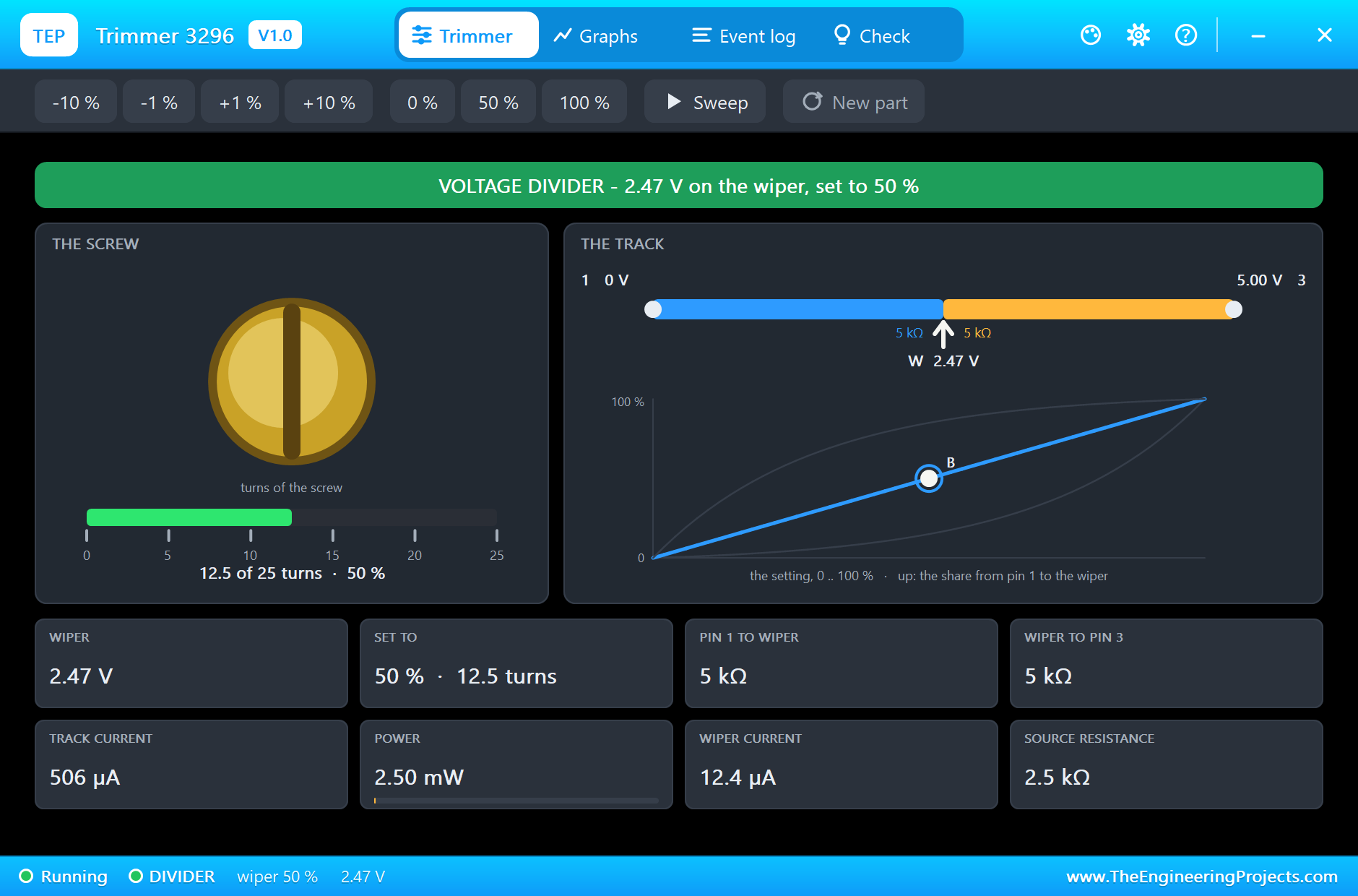
Click the small dot on RV1 to open its pop-up. The screw card shows the slot at its angle, and the ruler below it shows 12.5 of 25 turns. The track is a voltage divider with 5k on each side, and 506 µA flows through it. About 12.4 µA of that leaves through the wiper into the LCD's V0 pin:
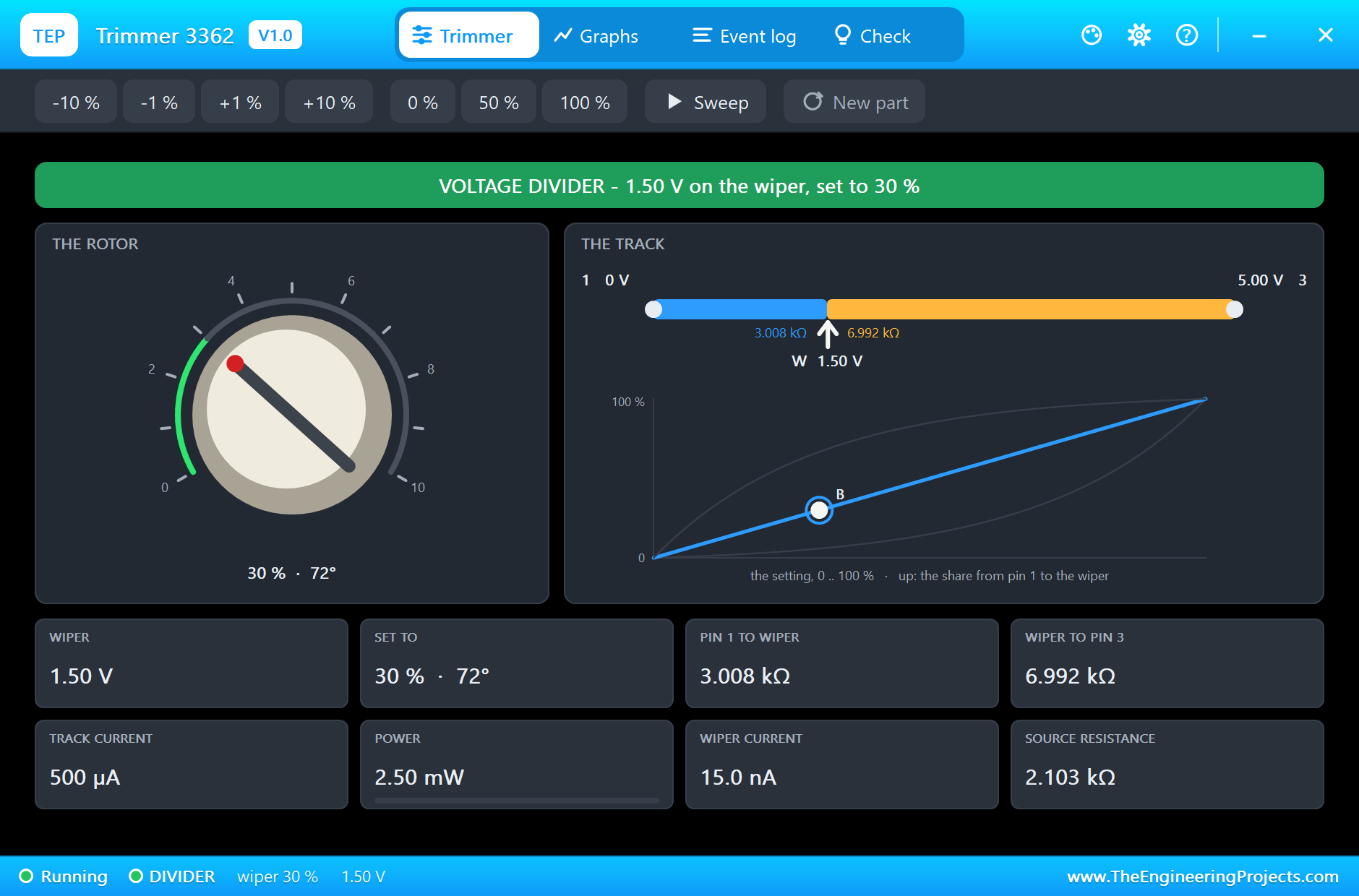
RV2's pop-up shows the single-turn trimmer instead: its rotor on a 240-degree scale, set to 30 %, with 1.50 V on its wiper:
Turning the Screw
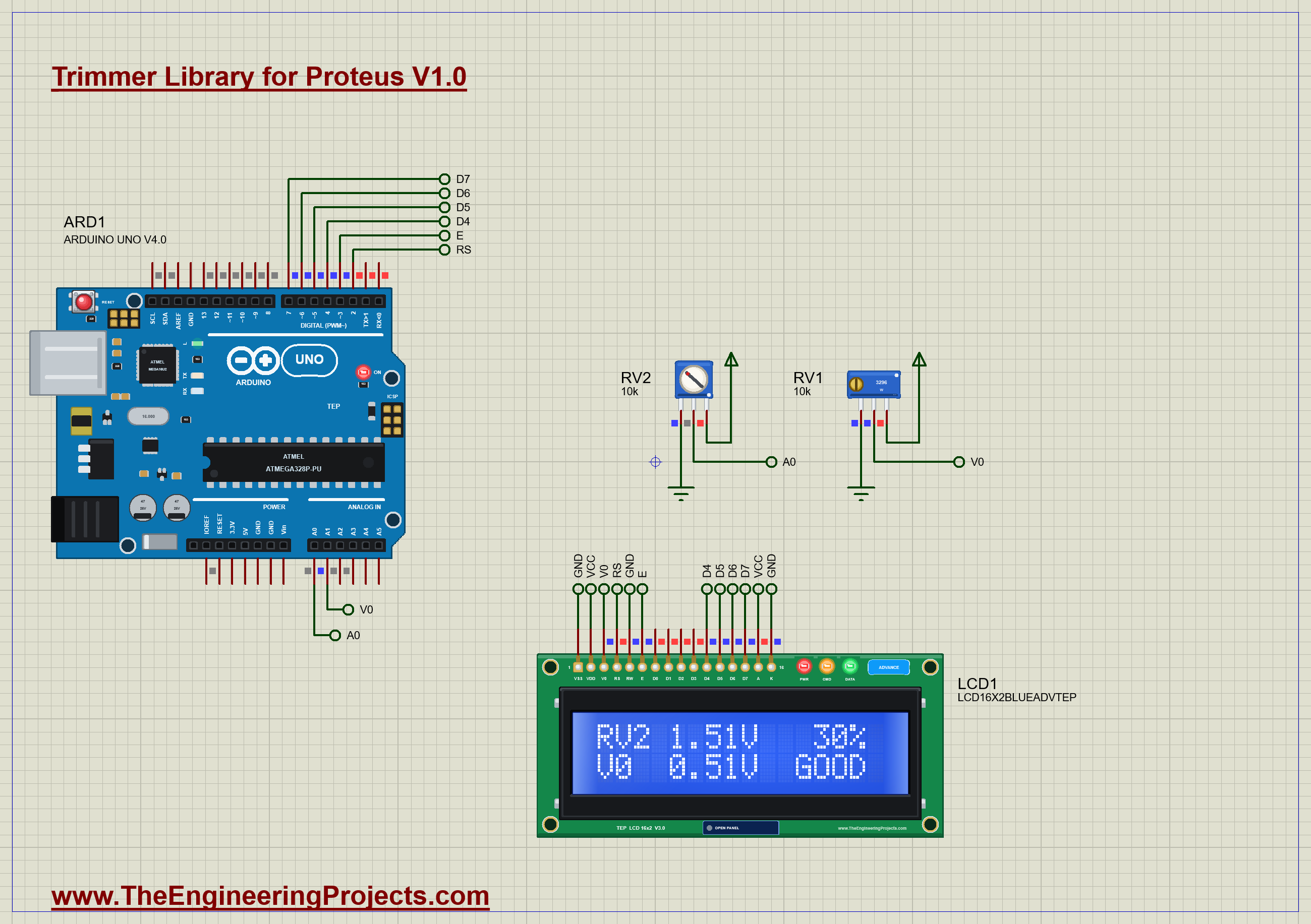
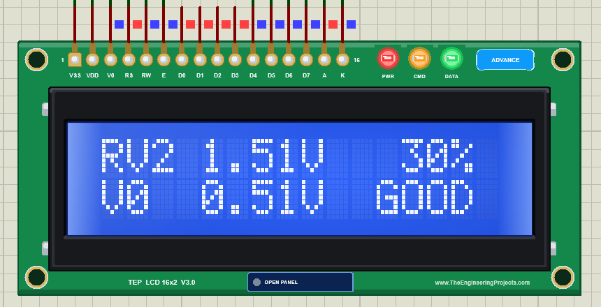
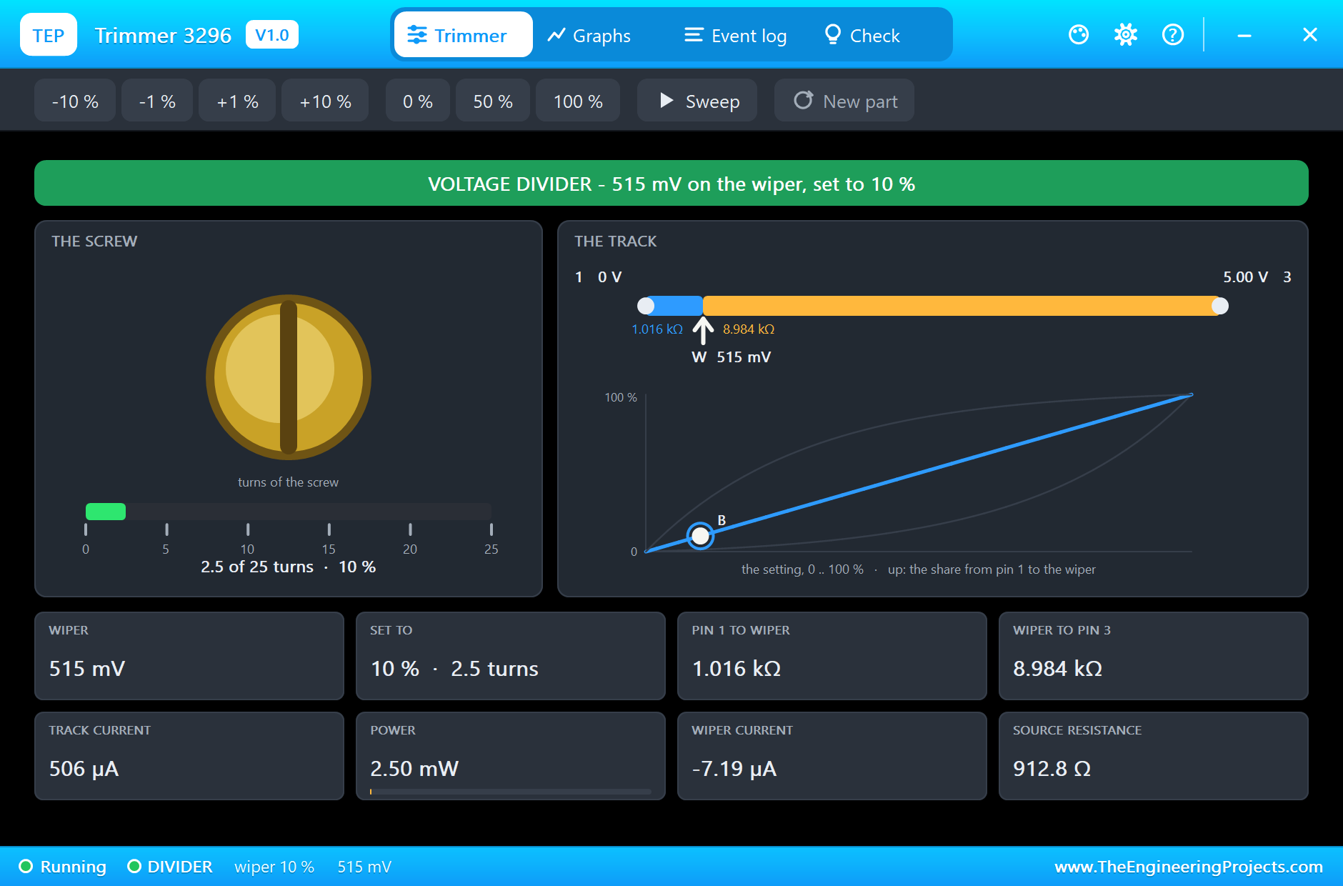
Now turn RV1 down. Click -10 % four times on its pop-up, which is ten turns of the screw, or click the left half of its box ten times. With every step the text grows darker, and at 0.51 V it is crisp and white. Here is the complete circuit, truly running, with a perfect contrast:
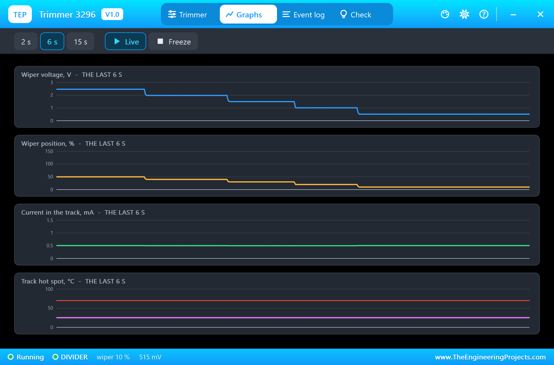
RV1's pop-up now shows 2.5 of 25 turns, with 1.016 kohm between pin 1 and the wiper. The Graphs page shows each of the four steps on the wiper voltage, from 2.47 V down to 0.51 V:
Too Far
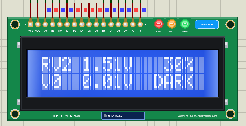
Turn RV1 all the way down, to 0 %, and V0 falls to 0.01 V. The text is still there, but every empty dot has darkened too, and the screen fills with grey blocks. That is too much contrast, and on a real LCD it looks exactly the same:
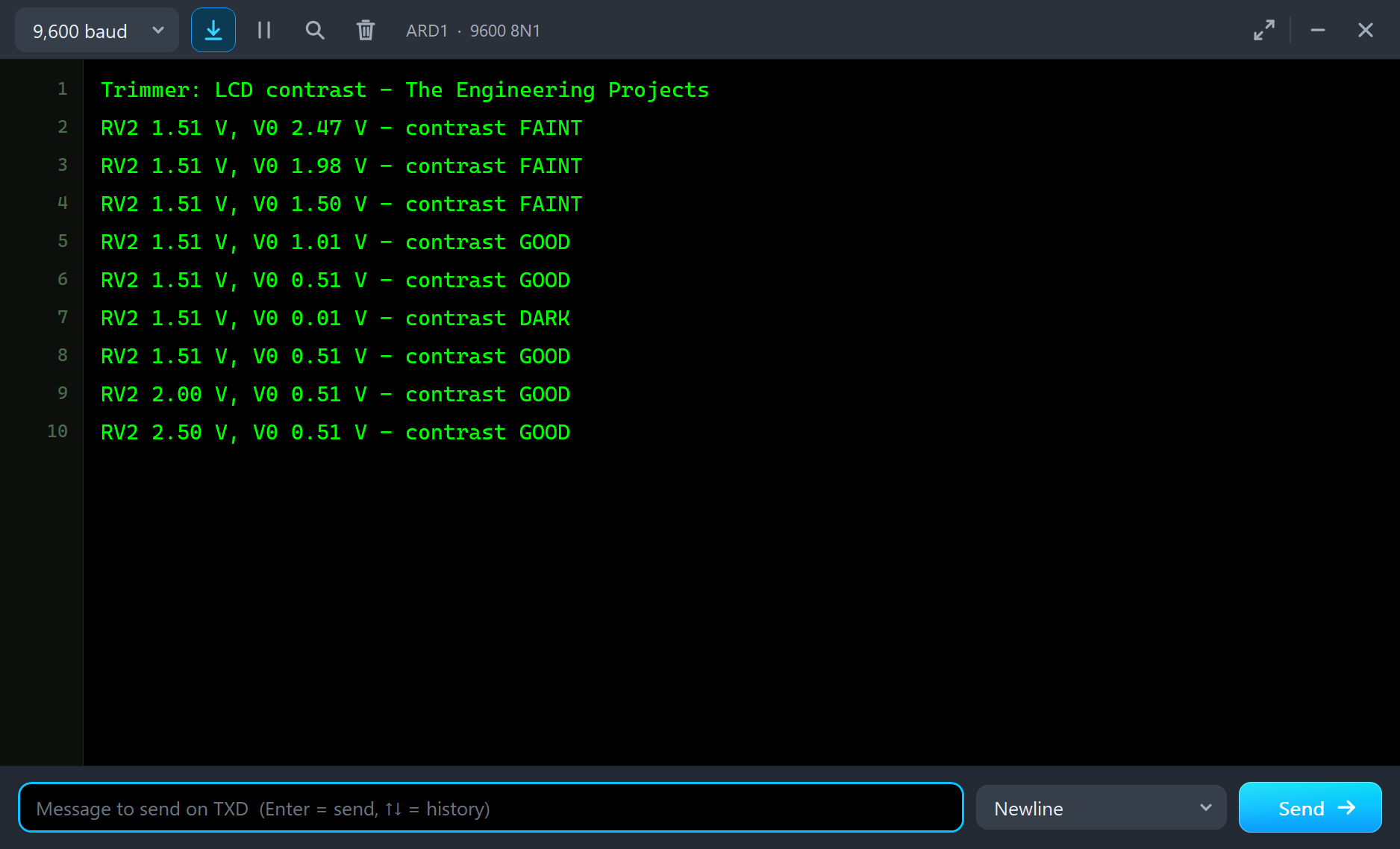
The monitor recorded the whole adjustment, every step of it, from FAINT through GOOD to DARK and back:
The Graphs, the Log and the Check Page
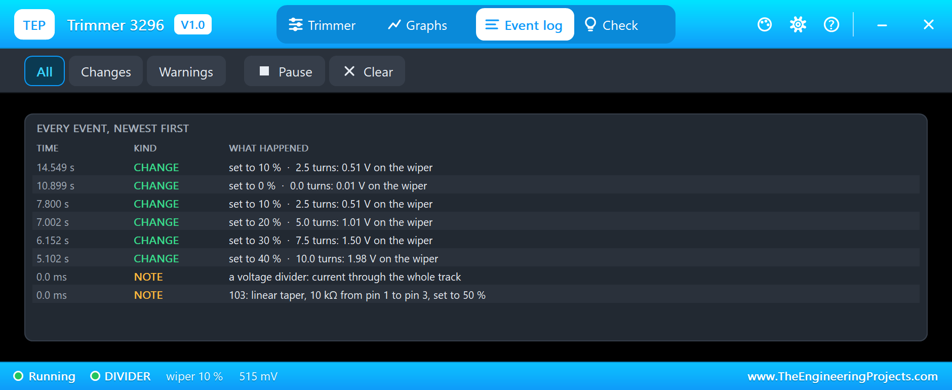
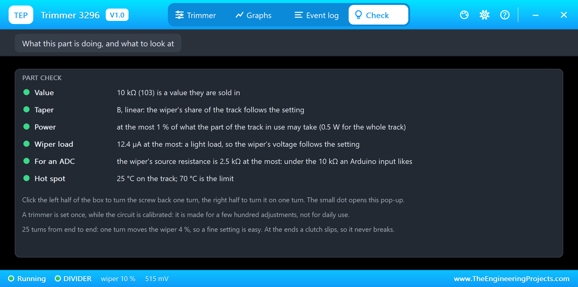
The Graphs page shows the four steps down as a clean staircase on the wiper voltage and the position, while the track current stays at about 0.5 mA, as it always does in a divider. The Event log lists every setting with the wiper voltage it gave. The Check page looks at the value, the power, the load on the wiper and the source resistance:
Turning Them by Hand
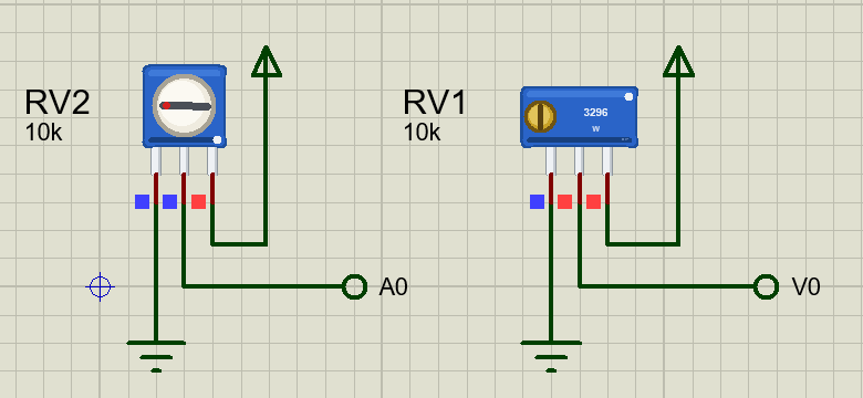
You never need the chips. We tested both trimmers with a real mouse. One click on the right half of RV1's box turned the screw on one turn, from 50 % to 54 %, and its wiper rose to 2.66 V. One click to the left of RV2's rotor pointed its red dot at nine o'clock: 13 %, and 0.66 V on its wiper:
Try It Yourself
- Find the lowest and the highest V0 that still read as GOOD, and compare them with the limits in the sketch.
- Turn RV1 back up, one turn at a time, and watch the text fade on the LCD.
- Swap RV1 for the 3362, and see how much harder it is to set V0 to a tenth of a volt with a single turn.
- Rewire RV2 as a variable resistor in series with an LED, and watch the Check page near the end of its travel.
- Use RV2 to set a threshold, and make the LCD print ALARM when RV2 passes it.
Ideas to Extend the Demo
- Calibrate a voltage divider so the Arduino reads a 12 V battery correctly.
- Set the brightness of the LCD backlight with a trimmer and a transistor.
- Build a comparator threshold with a trimmer, like the ones on sensor modules.
- Use two trimmers for the offset and the gain of a sensor reading in the sketch.
Your Own Sketches
The demo sketch is in the zip file, and you can change it in the Arduino IDE. New to Arduino? Start with our Arduino Tutorial for Beginners. Export the compiled binary, and set the UNO's PROGRAM property to the new file. Our guide on How to get the HEX file from Arduino shows you where the file ends up.
Things to Know Before Using a Real Trimmer
- Use the right screwdriver: a small, insulated one. A metal blade can short the wiper to something next to it.
- Count the turns on a 3296: its clutch slips at both ends, so it never tells you when you hit the stop.
- Set it and leave it: a trimmer is made for a few hundred adjustments, not for daily use.
- Pick 10k for an LCD: it is the usual value for the contrast, and it suits an Arduino input as well.
- Watch the power as a variable resistor: only part of the track takes the current, so add a fixed resistor in series.
Troubleshooting
- The LCD is blank or faint: V0 is too high. Turn RV1 down, the left half of its box.
- The LCD shows grey blocks: V0 is too low. Turn RV1 up a little.
- A click does nothing: the simulation is not running, or the click landed on the small dot, which opens the pop-up.
- The track burnt: it was a variable resistor with too much current. Click New part, and add a series resistor.
- The part is not simulated:
TEPTRIM.DLLis missing from MODELS and from the project folder.
Limitations of the Simulation
- The tolerance spread, the temperature coefficient and the wear of the track are left out.
- The 3296's clutch is not felt: the screw simply stops turning the wiper at either end.
- The setting stays at the nearest 5 % after Stop, even if you set it to 47 %.
- Arduino is a name of Arduino; this library is not made or endorsed by Arduino or Labcenter.
- Tested in Proteus 8.5 in November 2026 (the demo as shipped). Proteus 7 is not supported.
So, that was all about the Trimmer Potentiometer Library for Proteus. I hope it saves you from at least one blank LCD, and that a click on the screw feels a little like the real thing. If you have any questions, ask in the comments and I will help you out. Till the next tutorial, take care and have fun!