Interfacing of Multiple Ultrasonic Sensor With Arduino
Hello friends, hope you are having fun and enjoying life. Today, I am gonna post about interfacing of multiple Ultrasonic sensor with Arduino. In the previous post, we have seen Interfacing of Ultrasonic Sensor With Arduino and in this post I have interfaced single ultrasonic sensor but in projects especially related to robotics, we have to interface multiple ultrasonic sensors. For example you have an obstacle detection robot, now in order to detect obstacle in front of robot you have to place once sensor on the front side but now you can't detect any object present on left or right side of your robot, so you have to place two sensors one on the left side of robot and one on the right side so in this project you need to use total three ultrasonic sensors, one on the front, one on left and one on right side of robot. Similarly, in another project I have to move the robot in a maze having walls on the side of robots, and my task was to move the robot straight within these walls without hitting the walls. In that case, I also used two ultrasonic sensors on both sides of robot and then applied PID algorithm in order to avoid hitting the walls. So, in short its a common practice to use multiple ultrasonic sensor with Arduino and today we are gonna have a look at how to do it.
I have posted about the basics of Ultrasonic sensor and how it works in my previous post so I am not gonna go into that detail. If you haven't read it then I recommend that you should first read Interfacing of Ultrasonic sensor with Arduino. Now, let's get started with Interfacing of multiple ultrasonic sensor with arduino, which isn't that difficult. :)
Note:
- Other Proteus Libraries are as follows:
- I have also posted more examples on Ultrasonic Sensor Simulation in Proteus, have a look at them and you will get complete understanding of this sensor.
- Moreover, for hardware implementation of Ultrasonic Sensor with Arduino, check below posts:
Interfacing of Multiple Ultrasonic Sensor With Arduino
- Let me first summarize the working of ultrasonic sensor again. With ultrasonic sensor, what we need to do is to generate a trigger signal on its trigger pin for around 10 microsecond.
- As soon as the ultrasonic sensor gets this trigger signal, it sends out an ultrasonic signal.
- This ultrasonic signal then hits something and bounced back.
- Now, in order to check this bouncing signal, we have to read the Echo pin and check for how long it remains HIGH, and on the basis of this duration we calculate our distance with the object.
- This is the process for single ultrasonic sensor and when we are using multiple ultrasonic sensors, what we need to do is simply repeat the whole procedure for all the sensors one by one.
- First of all, we will generate the trigger pulse for first sensor and the read its echo pin and get the distance, then we generate the trigger pulse for second sensor and read its echo pin and so on for the third.
- So, here I am gonna use three ultrasonic sensor and the circuit diagram is shown below:
- I have tried my best while designing this image to make it simple but as there are too much wires so it has become a little complex.
- I am pointing out the pin configuration here so it will be easy for you to interface your sensors with arduino. The pin configuration is as follows:
- Vcc of all sensors will go into +5V of Arduino.
- GND of all sensors will go into GND of Arduino.
- Trig Pin of first sensor into Pin # 3 of Arduino.
- Echho Pin of first sensor into Pin # 2 of Arduino.
- Trig Pin of second sensor into Pin # 4 of Arduino.
- Echo pin of second sensor into Pin # 5 of Arduino.
- Trig Pin of third sensor into Pin # 7 of Arduino.
- Echo pin of third sensor into Pin # 8 of Arduino.
- After connecting the pins as discussed above, now copy the below code and upload it in your arduino board.
- After uploading the code in your arduino, open the Serial Terminal of Arduino software and you will start receiving the distances for all the three sensors.
#define trigPin1 3
#define echoPin1 2
#define trigPin2 4
#define echoPin2 5
#define trigPin3 7
#define echoPin3 8

long duration, distance, RightSensor,BackSensor,FrontSensor,LeftSensor;

void setup()
{
Serial.begin (9600);
pinMode(trigPin1, OUTPUT);
pinMode(echoPin1, INPUT);
pinMode(trigPin2, OUTPUT);
pinMode(echoPin2, INPUT);
pinMode(trigPin3, OUTPUT);
pinMode(echoPin3, INPUT);
}

void loop() {
SonarSensor(trigPin1, echoPin1);
RightSensor = distance;
SonarSensor(trigPin2, echoPin2);
LeftSensor = distance;
SonarSensor(trigPin3, echoPin3);
FrontSensor = distance;

Serial.print(LeftSensor);
Serial.print(" - ");
Serial.print(FrontSensor);
Serial.print(" - ");
Serial.println(RightSensor);
}

void SonarSensor(int trigPin,int echoPin)
{
digitalWrite(trigPin, LOW);
delayMicroseconds(2);
digitalWrite(trigPin, HIGH);
delayMicroseconds(10);
digitalWrite(trigPin, LOW);
duration = pulseIn(echoPin, HIGH);
distance = (duration/2) / 29.1;

}
- The code is quite similar to the one we used while interfacing single ultrasonic sensor with arduino, the only thing we changed here is the repetition.
- Before, we were using the same function SonarSensor() but calling it only once for our single sensor interfaced with arduino but now we are calling it three times for all the three sensors.
- Its kind of a generic code, you can interface more sensors with it if you want and what you need to do is only calling this function for the next interfaced sensor.
That's all for today, I think we have posted a lot on the ultrasonic sensor so I am not gonna post any more tutorial on this sensor and now I will start writing on some other sensor. You should also have a look at
Arduino Projects for Beginners. Thanks for reading and share it with your friends and help us grow. :)
Interfacing of Ultrasonic Sensor With Arduino
Today, we are gonna have a look on How to Interface Ultrasonic Sensor with Arduino. Few days ago, I have posted a complete tutorial on How to Use Ultrasonic Sensor Library in Proteus and later I have posted different examples on How to Simulate Ultrasonic Sensor in Proteus. Those posts were about Proteus Simulations and weren't about hardware interfacing, so I thought today let's interface it in hardware.
Simulation is a good starting point for projects but they are really far away from real world. It happened to me a lot of times that my simulations are working perfectly fine but when I design the same circuit in hardware then it says no I am not gonna work. :) So, the bottom line is never trust simulations, unless you properly test it on hardware. So, today I am gonna interface an Ultrasonic sensor with arduino and will check its output on the Arduino Serial Terminal.
1. Introduction to Ultrasonic Sensor
- "Ultrasonic Sensor HC-SR04 is a simple sensor which emits Ultrasonic Radiations from its transmitter and is used for measuring the distance between sensor itself and any obstacle in front of it. The sensor has a transmitter and a receiver on it."
- This sensor consists of four pins, which are:
- Vcc (+5V) : You need to provide +5V at this Ultrasonic Sensor HC-SR04 Pin.
- Trig (Trigger) : It's a trigger Pin where we need to provide a trigger after which this sensor emits ultrasonic waves.
- Echo : When Ultrasonic waves emitted y the transmitter, hit some object then they are bounced back and are received by the receiver and at that moment this echo Pin goes HIGH.
- GND : We need to provide ground to this PIN of HC-SR04 Ultrasonic Sensor.
Note:
- If you haven't bought your components yet for this project, then you can buy them from these reliable sources:
| [ultimate_spacer height="13"]
|
[ultimate_spacer height="13"]
|
- Trigger pin is an output pin while the Echo pin is an input pin, we will discuss them in Working section in detail.
- Moreover, it requires +5V to start operating.
- It is normally used to detect objects in front of it or to measure the distance between different objects.
2. Working of Ultrasonic Sensor
- Its working is quite simple, as discussed above, it has a trigger and an echo pin.
- A signal of +5V is sent over to Trigger pin for around 10 microseconds in order to trigger the sensor.
- When ultrasonic sensor gets a trigger signal on its trigger pin then it emits an ultrasonic signal from the transmitter.
- This ultrasonic senor, then goes out and reflected back after hitting some object in front.
- This reflected ultrasonic signal is then captured by the receiver of ultrasonic sensor.
- As the sensor gets this reflected signal, it automatically make the Echo pin high.
- The time for which the Echo pin will remain HIGH, depends on the reflected signal.
- What we need to do is, we need to read this time for which the echo pin is high, which we are gonna do in our next section.
- So, let's have a look at Ultrasonic Sensor Arduino Interfacing.
3. Interfacing of Ultrasonic Sensor With Arduino
- Now we have seen the working of Ultrasonic sensor, so we have some idea what we need to do in order to get the values from it. Let's now have a look at Ultrasonic Sensor Arduino Interfacing.
- First of all, we need to generate a signal of 10 microsecond and then send it over to trigger pin.
- After sending the trigger pin we then need to read the echo pin and wait for it to get HIGH.
- Once it got HIGH then we need to count the time for how long it remained HIGH.
- On the basis of this time, we are gonna calculate the distance of the object from the ultrasonic sensor.
- So, first of all, interface your ultrasonic sensor with arduino as shown in below figure:
- Now, use the below code and upload it your arduino board. After uploading the code, open your serial terminal of Arduino software and you will start receiving the values.
#define trigPin1 8
#define echoPin1 7

long duration, distance, UltraSensor;

void setup()
{
Serial.begin (9600);
pinMode(trigPin1, OUTPUT);
pinMode(echoPin1, INPUT);
}

void loop() {
SonarSensor(trigPin1, echoPin1);
UltraSensor = distance;
Serial.println(UltraSensor);
}

void SonarSensor(int trigPin,int echoPin)
{
digitalWrite(trigPin, LOW);
delayMicroseconds(2);
digitalWrite(trigPin, HIGH);
delayMicroseconds(10);
digitalWrite(trigPin, LOW);
duration = pulseIn(echoPin, HIGH);
distance = (duration/2) / 29.1;
delay(100);
}
- Now if you check in the SonarSensor() function, we are generating a pulse of 10 microsecond and sending it to trigPin, which is the trigger pin of our ultrasonic sensor.
- After sending this pulse weare using a funcion pulseIn() , its a builtin arduinofunction and is used to check for how long the echoPin remains HIGH.
- This value is further saved in the duration value and after that we have divided this duration by 2 because the pulse is first sent and then received so in actual it covers double distance, so we need to divide it by 2 in order to get distance between object and the sensor.
- Furthermore, it is again divided by 29.1, which is basically the speed of ultrasonic sound and finally we saved it in a variable named distance which is now in centimeters.
- After uploading the sketch in Arduino, you need to open the Serial Terminal and you will start receiving the values of distance.
That's all for today. I hope you have enjoyed this Interfacing of Ultrasonic Sensor with Arduino. It wasn't that difficult, in our coming post we are gonna
Interface Multiple ultrasonic sensors with Arduino and will get their values on the serial terminal. Till then Take care and have fun !!! :)
Receive SMS with AT Commands using Sim900 and Arduino
Update: I have updated the code and removed the bug. Thanks for informing. Now this code will work perfectly.
Buy This Project
Hello friends, hope you all are fine and having good health. Today, as the name suggests, I am gonna post on how to Receive SMS with AT Commands using Sim900 and Arduino. I have already posted a tutorial on How to Send SMS with Arduino UNO and Sim900, so now we are gonna check the opposite. Sending SMS is quite easy, you just need to write some AT commands and write the message you wanna send and hit the Cntrl + Z and it will be sent. But receiving a text message on your SIM900 shield is a bit difficult because now you need to place a check when user will send a message. So, ideally whenever anyone send a message to your SIM900 module, you should get notified. Today, we are gonna cover this how to receive SMS with AT Commands in detail.
Now, after you get notified, there's a need to read the message as well and also who has sent this message. So, we are also gonna cover it today. So, first of all we will place a check that whenever someone sends a message to our SIM900 module, we get notified and after that we will extract the message and the mobile number of sender. We have designed this code after a lot of effort that's why this code isn't free but we haven't placed a very small amount of $20 so that engineering students can also buy it easily. We can also interface our GSM board with other microcontrollers like PIC Microcontroller as well as 8051 Microcontroller. I have also posted tutorial on How to Receive SMS with SIM900 & PIC Microcontroller and How to Send SMS with PIC Microcontroller so if you are working on PIC Microcontroller then you must give it a look. So, let's get started with How to receive SMS with AT Commands using SIM900 and Arduino.
You must also check GSM Library for Proteus, using this library you can easily simulate your GSM module in Proteus ISIS. Moreover, also have a look at Send SMS with Sim900D in Proteus ISIS in which I have designed a simulation of sms sending in Proteus ISIS.
Receive SMS with AT Commands using Sim900 and Arduino
- There are many GSM modules available in the market so it doesn't matter which one you are using unless its having SIM900 module in it.
- I have explained in my previous post that all GSM modules work on AT commands, so here first of all we are gonna have a look on AT commands we are gonna use for receiving the SMS.
- ATE0 - IT is used to turn off the Echo of GSM shield.
- AT - Just to check that your GSM module is working fine.
- AT + CMGF = 1 - This command will convert the message style to text. In other words we are telling our shield that we are expecting a text message.
- AT+CNMI=1,2,0,0,0 - This command will alert our GSM shield and now whenever it will receive message, it will automatically send an alert on the serial port.
- We are gonna use these four commands in our code and we will be able to receive text message on the GSM shield.
- Remember we have to put Enter after each of the above AT commands in order to execute it.
- Below is the first phase of the code and as you can see in this code we are simply sending these four commands serially from arduino to GSM shield.
- These are two functions I have shown below, the first function is Config() which is simply sending the commands via serially and then the Response() function which is called after every AT command and is receiving the response of that AT command.
- So, here's the partial code for How to Receive SMS with AT Commands using Sim900 and Arduino.
void Config()
{
delay(1000);
Serial.print("ATE0r");
Response();
Serial.print("ATr");
Response();
Serial.print("AT+CMGF=1r");
Response();
Serial.print("AT+CNMI=1,2,0,0,0r");
Response();
}

void Response()
{
int count = 0;
Serial.println();
while(1)
{
if(Serial.available())
{
char data =Serial.read();
if(data == 'K'){Serial.println("OK");break;}
if(data == 'R'){Serial.println("GSM Not Working");break;}
}
count++;
delay(10);
if(count == 1000){Serial.println("GSM not Found");break;}

}
}
- The response of these commands is shown below on the Serial Monitor of Arduino.
- For each AT command, we get a response "OK" from the GSM shield.
- Now, I know that I have sent all these four AT commands and my GSM shield is ready to receive the text messages and will inform me.
- So, when you send a message to your GSM shield, it will give a notification as shown in the below figure:
- Each message received by SIM900 module is start with "+CMT" and after that it has the mobile number of the sender and at the end lies the body of the message, which in our message is "www.TheEngineeringProjects.com"
- So now let's extract this mobile number and the text body from this CMT string.
Getting the SMS Text & Sender Mobile Number
- Till now we have learnt How to Receive SMS with AT Commands using Sim900 and Arduino and send you notification over the serial monitor.
- Now we have to place some checks in our code so that we could be able to get the required data out of this string.
- In order to do so, I am gonna first save this CMT string into an array, which I named as RcvdMsg[index].
- But before saving the data into this string, first I need to make sure that I am actually getting the requried string, that's aso possible that I am receving some garbage values.
- So, I placed a check first, which is checking for these four characters "+CMT", and when I got these character on my serial terminal I got sure that I have the string ready so I made the index = 0 and starting receving the string.
- Next thing I need to do is make sure that I have got the complete string, that was really a tricky part as there's no end character in the string.
- So, I used "n" null character for that. If you check the string then you can see that we are getting two null characters in complete string.
- I placed this check that when I get 2 null characters means I have got the complete string so I stopped receving the string.
- After that I simply count the charaters, in my string the sender mobile number is at posting 4 to 16 so I made a loop and save it in another array. and similarly did for the message text.
- Now when I send message after uploading this final code into my Arduino board, I get the below result on my Serial Monitor.
- Isn't it cool :) So, now we have separated the complete text as well as the sender's mobile number from our GSM string and we can use it anywhere we want.
- We can use this mobile number in the previous post code and can reply some text back and can also give a missed call to the user, anything we want. I am gonna post on How to send a call using SIM900 in the next post.
- You can buy the codefor How to Receive SMS with AT Commands using Sim900 and Arduino from our shop by clicking the below button:
Buy This Project
- I have highlighted all the functions in the code.
- As I always say, understand it first and then write on your own and do mistakes so that you learn.
That's all for today. I hope you have enjoyed this project named Receive SMS with AT Commands using Sim900 and Arduino. I will meet you guys in the next post. Till then have fun !!! :)
Ultrasonic Sensor Simulation in Proteus
Hello friends, a few days ago I posted an Ultrasonic Sensor Library for Proteus, using which one can easily simulate ultrasonic sensor in Proteus. The post was highly praised by the reader and I have received quite good feedback from the followers. So, I thought of sharing some more examples related to it so that users can get a complete understanding of how to use Ultrasonic sensors in Proteus. Today, we are gonna have a look on different Ultrasonic Sensor Simulation in Proteus. If you haven't read the previous post then first have a look at it because without the installation of Ultrasonic Sensor Library in Proteus, you won't be able to use these examples. Ultrasonic Sensor is used widely in Embedded Systems.
Today, I am gonna share three examples of Ultrasonic Sensor Simulation in Proteus, which will be enough for you guys to get the overview of this sensor. I have also attached these simulations below and you can easily download them but as I normally advise, it's better to design these simulations by yourself and write your own code as it will help you understand it more clearly. If you don't make mistakes, you won't learn from it. I am gonna share below three examples of Ultrasonic Sensor:
Note:
- Other Proteus Libraries are as follows:
- I have also posted more examples on Ultrasonic Sensor Simulation in Proteus, have a look at them and you will get complete understanding of this sensor.
- Moreover, for hardware implementation of Ultrasonic Sensor with Arduino, check below posts:
Ultrasonic Sensor Simulations in Proteus using Button
- In this tutorial, we are gonna use three buttons and using these buttons we will control our ultrasonic sensor.
- Think of these buttons as three obstacles, which are placed at different distances, if we hit the first button then first obstacle is reached, if we hit second then second obstacle and same as for third.
- So, open your Proteus ISIS and if you have already installed ultrasonic library for Proteus then design your Ultrasonic Sensor Simulation in Proteus as shown in below figure:
- Now open your Arduino software and paste below code in it and get your hex file to upload in this simulation.
Note:
const int pingPin = 7; const int echoPin = 6; void setup() { Serial.begin(9600); } void loop() { long duration, inches, cm; pinMode(pingPin, OUTPUT); digitalWrite(pingPin, LOW); delayMicroseconds(2); digitalWrite(pingPin, HIGH); delayMicroseconds(10); digitalWrite(pingPin, LOW); pinMode(echoPin, INPUT); duration = pulseIn(echoPin, HIGH); inches = microsecondsToInches(duration); cm = microsecondsToCentimeters(duration); Serial.print(inches); Serial.print("in, "); Serial.print(cm); Serial.print("cm"); Serial.println(); delay(100); } long microsecondsToInches(long microseconds) { return microseconds / 74 / 2; } long microsecondsToCentimeters(long microseconds) { return microseconds / 29 / 2; } - After adding the hex file in this simulation, hit the RUN button and if everything goes as expected then you will get a simulation as shown in the below figure:
- You can download this simulation along with Arduino code and the hex file by clicking below button:
Download Ultrasonic Sensor simulation in Proteus Using Button
Ultrasonic Sensor Simulations in Proteus as Proximity Switch
- I have explained the first example in detail so I am not gonna much explain this one.
- In this example, we are using the Ultrasonic Sensor as a Proximity Switch, whenever any obstacle comes in the way of ultrasonic sensor, it will automatically give an indication.
- As you can see from the figure below that we are using a variable voltage source for the analog pin of ultrasonic sensor.
- So, first of all design a simulation as shown in the below figure:
- Now upload the Arduino hex file for this example, which is attached below along with the code and this simulation.
- After uploading the hex file, hit the RUN button and if everything is in your favor, then you will see results similar to below figure:
- As you can see in the above figure, we are sending a Ping from Ultrasonic Sensor and in the programming code we have placed an alarm at a specified distance, so whenever any object comes in that range, our program will give us Alarm, you could also use Buzzer in Proteus.
- You can download this Proteus Simulation along with Arduino Code and hex file by clicking on this below button:
Download Ultrasonic Sensor Simulation in Proteus As Proximity
Ultrasonic Sensor Simulations in Proteus using Switch
- Here's the third and last example of Ultrasonic Sensor simulation in Proteus.
- In this simulation, we are using a switch and controlling the Ultrasonic with that Switch.
- There are total four states for that Switch, which determines what should be the voltage on the analog pin of Ultrasonic Sensor.
- I have also placed a oscilloscope in this simulation which will give you the voltage state for this switch, to get you an idea what's the voltage pattern coming to ultrasonic sensor, its mainly just for understanding and testing.
Note:
- Now upload your Arduino hex file in it and hit the RUN button and you will see something like this:
- As you can see above, the virtual terminal is showing the distances while the oscilloscope is giving us state of switch, play with it and you will learn more and if still confused then ask in comments.
- You can download the Proteus simulation of this example along with Arduino hex file and code by clicking on the below button.
Download Ultrasonic Sensor Simulation in Proteus Using Switch
That's all for today, hope you guys have learn something today, if you have any problem or question, do ask in comments and I will try my best to resolve them. Take care :)
Ultrasonic Sensor Library for Proteus
Hello friends, hope you all are fine and having good health. In today's post, I am going to share an Ultrasonic Sensor Library for Proteus. A few days ago, I posted a tutorial on Arduino Library for Proteus, and today I am going to share the new Ultrasonic Sensor Library for Proteus. Using this library, you can easily interface Ultrasonic Sensors with different Microcontrollers like Arduino, PIC Microcontroller etc.
First of all, let's have a brief introduction to ultrasonic sensor. In an ultrasonic sensor, there are two nodes available, one is the transmitter while the other is the receiver. The transmitter sends an ultrasonic wave and this wave strikes any hindrance present in front of it and then bounces back. This bounced ultrasonic sensor is then captured by the receiver and on the basis of the time taken by this wave to return, the sensor calculates the distance of that obstacle from that sensor.
The Ultrasonic sensor is usually used for detecting the obstacle in the path and also to find the distance between the sensor and the obstacle. The ultrasonic sensor normally used is HC-SR04, which we have designed in this library. Let's get started with Ultrasonic Sensor Library for Proteus, in this library we have used an extra pin on the ultrasonic sensor, which is an analog pin. The voltage on that pin is used to detect how close an object is because it's a simulation and we can't place an actual object in front of the simulated sensor. Moreover, you should also have a look at this Home automation Project using XBee & Arduino, I have used this ultrasonic sensor in that project.
I hope you are going to enjoy this library. This library is designed by our team after a lot of effort, if you have any feedback to improve, please let us know. So, let's get started with Ultrasonic Sensor Library for Proteus and its interfacing with Arduino.
Note:
- Other Proteus Libraries are as follows:
- Moreover, for hardware implementation of the Ultrasonic Sensor with Arduino, check below posts:
- I have also posted more examples of Ultrasonic Sensor Simulation in Proteus, have a look at them and you will get a complete understanding of this sensor.
Ultrasonic Sensor Library For Proteus
- First of all download this Ultrasonic Sensor Library for Proteus, by clicking on the below button.
Ultrasonic Sensor Library for Proteus
- In this ultrasonic sensor library for Proteus, you will find three files which are:
- UltrasonicTEP.IDX
- UltrasonicTEP.LIB
- UltrasonicTEP.HEX
- Now, place these three files in the library folder of your Proteus software.
Note:
- Now start your Proteus software and in the components list, search for the Ultrasonic sensor and place it in your workspace as shown in the below figure:
- Now we have our ultrasonic sensor in Proteus but if you run it then it won't work as we haven't yet added any functionality in it.
- So, in order to add the functionality double click this ultrasonic sensor and open its properties.
- In properties, select the Program File section and browse to UltrasonicTEP.HEX file and upload it as shown in below figure:
- Now our ultrasonic sensor is ready to be used.
- Now let's make a simple example for an ultrasonic sensor, so that you get an idea of how to use it in Proteus.
Ultrasonic Simulation in Proteus
- After adding the Ultrasonic Sensor Library for Proteus, open your Proteus ISIS software or restart it, if it's already open.
- Now search for the below components in the Proteus Components Library and add them in your workspace as shown in the below figure.
Components Used
Here's the list of components, which I have used for designing this Proteus Simulation:
Proteus Simulation
- After adding these components, now design a simulation as shown in the below figure:
- Now in this example, I am receiving data from Ultrasonic Sensor and then printing this data over Virtual Terminal in Proteus, if you are not much familiar with Virtual Terminal, then read How to use Virtual Terminal in Proteus ISIS.
- Now open your Arduino software and paste the below code in it and compile it to get the hex file, read Arduino Library for Proteus to know how to get the Arduino Simulation in Proteus.
- You must also read How to get the hex file from Arduino Software.
const int pingPin = 7; // Trigger Pin of Ultrasonic Sensor
const int echoPin = 6; // Echo Pin of Ultrasonic Sensor

void setup()
{
Serial.begin(9600); // Starting Serial Terminal
}

void loop()
{
long duration, inches, cm;
pinMode(pingPin, OUTPUT);
digitalWrite(pingPin, LOW);
delayMicroseconds(2);
digitalWrite(pingPin, HIGH);
delayMicroseconds(10);
digitalWrite(pingPin, LOW);

pinMode(echoPin, INPUT);
duration = pulseIn(echoPin, HIGH);
inches = microsecondsToInches(duration);
cm = microsecondsToCentimeters(duration);

Serial.print(inches);
Serial.print("in, ");
Serial.print(cm);
Serial.print("cm");
Serial.println();

delay(100);
}

long microsecondsToInches(long microseconds)
{
return microseconds / 74 / 2;
}

long microsecondsToCentimeters(long microseconds)
{
return microseconds / 29 / 2;
}
- It's quite a simple code and is self-explanatory, if you still got some trouble then ask in the comments and I will reply to them. I have simply used the ping example in Arduino Examples and slightly modified it.
- After getting the hex file, now upload it to Arduino in Proteus by clicking the properties.
- Click on the Start button and if everything's gone fine then you will see an output as shown in the below figure:
- As you can see in the above figure, the virtual terminal is showing distance values, now this value depends on the variable resistance attached to the ultrasonic sensor.
- As you change the value of the variable resistance, the voltage on that particular pin will also change and on the basis of that, you will get the distance in inches and centimeters on the virtual terminal.
- Arduino code and hex file along with the Proteus Simulation for this ultrasonic example are attached below. You can download it by clicking on the below button but I would suggest you to design it on your own, it will help you in learning.
- You should also have a look at these Arduino Projects for Beginners.
Download Code and Proteus Simulation
That's all for today, in the coming post I am gonna share some more examples of how to use ultrasonic sensor in Proteus. Till then take care and have fun.
Logical Gates in Ladder Logic for PLC
In the previous post Logical Gates in Ladder Logic for PLC, we had an overview of what is Ladder Logic programming and we have also implemented three basic Logical gates in Ladder Logic form. Today, we are gonna have a look at some complex Logical Gates in Ladder Logic for PLC. So, I hope till now you guys have basic knowledge of Ladder Logic and can implement complex logical gates in it. If you haven't read the previous post then must read because without that knowledge you won't understand this post.
In today's post we are gonna implement few complex logical gates. Its not gonna be much difficult if you have the basic concepts. I am just pointing out few important points here. While implementing any gate in ladder logic, always consider rung as an electrical line having HIGH voltage at one end and LOW voltage at the other, while the inputs are simple switches. Voltage will be supplied to the output only when switch is closed i.e. input is HIGH, otherwise the output will remain OFF. You should also have a look at Introduction to Logic Gates.
You have seen in previous post, while implementing OR gate we have used a second switch in parallel which ends at the first rung so overall its a single rung having two inputs in parallel so input can come either from first switch or from second one. So, now let's start implementing some complex logical gates in Ladder Logic for PLC. Today, we are gonna implement these logic gates:
- NAND Logical gate in Ladder Logic for PLC
- NOR Logical gate in Ladder Logic for PLC
- XOR Logical gate in Ladder Logic for PLC
- XNOR Logical gate in Ladder Logic for PLC
NAND Logical gate in Ladder Logic for PLC
- NAND gate is another type of logical gate, which is normally used. NAND gate is nothing but a simple NOT of AND gate. In simple words, if we add a NOT gate in front of AND gate, we get NAND gate. The truth tablel of NAND gate is shown in the below figure:
- It is quite obvious from the truth table of NAND gate that the output will be OFF only when both the inputs will be ON otherwise output will remain ON. So, now lets implement this gate in ladder logic programming.
- The below image shows the implementation of NAND logical gate in Ladder Logic form:
- Now, if you understand the above figure, then its quite obvious. We have used both inputs in normally closed form so when both inputs are OFF the output will be ON. If we get X0 ON then in still we will get the HIGH voltage from X1. If we make X1 ON then we get HIGH voltage from X0, but if we get both X0 and X1 ON then our Y0 will get OFF. Again we are using inputs in normally closed form so when our actual input is OFF then our X0 is closed. :)
NOR Logical gate in Ladder Logic for PLC
- In NOR gate, we simple place a NOT gate in front of OR gate. Its truth table is shown in below figure:
- From the truth taable of NOR gate, its quite obvious that its output will be ON when both of its input goes OFF otherwise the output will remain ON. Lets implement this NOR logical gate in Ladder Logic diagram.
- The below figure shows the NOR logical gate in ladder logic diagram:
- If you got the ladder logic form of NAND gate, then its not gonna be much problem. Simple two normally closed inputs are placed in series, so now when any of them gets ON, then output will get OFF.
Note:
- If you have noticed, whenever NOT gate is involved somewhere, we use normally closed inputs.
XOR Logical gate in Ladder Logic for PLC
- The truth table of XOR gate is shown in below figure:
- From the truth table, we can get this thing that, output will ON only when the inputs are in opposite states and output will be OFF when inputs are in same state.
- The ladder logic implementation of XOR gate is shown in below figure:
- Now it has gone a little complex but lets understand how's its working. We have placed X0 and X1 in series and also in parallel, but in first string X0 is normally open and X1 is normally closed while in second string X0 is normally closed and X1 is normally open.
- Now, what we need to do is if both inputs are in same state we need to turn OFF the output. That's what we are doing in above logic diagram. Let's say X0 and X1 both are OFF then the normally open switches will be OFF and they wont let the HIGH voltage pass and hence our Y0 will remain OFF. And if both are ON then the normally closed will be OFF and again Y0 will remain OFF.
- Now if X0 is ON and X1 is OFF, then the first string will connect and our output will ON, and if X0 is OFF while X1 is ON then our second string will connect and will make our output ON. Quite simple and easy.
XNOR Logical gate in Ladder Logic for PLC
- Last but not the least XNOR gate, if we add NOT gate in front of XOR gate we get XNOR gate, let's have a look at its truth table below:
- So, in XNOR gate, we get our output ON when both inputs are in same state otherwise its OFF. Let's implement it in ladder logic form below:
- Now in this ladder logic diagram, we are getting introduced with a new symbol, till now we have used normally open output but here for the first time, we are using normally closed output Y0.
- It's exactly the same logic as we used for XOR gate, but the only difference is ere we are using normally closed output. So, simple when the output is gets ON, its actually OFF and when it gets OFF its actually ON ;)
- I hope now you got the clear concept of How to do programming using Ladder Logic and what's its difference with Microcontrollers like Arduino or PIC Microcontroller etc.
That's all for today, hope I have conveyed some knowledge. If you are new to PLC programming then you won't get it in the first attempt so my suggestion is give it some time, read it again and again and you will feel better :) I am not gonna post more about Ladder Logic designing, instead in the next post we are gonna have n overview of PLC simulation software in which we design this ladder logic diagrams. Till then take care and have fun :)
Introduction to Ladder Logic for PLC
Hello everyone, I hope you all are doing great. In today's tutorial, I am going to share the detailed fIn the previous post, we have seen Introduction to PLC, which was quite simple and has the basic introduction to PLC. To day we are gonna have a look at Getting Started With Ladder Logic For PLC. Ladder Logic, also named as Ladder Logic Programming, is the programming language for PLCs. Its normally considered as the most difficult language among the engineers because of its complex structure, but if you ask me then I will say its the most interesting programming language.
Ladder Logic is different from the usual programming language of Microcontrollers like Arduino, PIC Microcontroller etc. Microcontrollers programming usually compiled from top to bottom i.e. the compiler first capture the first statement and then moves downward till it reaches the end line but that's not the case with Ladder Logic Programming for PLC. In ladder logic, the compiler moves from left to right and it gets all the lines at the same time. It seems bit difficult to understand at first but be with me and you will get it at the end. :)
Introduction to Ladder Logic
Ladder Logic is a programming language used for PLC as C for Microcontrollers. Ladder logic is a combination of rungs. Each rung is executed from left to right. For example, have a look at the below figure, a single rung of ladder logic is shown in it.
- In the above figure, a single rung of ladder logic is shown. Now as I mentioned earlier, each rung is executed from left to right, so the above rung will also do the same behavior.
- There are two symbols mentioned in the above rung, one is X0 and the other is Y0. X0 is placed on the left side while Y0 is placed on the right side.
- We have seen in our previous tutorial Introduction to PLC, that X always indicates input and Y indicate output, so in short the above rung has input on the left side while output on the right side.
- So combining all the above discussion, we come to the conclusion that input will be executed first and then output will be executed, as shown below. (I hope you got the basic theory now :) )
- So now the thing is, if we only consider the above rung, the output Y0 will be ON only if input X0 will be ON. If X0 is OFF then Y0 will also be OFF. Consider this rung as a voltage wire as shown in below figure:
- So, now the output will be ON only when it has HIGH and LOW but input is acting as a switch and in normal condition, its OFF so HIGH is not reaching to output so it will remain OFF, as we turn ON the input X0, it will be like the switch is closed and HIGH will pass through the X0 and will reach Y0 and Y0 will turn ON. I tried my best to explain it as simple as I can but still having confusion, ask in comments.
- Now let's have a look on different logical gates i.e. AND gate, OR gate, NAND gate etc, we normally create in ladder logic.
1. Logical AND in Ladder Logic for PLC
- We all know about the Logical AND gate, in AND gate we get output only if both the inputs are HIGH, otherwise OUTPUT remain OFF.
- The below figure shows the same logical AND gate designed in Ladder Logic diagram:
- Now in the above figure Y0 will be ON when both X0 and X1 are ON, otherwise Y0 will be ON, again consider inputs as switches.
- Its a simple 2 input AND logic, we can add as many inputs as we want in it. For example, below image shows a four input AND gate.
2. Logical OR in Ladder Logic for PLC
- In Logical OR gate, output goes ON when any of the inputs is ON, lets implement it in our ladder logic form.
- The below figure shows the ladder logic form for OR gate:
- If you check the above figure, if X1 goes ON then our connection will connect and Y0 will be ON, similarly, if X0 is OFF and X1 is ON then again Y0 will be ON because now voltage is coming from X1. Again consider inputs as switch.
3. Logical NOT in Ladder Logic for PLC
- In logical NOT gate, output is always opposite to input, if input is HIGH then output will be LOW and vice versa.
- In order to implement NOT gate, we have to consider another type of input, the input which we are using till now is normally open input, means it is open (OFF) in its normal condition and gets closed (ON) when input is supplied, but in ladder logic there's another type of input also present named as normally closed input.
- Normally closed input is closed (ON) in its normal condition and goes open (OFF) when it gets actual input.
- So, using this normally closed input, we can quite easily implement this Logical NOT gate in ladder logic as shown in below figure:
- In the above figure X0 will be ON in normal condition and hence, Y0 will also be ON and when we get actual input then X0 will get OFF and our Y0 will also be OFF.
So, that was all for today. As you have got the basic knowledge of Ladder Logic, so now its time to have a look at How to design
Logical Gates in Ladder Logics for PLC. Thanks for reading. :)
Introduction to PLC
Hello friends, I hope you all are fine and enjoying good health. Today's tutorial, as the name shows, is on Introduction to PLC. PLC is an abbreviation of Programmable Logic Controller. Recently I worked on a project in which I have to design a Automated coffee Mixing Machine Using PLC. It worked quite good and I had a great time while working on it. After completing that project, it occurred to me that I haven't posted any tutorial on PLC. So I thought of starting this tutorial. This tutorial is not gonna cover in single post so my plan is to divide it in parts.
Today. I am gonna give an overview about PLC. We will have a look on basics i.e. what is PLC? Why we use PLC instead of microcontroller like Arduino or PIC Microcontroller? What's its advantages and disadvantages? I will try to cover all about the basics. After reading this tutorial, you must have a look at Introduction to Ladder Logic for P L C, Ladder Logic is programming language for PLCs.
There are different types of PLCs available in the market manufactured by different companies, so its impossible to cover all of them. In this tutorial, I am gonna discuss Fatek PLC as I have worked on it during my project. The model I have used is Fatek PLC Fbs-20MA. The reason I used this model because it was cheap and has enough input/output ports sufficient for my project. That's why I preferred it as its engineers' task to optimize the cost as well. Let's get started with PLC.
What is PLC?
Its a basic question, which is normally asked by all the starters so I am gonna reply it first for the newbies.
- PLC is nothing but an advanced form of Microcontroller. It is usually used in industries because of its flexibility and ease of use.
- It can be attached quite easily with computer via serial port as well as usb port.
- PLC is used when we need to automate anything just like microcontroller. We attach our sensors and actuators etc with PLC and then insert some programming code in it and let it do its job.
- You have seen automated lifts, they all are operated with PLC.
- We can use timers, counters, registers in PLC and can get any kind of output from it.
- We can program PLC with different languages and the most commonly used language for PLC is named as Ladder Logic.
Internal Overview of PLC
What's inside PLC, which makes it so cool ? That's a good question and normally engineers wonder about it. PLC can be divided into 3 sections, which are as follows:
- Power Supply - Thissection provides power to the PLC, in my case it is operated on 220V AC, so when I provide 220V AC to my PLC, it got activated and start performing functions.
- Centeral Processing Unit (CPU) - Its the actual brain of PLC, it is further divided into several parts i.e. RAM, ROM, EEPROM, microcontroller etc. The programming code is uploaded in this CPU and according to that program, it performs its functions.
- Input / Output Section - This section is the one from where PLC communicates with the external world. We can attach sensors to the inputs of PLC and can operate our motors, actuators etc from the outputs of PLC.
Types of PLCs
- There are different types of PLCs available in the market manufactured by different companies.
- Few famous PLC companies are Siemens, Mitsubishi, Fatek etc.
- Moreover, they are also available in different sizes and functions. The one I used has 14 inputs and 8 outputs. It doesn't support analog inputs as I don't require them.
- There are PLCs available with analog inputs or you can also buy cards which are interfaced with the PLC and make them capable to work on analog inputs.
- Another function which is not available in my PLC is the Serial communication, but such models are available which supports serial communication.
- So in short, there are several models of PLC available in the market and you have to consider your project demands while buying a PLC.
Why use PLC instead of microcontrollers?
- Microcontroller is normally used in small products, where you need to control some sensors or some motors etc but when we talk about big automated plants in industries then PLC is always preferred over microcontroller.
- The reason for preferring PLC over microcontroller in big projects is because of its flexibilty and ease of use. PLC can be programmed frequently with computer, suppose you have an automated system and you find some bug in it which you wanna remove, then what you need to do is simply attach a computer with the PLC of that plant and make changes in the code, which isn't possible with the microcontroller.
- Moreover, PLC has lot of memory, you can add any size of data in it.
- PLC is also long life as compared to microcontroller.
- Last but not the least, PLC has built in cards to control heavy AC voltages, you can get any kind of voltage from PLC i.e. 220V AC etc but if you wanna get such voltages from microcontrollers then you have to add some extra circuitry.
- In short, in all industrial automated plants, PLC is used.
Getting Started With PLC
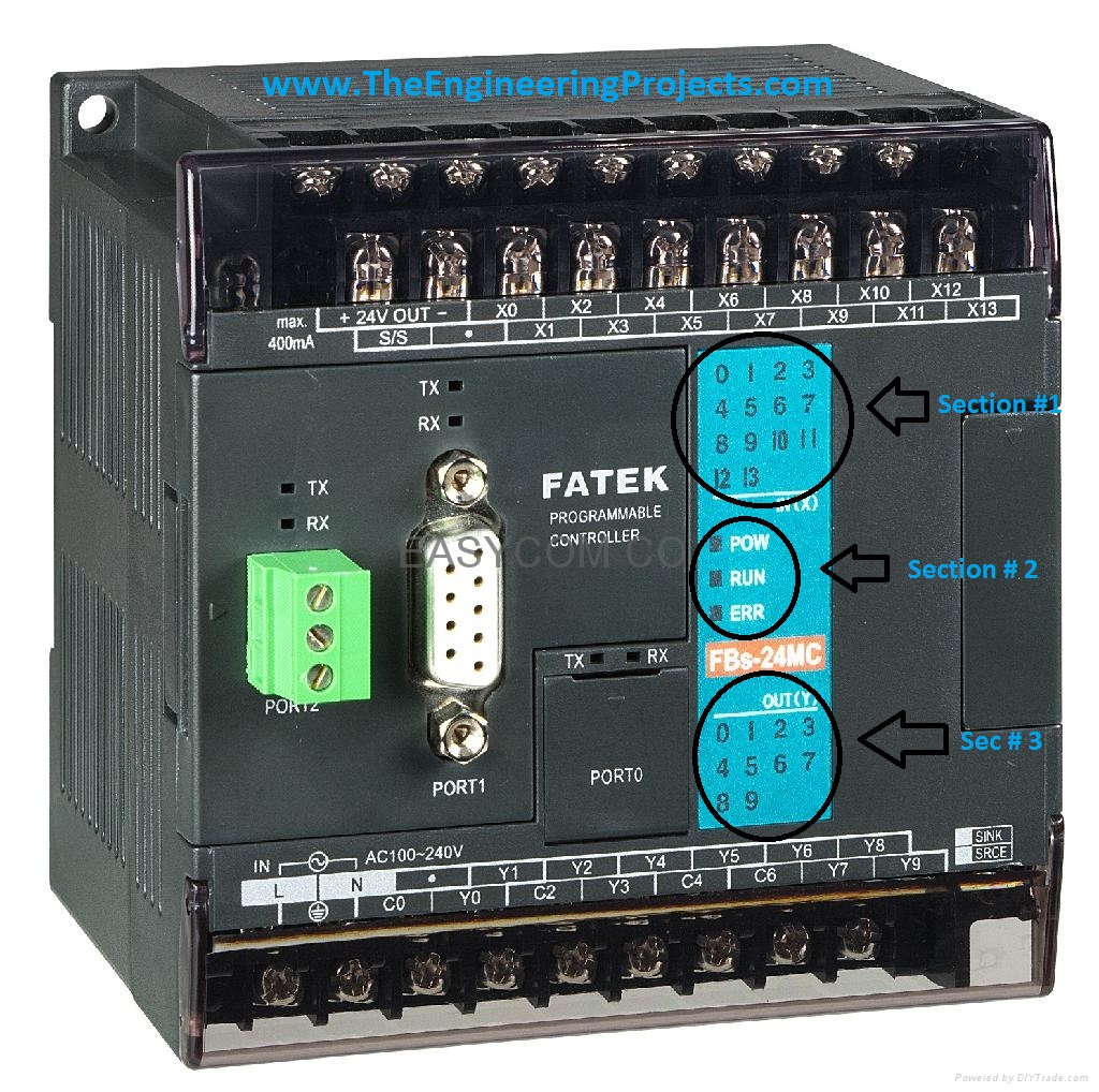
I think now you have the idea about PLC, so now I am getting started with PLC. I am gonna explain the functioning of Fatek PLC as I have used that one but if you are using another model of PC then no need to panic as all PLCs have same functionality. So, it doesn't matter which one you are using. If you check the below image then you will see I have marked three sections in it.
- Section 1 is indicating the status of input pins. If inputs are off then this section will remain as shown in above figure, but if any of the inputs get high, then the respective pin indicator will also glow into red, which indicates that this pin is ON. It helps while you are writing programming code for the PLC.
- Section 2 indicates the status of PLC. If PLC is powered up then the POW led will go red, if you have uploaded the code in PLC and start it then the RUN led will go red and if your code has some error then ERR led will go red.
- Section 3 indicates the status of output pins, it will tell you which output is currently ON.
In the below image, I have indicated Section 4 and 5, these are the input/ output section. If you have a look at it closely then you can see there are two rows of screws, where you plug your wires for inputs and outputs and above them, they are also labelled with white color. So, it goes like that, first row of labelling is for first row of screws and second row is for second row of screws.
- Section 4 is the inputs pins section, so if you check above there are inputs from X0 to X13, which makes it overall 14 inputs. Moreover, there are two pins labelled as + 24V and - 24V, which PLC is providing us, so if you wanna give any input to this PLC you have to make sure that its 24V, otherwise PLC not gonna recognize it.
- Section 5 is the output pins section. and you can see there are total 9 outputs starting from Y0 to Y8, now you are getting confused with C0 to C6. C pins are actually the voltage setter, let me explain, in projects there are different outputs are required like your motor is running at 12V DC while your solenoid valve is running at 220VAC. So, there's a need to set these voltages at the output. Here C pins are used. Suppose you need to give 12V output at Y0 and Y1 then give this 12V at C0 and when Y0 or Y1 is ON then they will give 12V at output. In short, when output gets ON it is actually connecting with their respective C pin.
- Lastly, check the Port 0 in the above image, this is the port where you plug your serial wire inPLC and connect it with your computer in order to upload the programming code.
That's all for today. I hope you got the basic idea of Programmable logic controller and now its time to have a look at Introduction to Ladder Logic for P L C, ladder logic is programming language for PLC. Your feedback are warmly welcome. In the next tutorial, I am gonna cover about ladder logic and will show you how to program a PLC. Till then Take care and have fun.
Tutorial1: Earn with Freebitco.in
Hello friends, hope you all are fine and having fun. Today, I am going to share a new kind of tutorial, which is about online earning. We all know that engineering students are rich with knowledge but they are not much well with earning while studying so I have thought a bit on this issue and finally I decided to share some topics using which one can earn online quite easily. Before going into details, I wanna clear one thing that it won't be that much but still it will be enough to spend a month. So, follow all my tutorials carefully and if you follow them step by step then I am sure that you can earn big. Moreover, you should also have a look at this new Tutorial2: Earn with PrimeDice , its another great site through which you can earn BTC.
So, let's move on to our today's earning trick. First of all, I want you to have a quick look at bitcoin, which is a digital currency and it worth quite a lot. One bitcoin is equal to around 400$ so you can have the idea how much does it cost. So, today I am gonna share a trick using which you can earn really big money but don't need to get rushy because slow and steady wins the race.
Earn with Freebitco.in
- Its a great site from where you can earn bitcoins quite easily and hourly.
- It gives you 0.00000519 BTC every hour, which is quite low but you can earn big from it by playing a game which is Multiply BTC.
- So, first of all, create an account on this freebitco.in site by clicking here.
- After that Claim your free BTC every hour.
- Don't play this game yet as its not worth it.
- Keep on getting free BTC unless you got around 0.00015000 BTC or more.
- Now the real fun begins, now simply click on Multiply BTC game. It will look like as shown in below figure:
- In this game, hit the Auto Bet and then click on ON Lose.
- In ON LOSE, tick the second option which says, increase bet by and make it 100%.
- One more thing to change is BET ODDS, make it 3 instead of 2.
- Now hit the Start Auto Bet button and let the game begin.
- You are gonna win BTC, its a slow process but its free. :)
So, that's all for tutorial one and I hope you got something out of it. I will come with more exciting earning tricks soon.
Introduction to Multilevel Inverters
Hello friends, today's tutorial is about Introduction to multilevel inverters, which is quite a wide field so I am not gonna discuss everything here. I will post more about it in my coming tutorials. Today, I am going to through some light on the multilevel inverter, i.e. how they operate and will also discuss their types in detail. So, let's start it.
An inverter, also named a power inverter, is an electrical power device that is used to convert direct current (DC) into alternating current (AC). Using a few control circuits and switches, one can get AC at any required voltage and frequency. Inverter plays exactly the opposite role of rectifiers as rectifiers are used for converting alternating current (AC) into direct current (DC). There are different types of inverters available these days. You should also have a look at Pure Sine wave Inverter Design with code and Modified Sine Wave Inverter Design with code. I think you are gonna like that one. Few most commonly used inverter types are:
- Square wave inverters
- Modified sine wave inverters
- Multilevel inverters
- Pure sine wave inverters
- Resonant inverters
- Grid-tie inverters
- Synchronous inverters
- Stand-alone inverters
- Solar inverters
We have designed a 3 level Diode Clamped Multilevel Inverter in Simulink MATLAB, which you can buy by clicking on the lower button. As it's mostly used by the engineering students that's why we have placed a very small price of $10 so that they can buy it easily and we also get rewarded for our efforts.
Buy MATLAB Simulink Simulation
Introduction to Multilevel Inverter
- A multilevel inverter is a power electronic device that is capable of providing desired alternating voltage level at the output using multiple lower-level DC voltages as an input.
- Mostly a two-level inverter is used in order to generate the AC voltage from DC voltage.
Now the question arises what’s the need of using a multilevel inverter when we have a two-level inverter. In order to answer this question, first, we need to look at the concept of the multilevel inverter.
Concept of Multilevel Inverter
First, take the case of a two-level inverter. A two-level Inverter creates two different voltages for the load i.e. suppose we are providing Vdc as an input to a two-level inverter then it will provide + Vdc/2 and – Vdc/2 on output. In order to build an AC voltage, these two newly generated voltages are usually switched. For switching mostly PWM is used as shown in Figure 2.1, reference wave is shown in the dashed blue line. Although this method of creating AC is effective but it has few drawbacks as it creates harmonic distortions in the output voltage and also has a high dv/dt as compared to that of a multilevel inverter. Normally this method works but in few applications, it creates problems particularly those where low distortion in the output voltage is required.
PWM voltage output of a two-level inverter
The concept of multilevel Inverter (MLI) is a kind of modification of a two-level inverter. In multilevel inverters we don’t deal with the two-level voltage instead in order to create a smoother stepped output waveform, more than two voltage levels are combined together and the output waveform obtained in this case has lower dv/dt and also lower harmonic distortions. The smoothness of the waveform is proportional to the voltage levels, as we increase the voltage level the waveform becomes smoother but the complexity of the controller circuit and components also increases along with the increased levels. The waveform for the three, five and seven level inverters are shown in the below figure, where we clearly see that as the levels are increasing, the waveform becoming smoother.
A three-level waveform, a _ve-level waveform and a seven-level multilevel waveform, switched at fundamental frequency
Multilevel Inverter Topologies
There are several topologies of multilevel inverters available. The difference lies in the mechanism of switching and the source of input voltage to the multilevel inverters. Three most commonly used multilevel inverter topologies are:
- Cascaded H-bridge multilevel inverters.
- Diode Clamped multilevel inverters.
- Flying Capacitor multilevel inverters.
1. Cascaded H-bridge Multilevel Inverters
This inverter uses several H-bridge inverters connected in series to provide a sinusoidal output voltage. Each cell contains one H-bridge and the output voltage generated by this multilevel inverter is actually the sum of all the voltages generated by each cell i.e. if there are k cells in an H-bridge multilevel inverter then a number of output voltage levels will be 2k+1. This type of inverter has an advantage over the other two as it requires fewer components as compared to the other two types of inverters and so its overall weight and price are also less. Below Figure shows a k level cascaded H-bridge inverter.
One phase of a cascaded H-bridge multilevel inverter
In a single-phase inverter, each phase is connected to a single dc source. Each level generates three voltages which are positive, negative and zero. This can be obtained by connecting the AC source with the DC output and then using different combinations of the four switches. The inverter will remain ON when two switches with opposite positions will remain ON. It will turn OFF when all the inverters switch ON or OFF. To minimize the total harmonic distortion, switching angles are defined and implemented. The calculations for the measurement of switching angle will remain the same. This inventor can be categorized further into the following types:
- 5 levels cascaded H Bridge Multilevel Inverter
- 9 levels cascaded H Bridge Multilevel Inverter
In 5 level cascaded H Bridge Multilevel Inverters, Two H Bridge Inverters are cascaded. It has 5 levels of output and uses 8 switching devices to control whereas in 9 level cascaded H Bridge Multilevel Inverters, Four H Bridge Invertors are cascaded. It has 9 output levels and use and use 16 switching devices.
Applications of Cascaded H-bridge Multilevel Inverters
Cascaded H Bridge Multilevel Inverters are mostly used for static var applications i.e., in renewable resources’ of energy and battery based applications. Cascaded H Bridge Multilevel Inverters can be applied as a delta or wye form. This can be understood by looking at the work done by Peng where he used an electrical system parallel with a Cascade H Bridge. Here inverter is being controlled by regulating the power factor. Best application is when we used as photovoltaic cell or fuel cell. This is the example of Parallel connectivity of the H Bridge Multilevel Inverter.
Example of 3 phase Wye Connection
H Bridge can also be used in car batteries to run the electrical components of the car. Also, this can be used in the electrical braking systems of the vehicles.
Scientists and engineers have also proposed the multiplicative factor on Cascade H Bridge Multilevel. It means that rather than using a dc voltage with the difference in levels, it uses a multiplying factor between different levels of the multilevel i.e., every level is a multiplying factor of the previous one.
Advantages of Cascade H Bridge Multilevel Inverters
- Output voltages levels are doubled the number of sources
- Manufacturing can be done easily and quickly
- Packaging and Layout are modularized.
- Easily controllable with a transformer as shown in the Fig 2.5
- Cheap
Cascaded Inverter with transformer
Disadvantages of Cascade H Bridge Multilevel Inverters
- Every H Bridge needs a separate dc source.
- Limited applications due to a large number of sources.
2. Diode Clamped Multilevel Inverters
Diode clamped multilevel inverters use clamping diodes in order to limit the voltage stress of power devices. It was first proposed in 1981 by Nabae, Takashi and Akagi and it is also known as a neutral point converter. A k level diode clamped inverter needs (2k – 2) switching devices, (k – 1) input voltage source and (k – 1) (k – 2) diodes in order to operate. Vdc is the voltage present across each diode and the switch. Single-phase diode clamped multilevel inverter is shown in the figure below:
One phase of a diode clamped inverter
The concept of diode clamped inverter can better be understood by looking into a three-phase six-level diode clamped inverter. Here the common dc bus is shared by all the phases, use five capacitors and six levels. Each capacitor has a voltage of Vdc and same is the voltage limit of switching devices. One important fact should be noted while considering the diode clamped inverter is that five switches will remain ON at any time. Six level, three-phase dc clamped multilevel inverter is shown in the figure below.
Six level three phase inverter
Outputs of each phase can be understood by the following table. Here reference voltage is the negative Vo. Condition 0 means switch is OFF and vice versa. Output waveforms of six level dc clamped inverter is shown below:
Waveform of Six Level Inverter
Vab is the voltage due to the phase lag b and a voltage.
Applications of Diode Clamped Multilevel Inverters
The most common application of diode clamped multilevel inverter is when a high voltage Dc and Ac transmission lines are interfaced. This can also be used in variable speed control of high power drives. Static variable compensation is also an application of diode clamped multilevel inverters.
Advantages of Diode Clamped Multilevel Inverters
- The capacitance of the capacitors used is low.
- Back-to-back inverters can be used.
- Capacitors are precharged.
- At fundamental frequency, efficiency is high.
Disadvantages of Diode Clamped Multilevel Inverters
- Clamping diodes are increased with the increase of each level.
- The DC level will discharge when control and monitoring are not precise.
3. Flying Capacitor Multilevel Inverters
The configuration of this inverter topology is quite similar to previous one except the difference that here flying capacitors is used in order to limit the voltage instead of diodes. The input DC voltages are divided by the capacitors here. The voltage over each capacitor and each switch is Vdc. A k level flying capacitor inverter with (2k – 2) switches will use (k – 1) number of capacitors in order to operate. The figure below shows a five-level flying capacitor multilevel inverter.
A Flying Capacitor Multilevel Inverter with five voltage levels
If we compare above figures, it shows that the number of switches, main diodes and DC-bus capacitors are same in both the cases. The only difference between the two topologies is that the previous one uses clamping diodes in order to limit the voltage while this topology uses flying capacitors for this purpose, and as capacitors are incapable of blocking the reverse voltage, which diodes do, the number of switches also increases. Voltage on each capacitor is differing from the next as it has a ladder structure. Voltage difference between two back to back capacitors determines the voltage in the output frame.
Advantages of Flying Capacitor Multilevel Inverters
Static var generation is the best application of Capacitor Clamped Multilevel Inverters.
- For balancing capacitors’ voltage levels, phase redundancies are available.
- We can control reactive and real power flow.
Disadvantages of Flying Capacitor Multilevel Inverters
- Voltage control is difficult for all capacitors.
- Complex startup.
- Switching efficiency is poor.
- Capacitors are expensive than diodes.
So, that was all about Multilevel Inverters and their topologies. I hope you guys have understood this concept in detail. Please let me know if you have any questions. Till next tutorial, take care and have fun !!! :)