Introduction to ULN2003
Hello everyone! I hope you will be absolutely fine and having fun. Today, I am going to give you a detailed Introduction to ULN2003. We will also discuss the ULN2003 Datasheet, Pinout, Circuit Diagram & Proteus Simulation. If you have ever controlled any motor (i.e. DC Motor, Stepper Motor etc.) with a microcontroller (i.e. PIC, Arduino etc.), then you must have heard about drivers. Why do we need to use drivers? We use drivers (to control motors) because of two reasons.
- First: Microcontrollers operate at 5V while motors operate at different voltages (5V, 12V, 24V etc.).
- Second: Motors are Inductive loads thus they produce back emf, which may damage your microcontroller permanently (if not handled correctly).
Because of these two reasons, we have to use the driver in between the microcontroller & motor. There are different types of motor drivers available and ULN2003 is one of them. If we check its datasheet, then we can see that ULN2003 can handle up to 50V & 500mA. As its current rating is not that high, so it's used to control small motors. For heavy motors, we normally use relays in between ULN2003 & motor. In this case, the Microcontroller is sending a signal to ULN2003, which then forwards it to relays (connected at output). Remember, the relay is also an inductive load. So, we can control different types of loads with ULN2003 i.e. motor, relay, solenoid, actuator etc. You should also have a look at Relay Interfacing with Microcontroller using ULN2003A.
Now, let's have a look at what's inside ULN2003 in detail:
| Where To Buy? |
|---|
| No. | Components | Distributor | Link To Buy |
| 1 | ULN2003 | Amazon | Buy Now |
ULN2003: Definition
- ULN2003 is a 16 Pin IC, consisting of 7 Darlington pairs (each pair protected with suppression diode) and thus has the capability to handle a maximum of 7 loads(could be inductive).
- In simple words, we have 7 drivers in a single ULN2003 chip and thus can control a maximum of 7 loads.
- Each Darlington pair can handle a maximum 500mA load, while the peak value is 600mA.
- Similarly, the maximum output voltage of each Darlington pair is 50V.
- In the below figure, you can see ULN2003 has 16 Pins, where inputs and their respective outputs are placed in front of each other(for ease of circuit designing).
- Other than I/O Pins, we have Ground Pin where we need to provide 0V & Vcc (Common) Pin.
ULN2003 Datasheet
- Here's the link to download ULN2003 datasheet, must read it once.
- I have also given the link to a reliable source, from where you can buy ULN2003 IC.
Download ULN2003 Datasheet
ULN2003 Pinout
- ULN2003 has 16 pins in total:
- 7 Input pins (Pin # 1 to Pin # 7)
- 7 Output pins (Pin # 10 to Pin # 16)
- 1 Ground pin (Pin # 8)
- 1 COM pin (Pin # 9)
- ULN2003 Pinout is shown in the below figure:
ULN2003 Pin Description
- The functions associated with each pin of ULN2003 along with pin names are shown in the table given below.
ULN2003 Darlington Pair
- ULN2003 consists of 7 identical Darlington pairs.
- A single Darlington pair consists of two bipolar transistors its maximum operating values are 50V & 500mA (peak 600mA).
- These two transistors of the Darlington pair have a common emitter, while their collectors are open.
- Here's the circuit diagram of a single Darlington pair, shown in the below figure:
ULN2003A Free-Wheeling Diodes
- ULN2003A has free-wheeling diodes, which protect from back emf.
- So, if we are using an inductive load (i.e. relays), then we don't need to add extra diodes if we are controlling it with ULN2003A.
- Logic Diagram of ULN2003A is shown in the below figure:
ULN2003 Features
There are a lot of key features associated with the relay driver ULN2003. A few of them are given below:
- 500mA of the rated collector.
- The high output voltage of around 50V.
- Relay driver applications.
- Output clamp diodes.
- Compatible input with popular logic types.
- Some of the key features are also given in the table below for a better understanding of the working conditions of ULN2003.
ULN2003 Applications
The relay circuit driver ULN2003 has a wide range of applications in real life. Some of the major applications associated with ULN2003A are given below.
- Logic buffers.
- Line drivers.
- Relay drivers (for driving different loads).
- Lamp drivers.
- LED display drivers (display devices).
- Motor (stepper and DC brushed motor) drivers.
ULN2003 Proteus Simulation
- I have designed a simulation in Proteus ISIS for LED control using ULN2003.
- The screenshot of the simulation is shown in the figure below.
- As you can see in the above figure that I have connected Logic State at all inputs of ULN2003A and have connected Leds at outputs.
- So, now when I make the Logic State HIGH then the respective LED will also go ON.
- The running form of the above simulation is shown in the figure below.
- If you change the state of the logic state from 0 to 1, the corresponding LED will be turned ON as shown in the above figure.
- You can download the Proteus simulation here by clicking on the button below.
- Just download the .rar file, extract it and enjoy the simulation.
ULN2003 Simulation in Proteus
- Here's the video in which I have shown how to use ULN2003A in Proteus:
So that is all from the tutorial Introduction to ULN2003. I hope you enjoyed this tutorial. If you face any sort of problem regarding anything, you can ask me anytime in the comments without even feeling any kind of hesitation. I will try my level to entertain you and to solve your issues in a better way, if possible. Our entire team is 24/7 here to entertain you and to solve your issues in one way or the other. I will explore different ICs in my later tutorials and will surely share them with all of you as well. So, till then, Take Care :)
Scrolling Text on LCD with Arduino
Hello everyone! hope you all will be fine. In this article I am going to share the knowledge about displaying
Scrolling Text on LCD with Arduino. A Liquid Crystal Display is usually known as
LCD in the market. It is a display unit made up of liquid crystal. When we want to made electronics based projects, we need a device on which we can show the system’s output and the desired messages. There are a lot of such devices which are helpful to display the output messages and the most common is a seven segment display.
Alternate good option is LCD, which are now available in different size having different qualities. 16×2 LCD Module is a most frequently used device for the electronic projects out of all the other types of LCD’s available in the market. 32 ASCII characters can be displayed on it simultaneously in 2 rows i.e. it has a capacity to show 16 characters per row. 20×4 LCD, 128×64 graphical LCD and 2.4 inch TFT Touch screen LCD are also used commonly for the electronic projects now-a-days in the market and as well as in the institutions.
Scrolling Text on LCD with Arduino
In the tutorial
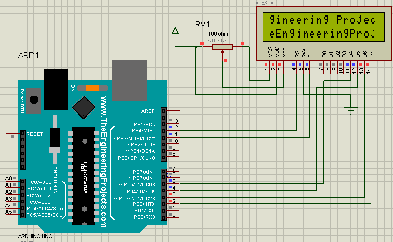
Scrolling Text on LCD with Arduino, we are going to learn how to interface a 16×2 lcd to Arduino UNO and how to display the scrolling text on LCD in Proteus ISIS. First I would like to write a simple code to print something on the LCD and then I will update the previously written code to scroll the text printed already on the LCD.
- You candownload the complete simulation here by clicking on the button below.
Arduino Source Code
- Just download .rar file, extract it and enjoy the complete simulation.
Interfacing 16×2 LCD to Arduino uno
LCD modules are most frequently used devices specially in Arduino based electronic projects. So it is essential to share this tutorial based on interfacing LCD module to Arduino UNO and displaying
scrolling text on LCD with all of you. Interfacing of an Arduino UNO to 16×2 LCD is elaborated in this section. The selected LCD module has 16 pins. You can operate this module in 4 bit mode by using only four data lines (from D4 to D7) or 8 bit mode by using all the eight data lines (from D0 to D7).
In this article we are using the LCD module operating in the 4-bit operational mode i.e. we are using only four data pins. I have divided this tutorial in two parts. First of all, I will explain how to display a simple text messages on the 16×2 LCD with Arduino UNO and secondly I will show that how to display
scrolling text on the same LCD interfaced with Arduino UNO. Before the explanation of this design, let’s have a look at the selected LCD. You should also have a look at this
New LCD Library for Proteus.
Designed Circuit in Proteus ISIS
Find Arduino UNO and a 16×2 LCD in the components library of proteus ISIS ISIS. If arduino library is present in your Arduino software then arduino will be shown in the components library otherwise you have to install Arduino library for proteus ISIS. Wiring diagram of the LCD module with Arduino UNO in proteus ISIS is shown in the figure below. You can download this Proteus Simulation from
Interfacing of LCD with Arduino.
- .Now just copy and paste the given source code in the Arduino software
#include<LiquidCrystal.h> //Library for LCD
LiquidCrystal lcd(12, 11, 5, 4, 3, 2);// LCD pins at which it is attached to the Arduino

void setup() //method used to run the source for the one time onlys
{
  lcd.begin(16, 2);//LCD order i.e. 16 columns & 2 rows
  lcd.print("The Engineering Projects ");//prints on LCD
  lcd.setCursor(0,1);//setting cursor on LCD
  lcd.print("www.TheEngineeringProjects.com");//prints on LCD
  delay(1000);//delay of 1 sec
}
void loop() //method to run the source code repeatedly
{
 lcd.noDisplay();//turn off the display of LCD
 delay(250);//delay to 0.25 seconds
 lcd.display();//turning on the LCD display
 delay(250); //delay of 0.25 seconds again
}
- Now compile the source code and get hex file from it as shown in the figure below.
- Copy this address as shown in the figure above.
- Double click on Arduino UNO in proteus, a new window will be opend as shown in the figure below.
- Paste that address in the file menu as encircled in the figure below.
- Run the proteus simulation from the Arduino software from the upper left corner of the software.
- If everything goes perfect you will see the output as shown in the figure below.
- Copy and paste the source given below in your Arduino software.
#include <LiquidCrystal.h>//Library for LCD
LiquidCrystal lcd(12, 11, 5, 4, 3, 2);//LCD pins at which it is attached to the Arudino

void setup()//method used to run the code for once
{
  lcd.begin(16, 2);//LCD order
  lcd.print("The Engineering Projects ");//prints on LCD
  lcd.setCursor(0,1);//Setting the cursor on LCD
  lcd.print("www.TheEngineeringProjects.com");//prints on LCD
  delay(1000);//delay of 1 second
}

void loop() //used to run the code repeatedly
{
 for(int PositionCount=0;PositionCount<13; PositionCount++)//loop for scrolling the LCD text
  {
    lcd.scrollDisplayLeft();//builtin command to scroll left the text
    delay(150);// delay of 150 msec
    }

   for(int PositionCount=0; PositionCount<29; PositionCount++)
   {
    lcd.scrollDisplayRight(); //builtin command to scroll right the text
    delay(150);//delay of 150 msec
    }
   for(int PositionCount=0; PositionCount<16; PositionCount++)//loop for scrolling the text
   {
    lcd.scrollDisplayLeft();//builtin command to scroll the text left again
    delay(150);//delay of 150 msec
    }
}
- Compile the code given above.
- Obtain the hex file as I told above in the figure.
- And open it in your proteus as I described above.
- Run the simulation like the I have previously done.
- You will be able to see the scrolling text on LCD as shown in the figure below.
- That all from this article to show Scrolling Text on LCD using Arduino.
- Was it difficult? I don't think so :)
So, that is all from the tutorial Scrolling Text on LCD using Arduino. I hope you enjoyed this tutorial. If you face any sort of problem, you can ask me in the comments any time. I will try my level best to solve your issues in a better way, if possible. I will explore Arduino by making different projects on it and will share them with you as well. Till then, take care :)
DC Motor Direction Control in LabVIEW
Hello friends! I hope you all will be absolutely fine and having fun. Today, I am going to share my knowledge with all of you about how to make a simple program for
DC Motor Direction Control in LabVIEW. In my previous tutorials, I have also worked on
DC Motor Direction Control using Arduino. You should go through these tutorials they will be helpful in better understanding of the tutorial DC Motor Direction control using NI LabVIEW. The word DC
is basically an abbreviation of
Direct current. So, a direct current motor is commonly used motor having two input terminals, one is positive and the other one is negative. If we connect these terminals with the voltage supply the motor will rotate. If you change the polarity then motor will rotate in opposite direction. You should also have a look at
Difference between DC & AC Motors to get a better idea about these motors.
DC motor has a lot of applications. You can use it in automation projects, for controlling static as well as mobile robots, in transport system, in pumps,fans,bowers and for industrial use as well. In this tutorial I will work on
DC Motor Direction Control using NI LabVIEW. In my previous tutorial, I have done the
DC Motor Direction Control in MATLAB and I have used the same hardware but instead of controlling it from NI LabVIEW I have controlled it using MATLAB so you must have a look at that tutorial. Now let's get started with DC Motor Direction Control in LabVIEW.
DC Motor Direction Control in LabVIEW
In this tutorial, I will make a simple program to work on the DC Motor Direction Control in LabVIEW. NI LabVIEW is an amazing software tool specially for the students, because it is very easy to use and understand. So, its a student friendly tool. Before going into the details of this tutorial, you must go through my previous tutorials because I am going to use the same hardware setup and same Arduino source code as well. I will made a simple GUI (Graphical User Interface) in LabVIEW for
DC Motor Direction Control in LabVIEW. There will be three different buttons on the GUI for clockwise rotation, counter clockwise rotation and stopping the stepper motor respectively.
- You can download the complete SImulation for DC Motor Direction Control using NI LabVIEW here:
Download LabVIEW Simulation
- Download .rar file, extract it and enjoy the complete simulation for DC Motor Direction Control using NI LabVIEW.
How to Build Complete VI
- First of all open NI LabVIEW software on your laptop or PC so that we could design the GUI for DC Motor Direction Control in LabVIEW.
- Go to the Block Diagram window and Right Click on it.
- Go to Functions-> Instrument I/O-> Serial and you can see different serial blocks like VISA Write, VISA Read, VISA Serial etc.
- Choose the encircled VISA Configure Serial Port and place it on the Block Diagram window.
- VISA Configure Serial Port block will help us to open the Serial Port before executing the algorithm.
- The screen shot of the Block Diagram is shown in the figure below.
- Go to the first input terminal of the VISA Configure Serial Port block and go to Create-> Constant.
- Above step will be helpful to select the COM port of the Arduino board in order to run the program properly.
- Updated Block Diagram window is shown in the figure below.
- Now go to Functions-> Instrument I/O-> Serial, you can see there different serial blocks.
- Choose the encircled VISA Close block and place it on the Block Diagram window.
- The VISA Close block is shown in the figure below and it will be help in closing the Serial Port if needed.
- Now, go to the Functions-> Programming-> Structures and you can see the different structures there like For Loop, While Loop, Case Structure etc.
- Choose the encircled block as shown i the figure below.
- Place all the above blocks in a way shown in the figure below.
- Now, go to the Functions-> Programming-> Structures-> Flat Sequence.
- Flat sequence block is encircled and is shown in the figure below.
- Put your cursor and go to Add Frame After.
- Similarly ad another case after this as shown in the figures below.
- Newly added frame is shown in the figure below.
- Now, go to Functions-> Instrument I/O-> Serial, you can see different serial blocks there.
- Choose the encircled VISA Write Block and place it on the Block diagram window.
- The figure shown below elaborates the above steps.
- Make the connections as shown in the figure below.
- Now, go the Functions-> Programming-> Structures and you can see different types of structures like for loop, while loop, flat sequence etc.
- Choose he encircled block as shown in the figure below.
- Select the Case Structure block and place it on the block diagram window.
- The figure shown below displays the above step.
- Now, go to the input terminal of the write block and go to Create-> Control.
- Change the name of this block to Command box as shown in the figure below.
- The block diagram window is shown in the figure below.
- Now, go to Functions-> Programming-> Structures and you can see different structures blocks there.
- Choose the encircled block as shown in the figure below.
- Select the Local Variable Block and place it on the Front Panel.
- Right click on it and select Command box as shown in the figure below.
- Go to the input terminal of this local variable and go to Create-> Constant.
- Place C inside that constant.
- The figure below elaborates the above step.
- The above case structure is for the clock wise rotation of the stepper motor.
- Similarly make two further case structures for counter clockwise rotation and stopping the rotation of the stepper motor.
- All the three case structures are shown in the figure below.
- You can see three different case structures in above figure.
- The command box variable having command C will rotate the stepper motor in clockwise direction.
- A command box variable having command A will rotate the stepper motor in counter clockwise direction.
- The command box variable having command S will stop the rotation of the stepper motor.
- Now, go to the Front Panel and Right Click on it.
- Go to Controls-> Modern-> Boolean and you can see there different Boolean blocks.
- Choose the encircled block as shown in the figure below.
- Select the Round LED block and place it on the front panel.
- Similarly select two more round LED blocks and place them on the front panel as well.
- Change their names from default to Clockwise, Anti clockwise and Stop Motor.
- All of the above steps are explained visually in the figure shown below.
- The LED shown in the above figure will control the stepper motor on clock wise, counter clock wise direction and will stop the motor as well.
- Now go to the block diagram window and connect these blocks as shown in the figure below.
- At the end, after sending all the commands we must need to close the serial port so that unnecessary exchange of commands could be avoided.
- So I have cleared the all the commands in third frame of the case structure i.e I am sending no commands through the serial port.
- This will be helpful in closing the serial port.
- The figure show below explains all of the above steps visually.
- Now add another case structure to start the program when you want so.
- The figure below shows the newly added case structure.
- Now, go to the Front Panel, the button encircled in the figure shown below is used to start the program when needed.
- Now add a Stop button in order to terminate the program whenever you want so.
- The complete output of the program is shown in the figure below.
- A complete NI LabVIEW Virtual Instrument (VI) is shown in the figure below.
Decorated Front Panel
- Since, I want to make the better external look of the program for DC Motor Direction Control in LabVIEW, so I have decorated a bit.
- The figure shown below shows the decorated Front Panel.
- Go to Controls, Modern-> Decorations you can see different decoration blocks there.
- All these blocks are shown in the figure displayed below.
- I have used three decoration block encircled with the red color, to decorate my program.
- Thick red boundary shows all of the decoration blocks to make your program attractive.
- You can also decorate your programs using this amazing tool.
This is all from the tutorial DC Motor Direction Control in LabVIEW. I hope you all enjoyed this tutorial. If you face any sort of problem in DC Motor Direction Control in LabVIEW, then you can ask me anytime without feeling any kind of hesitation. I will try my level best to solve your issue in a better way if possible. I will explore NI LabVIEW further in my later tutorials. Till then, Take care :)
Stepper Motor Speed Control using Arduino
Hello everyone! I hope you all will be absolutely fine and fun. Today, I am going to tell you that how to make a simple algorithm for
Stepper Motor Speed Control using Arduino. I have already discussed with you about
DC Motor Direction Control using Arduino,
Matlab and NI LabVIEW. Moreover, I have also discussed the
DC Motor Speed Control using Arduino,
Matlab and LabView. If you are working on Stepper Motor, then you must have a look at
Stepper Motor Direction Control using Arduino,
Stepper Motor Direction Control using Matlab and Stepper Motor Direction Control using NI LabVIEW. Now, in this tutorial I will explain you about the program which will helpful for Stepper Motor Speed Control using Arduino. Before going into the details of this tutorial you must have go through my previous tutorials because I am using the same hardware. So, they will be a lot helpful for the better understanding of this tutorial.
In this tutorial I will explain you about making an Arduino program for
Stepper Motor Speed Control using Arduino with the help of the serial communication. If the stepper motor is rotating at its maximum speed and you are continuously sending the command through the serial port to reduce its speed, it s speed will be reduced in proportion to the number of command sent through the serial port. Similarly the same procedure will be followed to increase the speed of the stepper motor.
Stepper Motor Speed Control using Arduino
In the tutorial Stepper Motor Direction Control using Arduino, I will explain you about making an algorithm to run the stepper motor at different speed. If the stepper motor is already running at its maximum speed and you want want to accelerate it further then nothing will happen to the speed of the stepper motor. If the stepper motor is rotating slowly and you enhance its speed, then the speed of the motor will increase in proportion to the number of accelerating command sent through the serial port.
- You can download the complete Arduino source code here by clicking on the button below.
Download Arduino Code
- Download .rar file, extract it and enjoy the complete source code.
Flow Chart
- I have made a flow chart so that you can easily understand the entire algorithm because sometimes it becomes difficult to understand the algorithm with the help of the source code.
- Flow chart for the Stepper Motor Speed Control using Arduino is shown in the figure below.
- First of all we need to start the serial port so that our communication could be started.
- Then there is a method to check the speed, if the speed is greater than the maximum speed of the stepper motor then the program will wait for the next command.
- If the stepper motor is not rotating with its maximum speed then we can increase its speed.
- Similarly if the minimum speed of the stepper motor is reached then the program will rotate for the next commands.
- If the minimum limit of the speed of the stepper motor is not reached then we have a option to reduce its further.
- At the end we should close the serial port so that exchange of unnecessary commands through the serial port could be avoided.
Block Diagram
- Block diagram will be helpful for use for the better understanding of the exchange of information.
- It tells us that how the information is exchanged sequentially among all the components used.
- Block diagram is shown in the figure below.
- Arduino UNO communicates with the L298 motor controller to control the speed of the stepper motor.
- L298 Motor controller manipulates the Arduino's commands and starts to control the speed of the stepper motor.
Arduino Code Description
In this section of the tutorial Stepper Motor Speed Control using Arduino, I am going to elaborate you about the Arduino source.
- I have made two different functions for increasing (accelerating) the speed of the stepper motor and for decreasing (deaccelerating) the speed of the stepper motor respectively.
- I have declared a variable named as count.
- In Accelerate function, you have to send the command H through the serial port to increase the speed of the stepper motor.
- In this function, I am continuously increasing the value of the count i.e as many times you send the command H the speed of the stepper motor will increase continuously.
- The source code of the Accelerate function is given below.
   void Accelerate_Motor()
   {
    count=count+10; //Speed will increase continuously as we continue to press H
    if (count>120)  //Speed must not be greater than 120
    {
      count=120;
      }
    Serial.println("Accelerating"); //printing on the serial port
    Serial.println("");//prints blank line on the serial port
    myStepper.step(stepsPerRevolution);//counter clockwise rotation
    myStepper.setSpeed(count); //Updating the speed of the motor
    lcd.setCursor(3,0);//setting LCD cursor
    lcd.print("Acelerating"); //printing on LCD
   }
- In Deaccelerate function, you have to send the command L through the serial port to increase the speed of the stepper motor.
- In this function, I am continuously reducing the value of the count i.e as many times you send the command L the speed of the stepper motor will reduce continuously.
- The source code of the Deaccelerate function is given below.
void Deaccelerate()
{
  count=count-10; //reducing the speed of the motor
  if (count<20) //speed of the motor must not be less than 20
  {
    count=20;
    }
  Serial.println("Deaccelerating"); // prints on the serial port
  Serial.println(""); //prints blank line on the serial port
  myStepper.step(stepsPerRevolution);
  myStepper.setSpeed(count); //Updating the speed of the motor
  lcd.setCursor(3,0);  //setting cursor on LCD
  lcd.print("Deaccelerating"); //prints the command on LCD
  }
- In the main source inside the loop I am calling both of these Accelerate and Deaccelerate functions.
- The executed commands will also be printed on the LCD (Liquid Crystal Diode).
- The main source code is given below.
#include <LiquidCrystal.h>//Library for LCD
#include <Stepper.h>     //Library for Stepper motor

const int stepsPerRevolution = 255;

// initialize the stepper library on pins
Stepper myStepper(stepsPerRevolution, 4, 5, 6, 7);
char data;
int count = 120;
//LCD pins assigning
LiquidCrystal lcd(8, 9, 10, 11, 12, 13);
void setup() {
  // set the speed at 60 rpm
  myStepper.setSpeed(60);
  // initialize the serial port:
  Serial.begin(9600);// rate at which the arduino communicates

lcd.begin(20, 4);//LCD type

lcd.setCursor(3,0);//setting LCD cursor and printing on it
lcd.print("Stepper Motor");
lcd.setCursor(6,1);
lcd.print("Speed");
lcd.setCursor(5,2);
lcd.print("Control");
lcd.setCursor(2,3);
lcd.print("via Arduino UNO");

delay(3000);

lcd.clear ();//Clearing the LCD screen

lcd.setCursor(0,2);
lcd.print("www.TheEngineering");
lcd.setCursor(4,3);
lcd.print("Projects.com");
}

void loop() {
  if(Serial.available())
  {
    data = Serial.read(); //Reading the data from serial port
  }

    if(data == 'C'){Clockwise();}      //Clockwise rotation
    if(data == 'A'){AntiClockwise();} //Anti-clockwise rotation
    if(data == 'S')                  //stopping the stepper motor
    {
      data = 0;
      lcd.setCursor(3,0);
      lcd.print("No rotation");
      Serial.println("No rotation");//print on the serial
      }
     if(data == 'H'){Accelerate_Motor();}
     if(data == 'L'){Deaccelerate();}
}
Complete Hardware Setup
- In this section of the tutorial, I will show you the complete hardware setup that I have used for this project.
- Hardware consists of 12V power supply, Arduino UNO, L298 motor controller.
- When you upload the code to the Arduino board the system will look like the figure shown below.
- When you press H to increase the speed of the stepper motor, the statement accelerating will be printed on the LCD.
- The printed executed command is printed on the LCD and is shown in the figure below.
- When you press L to reduce the speed of the stepper motor, the statement Deaccelerating will be printed on the LCD.
- The printed executed command is printed on the LCD and is shown in the figure below.
That is all from the tutorial Stepper Motor Speed Control using Arduino. I hope you all have enjoyed this tutorial. If you face any sort of problem regarding anything you can ask me anytime without even feeling any kind of hesitation. I will try my level best to solve your issues in a better way if possible. I will explore Arduino by making further projects and I will share them with all of you as well in my later tutorials. So, till then, Take Care :)
Stepper Motor Direction Control using Arduino
Hello friends! I hope you all will be absolutely fine and having fun. Today, I will elaborate you that how can we make a simple algorithm for
Stepper Motor Direction Control using Arduino. In my previous tutorials I made algorithm for
DC Motor Direction Control using Arduino,
DC Motor Direction Control using Matlab,
DC Motor Speed Control using Arduino and
DC Motor Speed Control using Matlab. Now, in this tutorial I will control a stepper motor using Arduino by entering the different commands through its serial port.
Before going into the detail of this tutorial, you must know the basic difference between stepper and DC motors. DC motors have only two input terminal one is positive and the other one is negative. You just have to provide the power supply and it will start rotating but this is not the case in stepper motor. The stepper motor which I will use in this tutorial, has six pins out of which four pins provide pulses or steps and the other two pins are power pins. So, in this tutorial I will control this six pins stepper motor using L298 motor controller and Arduino UNO board. Basically we can use stepper motor where precision is required. Stepper motor has wide range of applications e.g robotics, CNC machines, home automation etc. In simple word, we can say that stepper motor can be used where there is a need to move at particular angle. So, let's get started with Stepper Motor Direction Control using Arduino:
Stepper Motor Direction Control using Arduino
In this tutorial we will learn how to make a program for
Stepper Motor Direction Control using Arduino by sending dfferent commands from the serial port. First of all, I am going share the list of components used for this mini project.
- Arduino UNO
- Stepper motor (6 wire)
- L298 Motor Controller (H-Bridge)
- Voltage Regulator (7805)
- 1000uF
- Jumper Wires
- Solderig Iron
- Soldering Wire
I want to tell you a bit about the stepper motor because all the other components are discussed in detail in
DC Motor Direction Control using Arduino.
Stepper Motor
Basically, stepper motors are like the DC motors that rotate in discrete steps. They have multiple arranged coils and they are usually known as phases. Motor will rotate one step at a time if we energize each phase sequence. High levels of precision can be achieved by controlling the stepper motor with computer. Steppers motors are available in the market in many different sizes. The speed of the stepper motor is controlled by frequency of pulses generated. They have wide range of applications like hard disk drives, robotics, telescope, antenna, toys etc. A six wire stepper motor is shown in the figure below.
- You can download complete source code for Stepper Motor Direction Control using Arduino by clicking the below button:
Download Arduino Source Code
Selection of Wires
- I have used 6 wire stepper motor and each wire has its own function.
- I have first divided these six wires into two pair.
- Each pair is consisting of three wires out of which one wire is common and the other two generate pulses.
- The two pair of three wires are shown in the figure below.
- Then, I have chosen a common wire in each pair from which the resistance to the other two wires is common.
- I have checked the resistance from the common wire to the both of the other wires of the same pair.
- I found that the resistance from the common wire to both of the other wires is same.
- We can see in the figure above the blue, pink and white wires belong to the same pair out of which white is a common wire.
- Here is the screen shot of the figure when I found the resistance between white and blue wire and I found it to be 8.0 ohms.
- The screen shot of the above steps is shown in the figure below.
- After that. I checked the resistance between white and pink wire and found it to be 8.1 which is almost the same as 8.0 so, this shows that the white wire is common to both of the blue and pink wire.
- Here is the screen shot of the above step.
- Then I found the resistance between pink and blue wire and it was 15.6 which is exactly the double of the earlier resistance.
- It is shown in the figure below.
- I have connect the both common wires as shown in the figure below.
- Here's the video in which I have discussed it in detail How to identify the wires of Stepper Motor:
- The remaining four wires are used to generate pulses which are also know as steps
- I have connected theses four wires to the output pins OUT1, OUT2, OUT3 and OUT4 of the L298 micro controller.
- Input pins of L298 micro controller In1, In2, In3 and In4 are connected to the pin no 7, 6, 5 and 4 of the Arduino UNO's board respectively.
Note:
I have also controlled the stepper motor using PIC micro controller so I would suggest all of you to first go through that tutorial before going into the details of this tutorial.
Block Diagram
- I have made a simple block diagram for Stepper Motor Direction Control using Arduino, which will be helpful to clearly understand the algorithm and the assembling of the components of Stepper Motor Direction Control using Arduino.
- The screenshot of the block diagram is shown in the figure below.
- First of all we need a power supply to run the project properly.
- Arduino reads the commands from the serial port and sends to the L298 motor driver to rotate the stepper motor.
- The commands got printed on the LCD (Liquid Crystal Display).
Arduino Source Code Description
- The main function of the Stepper Motor Direction Control using Arduino is given below.
#include <LiquidCrystal.h>//Library for LCD
#include <Stepper.h> //Library for Stepper motor

const int stepsPerRevolution = 255;

// initialize the stepper library on pins
Stepper myStepper(stepsPerRevolution, 4, 5, 6, 7);
char data;
//LCD pins assigning
LiquidCrystal lcd(8, 9, 10, 11, 12, 13);
void setup() {
  // set the speed at 60 rpm
  myStepper.setSpeed(60);
  // initialize the serial port:
  Serial.begin(9600);

lcd.begin(20, 4);//LCD type

lcd.setCursor(3,0);//setting LCD cursor and printing on it
lcd.print("Stepper Motor");
lcd.setCursor(5,1);
lcd.print("Direction");
lcd.setCursor(5,2);
lcd.print("Control");
lcd.setCursor(2,3);
lcd.print("via Arduino UNO");

delay(3000);

lcd.clear ();//Clearing the LCD screen

lcd.setCursor(0,2);
lcd.print("www.TheEngineering");
lcd.setCursor(4,3);
lcd.print("Projects.com");
}

void loop() {
  if(Serial.available())
  {
    data = Serial.read(); //Reading the data from serial port
  }

    if(data == 'C'){Clockwise();}//Clockwise rotation
    if(data == 'A'){AntiClockwise();}//Anti-clockwise rotation
    if(data == 'S')//stopping the stepper motor
    {
      data = 0;
      lcd.setCursor(3,0);
      lcd.print("No rotation");}

}
- In the code given above we have first initialized the LCD and Stepper motor libraries.
- Then, I assigned stepper motor pins at which it is connected to the Arduino.
- After that I initialized the LCD pins at which it is connected to Arduino UNO.
- Then I have made three different if statements, C for the clockwise, A for the anti clockwise rotation and S for the no rotation.
- Then in the loop I called clock wise and anti clockwise functions whose source code will be give and explained below.
- Then, I cleared the serial data in order to stop the rotation of the motor.
- The source code of the clockwise function is given below.
void Clockwise()//function for clockwise rotation
{
    Serial.println("clockwise"); //printing on the serial port
    Serial.println("");//prints blank line on the serial port
    myStepper.step(stepsPerRevolution);//counter clockwise rotation
    lcd.setCursor(3,0);//setting LCD cursor
    lcd.print("Clockwise"); //printing on LCDa
}
- The source code for the anti clockwise function is given below.
void AntiClockwise()//function for anti clockwise rotation
{
  Serial.println("anti-clockwise");//print on the serial
  Serial.println("");//prints a blank line on the serial
  myStepper.step(-stepsPerRevolution);//clockwise movement
  lcd.setCursor(3,0);//setting LCD cursor
  lcd.print("Anti-clockwise");//printing on LCD
}
- Now, open your Arduino software, just copy and paste the source code given above.
- Run the program and open the Serial Port at the top right of the Arduino software.
- Now, when you enter the command C stepper motor will start running in clockwise direction.
- If you send the command A through the serial port stepper motor will start to rotate in counter clockwise direction.
- If you send the command S the rotation of the stepper motor will be stopped.
Actual Hardware Setup
- The actual hardware operating setup for Stepper Motor Direction Control using Arduino is given in the figure below:
- Now, if you send the command C through the serial port the stepper motor will start to rotate in clockwise direction and the command will also be printed on the LCD.
- The screenshot of the printed command on LCD is shown in the figure below.
- Now, if you send the command A through the serial port the stepper motor will start to rotate in anti clockwise direction and the command will also be printed on the LCD.
- The screenshot of the printed command on LCD is shown in the figure below.
- Now, if you send the command S through the serial port the stepper motor will show no more rotation and the command will also be printed on the LCD.
- The screenshot of the printed command on LCD is shown in the figure below.
- Here's the complete video demonstration of Stepper Motor Direction Control using Arduino, I hope it will help as well:
That's all from the tutorial
Stepper Motor Direction Control using Arduino. I hope you enjoyed this tutorial. If you face any sort of problem, you can ask me anytime without feeling any kind of hesitation. I will try my level best to solve your problem in a better way if possible. I will explore Arduino by making different projects on it. Till then, Take care :)
DC Motor Direction Control using Arduino
Hello friends! I hope you all will be absolutely fine and having fun. Today, I am going to share my knowledge with all of you about how to make a simple program for
DC Motor Direction Control using Arduino. The word DC
is basically an abbreviation of
Direct current. So, a direct current motor is commonly used motor having two input terminals, one is positive and the other one is negative. If we connect these terminals with the voltage supply the motor will rotate. If you change the polarity then motor will rotate in opposite direction. You should also have a look at
Difference between DC & AC Motors to get a better idea about these motors.
DC motor has a lot of applications. You can use it in automation projects, for controlling static as well as mobile robots, in transport system, in pumps,fans,bowers and for industrial use as well. In this tutorial, I will do the
DC Motor Direction Control using Arduino and L298 motor controller. Moreover, I have also used LCD which will give us the status of our DC Motor i.e. whether its moving in clockwise direction or anticlockwise. In my later tutorial I will control the same DC motor using NI LabVIEW 2015 and MATLAB. I have added the next tutorial on this project in which I have done the
DC Motor Direction Control in MATLAB so in that project, I have used the same hardware but instead of controlling it from Arduino I have controled it using MATLAB so you must have a look at that tutorial.
DC Motor Direction Control using Arduino
In this tutorial, I will make a simple program to do the DC Motor Direction Control using Arduino. Arduino is basically an amazing micro controller and is very easy to use because it is an open source device. So, it is a student friendly device. You can also write Arduino programs for different purpose. Arduino is also a cost efficient device in comparison to the other micro-controllers e.g. raspberyy pi, NI-myRIO, galileo, single board RIO etc. First of all I prepared my complete hardware setup. Then I made a program and interfaced it with the hardware. We will discuss all the steps in detail below. The logic is pretty simple i.e. Arduino has to send commands to L298 motor controller and then L298 decides the DC Motor Direction Control by manipulating the Arduino commands. Before going into the detail, I want to show you the list of components required. You can download complete Arduino source file here:
Download Arduino Source Code
Note:
If you are working on DC Motor then you should also have a look at these Proteus Simulations:
Components List & Description
Here's the complete list of the components required for designing DC Motor Direction Control using Arduino:
So, now let's discuss the main components for this project individually so that you get better idea of why these components are used in this DC Motor Direction Control using Arduino:
Arduino UNO
Arduino UNO is basically the back bone of this DC Motor Direction Control Project. It controls and leads the whole project. In this project, Arduino reads the commends from serial port and sends to
L298 motor controller IC in order to control the direction of rotation of the DC motor. So, the Arduino has overall major control over the whole project.
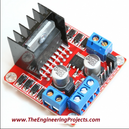
Motor Controller L298
Motor Controller is used to control the direction of DC motor. It consists of an L298 motor driver IC which is capable of rotating the motor in both clockwise and anti clockwise directions by switching its pins from
HIGH to
LOW and vise versa. Moreover, it needs +12V, GND and +5V in order to power it up. So, we will design a voltage regulator which will step down 12V to 5V. So, let's have a look at this voltage driver in next part:
Voltage Regulator
Voltage regulator is also the part of this design. In our daily life, we need to step up or to step down the voltages according to the requirements. Requirements vary with the different purpose. Small electronics components like micro-controller, LED, LCD etc. So the main purpose of voltage regulator is to step down the voltage from 12V to just 5V in order to fulfill the requirements of the electronic components. Step down transformer can also be used instead of voltage regulator. Due to the huge structure and cost we prefer to use voltage regulator.
You should read How to
Design a 5V Power Supply in Proteus to get better idea about this voltage regulator. The circuit diagram of the designed voltage regulator is shown in the figure below.
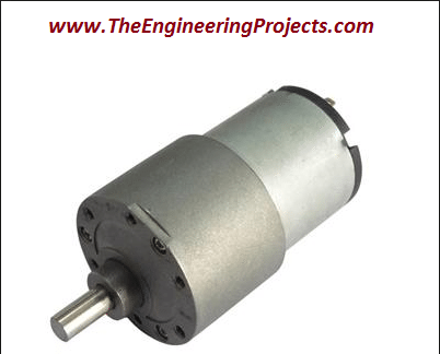
DC Motor
DC motor is the essential part of the different projects and our daily life. for example if we want to automate our house doors i.e if we want to open and close the doors automatically by detecting the person, motor plays a vital role here. Similarly in robotics, vacuum, blowers and air conditioners, DC motor has a wide range of applications.
LED is used here to show whether the designed circuit is working properly or not. Like in mobile phones and laptops as we connect the charger it shows the charging indication. So, we must need some indication that everything is going fine and the circuit is working properly.
Jumper Wires
Jumper wires are used to make the connections between all of the components. Use small pieces of the jumper wires in order to give a better look to the designed circuit. If you are using longer wires for the connections, it will create complexity and causes many problems while operating the circuits.
Power Supply
12V power supply is used as the main power supply. As we know, to operate any of the electronic components or electronic appliances we must need the main power supply. Power supply can vary according to the power consumption of the electronic equipment. Here I am using a 12V DC power supply because it is a small and simple project with minimum power requirements.
LCD 20x4
LCD is used to visualize the commands sent to the serial port. It basially display us that which function is being performed at a particular time. A 20×4 LCD is used and is shown in the figure below. If you haven't worked on LCD before, then you should have a look at
Circuit Designing of LCD with Arduino in Proteus ISIS.
Assembling of the Components
Here are the few steps followed while designing this DC Motor Direction Control using arduino:
- Connect the terminals of the DC motor with the output pins (OUT1 and OUT2) of L298 motor controller.
- Connect L298 motor controller's pin IN1 and IN2 with the Arduino UNO's pin 2 and 5 respectively.
- Now, connect ENA pin of L298 motor controller to the Arduino's pin 9.
- Connect the power supply to turn on the circuit.
- Make sure that you have supplied 12V, 5V and GND properly to the L298 motor controller.
Circuit Diagram
Completely Assembled Diagram
Arduino Code Designing
After making all the connections properly, open your Arduino source code. If you are using Arduino for the first time then you should have a look at
Installation of Arduino Driver in Windows.
- Attach the Arduino board with your PC and go to Search->Device Manager as shown in the figure below.
- Select the device manger and you can see different options here like Batteries, bluetooth radios, keyboards, monitors, ports etc.
- Open the Ports(COM & LPT) as shown in the figure below.
- See the COM Port supported by Arduino Board which COM5 in this case.
- Now open the Arduino software and go to Tools and select the Arduino board and the COM port properly.
- The description is shown in the figure given below.
- Just copy and paste the source code given below.
#include <LiquidCrystal.h>
//Keyboard Controls:
//
// C - Clockwise
// S - Stop
// A - Anti-clockwise

// Declare L298N Controller pins
// Motor 1
int dir1PinA = 2;
int dir2PinA = 5;
int speedPinA = 7; // PWM control
LiquidCrystal lcd(8, 9, 10, 11, 12, 13);

void setup() {

Serial.begin(9600); // baud rate

lcd.begin(20, 4);
lcd.setCursor(5,0);
lcd.print("DC Motor");
lcd.setCursor(5,1);
lcd.print("Direction");
lcd.setCursor(5,2);
lcd.print("Control");
lcd.setCursor(2,3);
lcd.print("via Arduino UNO");
//Define L298N Dual H-Bridge Motor Controller Pins

pinMode(dir1PinA,OUTPUT);
pinMode(dir2PinA,OUTPUT);
pinMode(speedPinA,OUTPUT);

}

void loop() {

// Initialize the Serial interface:

if (Serial.available() > 0) {
int inByte = Serial.read();
int speed; // Local variable

switch (inByte) {

case 'C': // Clockwise rotation
analogWrite(speedPinA, 255);//Sets speed variable via PWM
digitalWrite(dir1PinA, LOW);
digitalWrite(dir2PinA, HIGH);
Serial.println("Clockwise rotation"); // Prints out “Motor 1 Forward” on the serial monitor
Serial.println("   "); // Creates a blank line printed on the serial monitor
lcd.clear();
lcd.setCursor(0,0);
lcd.print("Clockwise rotation");
break;

case 'S': // No rotation
analogWrite(speedPinA, 0); // 0 PWM (Speed)
digitalWrite(dir1PinA, LOW);
digitalWrite(dir2PinA, LOW);
Serial.println("No rotation");
Serial.println("   ");
//lcd.clear();
lcd.setCursor(5,1);
lcd.print("No rotation");
break;

case 'A': // Anti-clockwise rotation
analogWrite(speedPinA, 255); // Maximum PWM (speed)
digitalWrite(dir1PinA, HIGH);
digitalWrite(dir2PinA, LOW);
Serial.println("Anti-clockwise rotation");
Serial.println("   ");
//lcd.clear();
lcd.setCursor(3,2);
lcd.print("Anti-clockwise");
break;

default:
// Turn off the motor if any other key is being pressed
for (int thisPin = 2; thisPin < 11; thisPin++) {
digitalWrite(thisPin, LOW);
}
Serial.println("Wrong key is pressed");
//lcd.clear();
lcd.setCursor(0,3);
lcd.print("Wrong key is pressed");
  }
    }
      }
- Now, upload the source code onto the Arduino UNO board as shown below.
- In the above figure shows that the source code is uploading to the Arduino board.
- Done uploading shows that the source code has been uploaded successfully to the Arduino borad.
- Now, go to the Serial Monitor on the top right corner of the Arduino software.
- Press C, you can see the DC motor is rotating in the clockwise direction and statement Clockwise rotation will be printed on the Serial Monitor.
- Now, press S, the DC motor will stop and a statement No rotation will be print on the Serial Monitor.
- If you want to rotate DC motor in anti-clockwise direction, press A then, the statement Anti-Clockwise rotation will be printed on the Serial Monitor.
- I have made the logic in such a way that if you press any of the other buttons the DC motor will stop in reaction to that and the statement Wrong key is pressed will be printed on the Serial Monitor.
- All of the above steps are shown in the figure shown below.
Final Testing of DC Motor Direction Control using Arduino
- The screenshot of the actual circuitry for DC Motor Direction Control using Arduino is shown in the below figure:
- You can see in the above figure that we have attached Arduino UNO board with L298 Motor Driver and then we have attached DC Motor with Arduino UNO and LCD is used to show the current movement of Motor.
- Moreover we have also designed a small circuit which I have mentioned above and named as Voltage regulator, and it is used to step down 12V into 5V.
So, that's all from the tutorial
DC motor Direction Control using Arduino. I hope you enjoyed this tutorial. In my next tutorials, I will interface this project with LabView and MATLAB. If you face any sort of problem, you can freely ask me
anytime without feeling any kind of hesitation. So, will see you guys in next tutorial. Till then Take care :)
Interfacing of Arduino with GLCD
Hello friends, I hope you all are doing great and having fun with your lives. In today's tutorial, I am going to share How to interface Arduino with GLCD. I am gonna design a Proteus Simulation in which I will interface Arduino GLCD together. GLCD is also called Graphical LCD so today we are gonna do some designing on the LCD. The GLCD I am going to use is ks0108 and its model in Proteus is LGM12641BS1R and I have shared the complete Simulation along with Arduino Code below for download. But I would suggest you to design it on your own so that you could get the most out of it. If you haven't worked on the LCD before then I would suggest you to read
How to Interface Simple LCD with Arduino.
Moreover, I am quite happy to announce that we have started
TEP Forum so if you guys have any questions related to your engineering projects then ask in our forum and we will try our best to resolve your issues. Anyways, let's get back to our today's tutorial and interface Arduino GLCD in Proteus ISIS.
Interfacing of Arduino with GLCD
- First of all, you can download the Proteus Simulation and Arduino Code for Interfacing of Arduino with GLCD, by clicking the below button:
Download Code & Simulation
- Now let's design it so that you can understand how this is working.
- So, first of all design a Proteus Simulation for Interfacing of Arduino with GLCD, as shown in below figure:
Note:
Proteus doesn't have Arduino in its database so you need to install this
Arduino Library for Proteus if you wanna use Arduino in Proteus.
- Now upload the below Arduino code in your Arduino Software and Get your Arduino Hex File, which we are gonna upload in our Proteus Arduino.
- Here's the Arduino Code for Interfacing of Arduino with GLCD:
Note:
- You also have to install the GLCD Library for Arduino, I have added this library in the above package so when you download it first of all install this library in Arduino Software.
#include <glcd.h>
#include "fonts/allFonts.h"
#include "bitmaps/allBitmaps.h"

Image_t icon;

gText textArea;
gText textAreaArray[3];
gText countdownArea =  gText(GLCD.CenterX, GLCD.CenterY, 1, 1, Arial_14);

unsigned long startMillis;
unsigned int  loops = 0;
unsigned int  iter = 0;
         int  theDelay = 20;

void setup()
{
  GLCD.Init();
  if(GLCD.Height >= 64)
    icon = ArduinoIcon64x64;
  else
    icon = ArduinoIcon64x32;

  GLCD.ClearScreen();

  GLCD.SelectFont(System5x7, BLACK);
  GLCD.CursorTo(2, 2);
  GLCD.print("The Engineering");
  GLCD.CursorTo(5, 3);
  GLCD.print("Projects");
}


void  loop()
{

}
- So, now if everything goes fine then when you run your Proteus Simulation of Arduino with GLCD, you will get results as shown in below figure:
- So, what we have done is we just printed our blog name on the GLCD using Arduino.
- Now, in the package you download I have also added another example which when you upload will give you a demo of GLCD.
- Here's the results of the second example, I have added some screenshots:
- So, that's how you can interface Arduino with GLCD and can design anything you want.
- It's really very easy but quite lengthy, I must tell.
- I have designed this video which will help you in better understanding:
So, that's all about Interfacing of Arduino with GLCD and I hope I have helped you guys in some ways. So, will meet you guys in the next tutorial. Till then take care and have fun !!! :)
How to use Arduino PWM Pins
Hello friends, I hope you all are doing great. In today's tutorial, I am going to show you
How to use Arduino PWM Pins. It's the next tutorial in our new
Arduino Tutorial for Beginners series. We will design a small code in which we will be controlling a dc motor's speed using the Arduino PWM Pins but before going into the details, let me first give you an introduction to Arduino PWM Pins because without understanding the PWM, which is the abbreviation of
Pulse Width Modulation, you won't be able to understand How to use Arduino PWM Pins. In our previous tutorial, we have seen
How to use analogWrite in Arduino and I have told you in that tutorial that we use this command for PWM as well. So, today we will have a look at How to do that.
PWM is an abbreviation of Pulse Width Modulation, its a simple technique in which we just modulate the width of a pulse to get our required results. Suppose, we have a 12V DC signal but my requirement is to get the 6V instetad of 12V so here what I need is PWM. I will use PWM on 12V signal and then reduce it to 6V. Another important thing related to PWM is duty cycle. Duty Cycle is the percentage for which the pulse remains HIGH. For example, if the pulse is of 12V and you turn it into 6V using PWM then the duty cycle of PWM is 50%. I have posted many tutorials on PWM for example you should have a look at
How to Generate PWM in 8051 Microcontroller. In this tutorial, I have explained in detail about PWM signal. Moreover, you can also have a look at
DC Motor Speed Control using Arduino in which I have controlled the speed of DC Motor with LDR Sensor. Anyways, let's get back to How to use Arduino PWM Pins:
How to use Arduino PWM Pins ???
- You can download the complete simulation along with its Arduino code for Arduino PWM by clicking the below button:
Download Simulation & Cod
- First of alll, we should know which pins of Arduino can be used for PWM purposes.
- So, if you have a look at the below figure, its an Arduino UNO and all the pins of Arduino UNO which has this sign "~" in front of them are PWM pins.
- If you have a look at the above Arduino UNO image then you can see that "~" this sign is placed in front of six pins.
- So, Arduino UNO PWM Pins are:
- Pin # 3
- Pin # 5
- Pin # 6
- Pin # 9
- Pin # 10
- Pin # 11
- Using these PWM Pins, you can create the PWM pulse which we are gonna do rite now. :)
- So, design a simulation in Proteus as shown in the below figure:
- As you can see in the above figure that I have used LDR Sensor with Arduino UNO and I have plotted the PWM output coming from Arduino UNO on the oscilloscope.
- For PWM output the command used in Arduino is:
analogWrite(PWM_Pin, PWM_Value);
- As, you can see its just an analog Write command and using it you can write any value to the PWM Pin ranging from 0 to 255.
- At 0 the duty cycle of PWM will be 0% and at 255 it will be 100%.
- So, what I did in the above example is I just take the analog value coming from LDR and then transferred it to PWM Pin of Arduino UNO.
- So, now upload the below code in your Arduino board:
int PWMControl= 6;
int PWM_Input = A0;

int PWM_Value = 0;

void setup() {
    pinMode(PWMControl, OUTPUT);
    pinMode(PWM_Input, INPUT);
    Serial.begin(9600);
}

void loop()
{
    PWM_Value = analogRead(PWM_Input);
    PWM_Value = map(PWM_Value, 0, 1023, 0, 255);
    analogWrite(PWMControl, PWM_Value);
}
- So, now Get your Arduino Hex File and upload it in your Proteus software.
- You will also need to download Arduino Library for Proteus, if you wanna use this Arduino UNO in Proteus.
- Now, if everything goes fine then you will get results as shown in below figure:
- Now you can see in the above figure that I have shown the PWM pulse in the oscilloscope and now when you change the LDR value then this pulse's PWM will also change.
- You can download the complete simulation with Arduino code by clicking the button above.
- If you have any problems or issues in this Arduino PWM tutorial then let me know in comments.
I hope you have enjoyed today's post on Arduino PWM Pins and I would suggest you to have a look at
DC Motor Speed Control using Arduino, it will help you a lot in understanding the basic concept of Arduino PWM. So, that's all about Arduino PWM, will see you guys in the next tutorial. Till then take care and have fun !!! :)
Arduino Tutorial for Beginners
Hello friends, I hope you all are fine and having fun with your lives. Today, I am going to share a complete
Arduino Tutorial for Beginners because I was having a lot of requests about it. Reader were asking the same question that they are new to Arduino and how should they start so if you are beginner to Arduino and you don't have any idea How to learn it then you should read the below tutorials.
I have posted all the basic Arduino Tutorial for Beginners already so in today's tutorial I am just gonna arrange them and must ask you to read them one by one from top to bottom and at then end you will really be able to design any kind of project on Arduino. So, let's get started with Arduino Tutorial for Beginners:
Arduino Tutorial for Beginners
Before going into the practical Arduino Programming, you must first read some theoretical knowledge about Arduino which will really help you out in your Arduino Projects. So these are the
basic Arduino tutorial which I will post here step by step:
What is Arduino ?
First of all, you should read this tutorial in which I have given the basic introduction of Arduino. This tutorial is essential one, if you are new to Arduino.
Arduino Vs Raspberry Pi
Next thing you should read is Arduino Vs Raspberry Pi, its not that important but its always good to have a look at alternatives.
Installation of Arduino Driver in Windows
Now, I suppose that you know the basics of Arduino and have got your Arduino UNO in your hand and are ready to install Arduino Drivers in your Windows.
Arduino Library for Proteus
Next thing you need to read is How to use Arduino Library for Proteus. Using this library you can easily simulate your Arduino boards in Proteus software.
Getting Started with Arduino Software
Now you have the basic idea of Arduino board and you know How to use it in Proteus, the next thing you need to do is to have some understanding about Arduino software.
Basic Arduino Commands
Now, that you have understood the basics of Arduino and its programming so now let's have a look at some
Basic Arduino Commands and I would suggest you to test these commands in Proteus on your own so that you do mistakes and get some knowledge from them. Anyways, let's continue with these Basic Arduino Commands:
Getting Started with Arduino Programming
After having a look at the Arduino software, next thing you need to do is to read about Getting Started with Arduino Programming.
Arduino Data Types
Then we have a tutorial at Arduino Data Types in which we have explained in detail all the Data Types of Arduino.
How to use pinMode in Arduino
How to use pinMode in Arduino is the next tutorial which you must read so that you have an idea about how to make pins input or output.
How to use DigitalRead in Arduino
How to use DigitalRead in Arduino is the next tutorial which you must read so that you have an idea about how to use the digital Pins of Arduino.
How to use DigitalWrite in Arduino
How to use DigitalWrite in Arduino is the next tutorial which you must read so that you have an idea about how to use the digital Pins of Arduino.
How to use AnalogRead in Arduino
How to use AnalogRead in Arduino is the next tutorial and I have explained here how to read the status of analog Pins.
How to use AnalogWrite in Arduino
Analog Write is used to update the status of analog Pins as well as PWM Pins. Here we will discuss this command and in next tutorial we will have a look at PWM Pins.
How to use Arduino PWM Pins
How to use DigitalRead in Arduino is the next tutorial which you must read so that you have an idea about how to use the digital Pins of Arduino.
A Simple Arduino LED Example
First of all, you should have a look at A Simple Arduino LED Example in which I have designed a simple example in Proteus and blinked the LED at Pin # 13 of Arduino.
How to write Arduino code
Next article you should have a look at is How to write Arduino code, in this tutorial I have explained how to write arduino code efficiently.
- Now that you have the idea of basic Arduino programming so now let's move a little further and have a look at How to do Arduino Serial Communication. I have posted a lot of Arduino Serial Tutorial and I would suggest you to read them one by one. Here are all the links of Arduino Serial Tutorials:
At the end, I would suggest you to have a look at this list of
Arduino Projects in which I have given all the Arduino Projects which are posted on our blog, so once you get trained in Arduino then you can try those projects and can get pro in Arduino.
How to do Arduino Serial Communication ?
Hello everyone, I hope you all are fine and having fun with your lives. In today's tutorial, I am going to share
How to do Arduino Serial Communication in detail. Recently, I have shared a lot of tutorial on Arduino Serial Communication which contains everything you need for Arduino Serial Communication. So, in today's tutorial, I am actually gonna combine them all and give you a whole picture of How you can easily do the
Arduino Serial Communication. I hope you guys are gonna enjoy this. You should also have a look at
DC Motor Speed Control using Arduino in which I have controlled the DC Motor via Arduino Serial Communication.
I will also share some more tutorials on
Arduino Serial Communication in the near future so I will also add their links in today's tutorial. If you guys have any questions then ask in the comments and we will try our best to resolve your queries. Moreover, most of these codes are testing on Proteus and the simulations are given for download so you can download them from respective link but as a suggestion try to design them on your own. So, let's get started with How to do
Arduino Serial Communication:
How to do Arduino Serial Communication ???
- Arduino boards contain Serial Port in it. If we talk about Arduino UNO then it has the Serial Port at Pin # 0 and Pin # 1 as shown in below figure:
- These are the Arduino UNO Serial Pins and you can see it has only two pins so which means we can add only one serial device with it. We can use software serial, i am gonna discuss that later.
- Now Arduino Mega has four Serial Ports on it as shown in below figure:
- You can see in the above figure that Arduino Mega has:
- Serial: Pin # 0(RX) and Pin # 1(TX).
- Serial1: Pin # 19(RX1) and Pin # 18(TX1).
- Serial2: Pin # 17(RX2) and Pin # 16(TX2).
- Serial3: Pin # 15(RX3) and Pin # 14(TX3).
- So, these are pins through which we can do the Arduino Serial Communication.
- Now let's have a look at them step by step:
1. How to use Arduino Serial Write
- First of all you should read How to use Serial Write in Arduino in which I have explained in detail How to send data through Serial Port.
- In this tutorial I have used Arduino UNO so I have used Pin # 1 which is the TX pin and I am transmitting data Serially.
- For sending data we use below two commands:
Serial.write("a");
Serial.print("b");
- You should read the above tutorial because I have explained everything in it.
2. How to use Arduino Serial Read
- Next tutorial, you need to read is How to use Serial Read in Arduino in which I have explained How you can read data coming through Serial Port and then displayed it on LCD.
- It's an interesting tutorial and you must read that out. It will help you in understanding How you can receive data through serial port and then use that data.
- This data could be coming from GPS or GSM or some other serial sensor or device.
- For reading data though Serial Port you need to use below command:
char data = Serial.read();
- You must read the above tutorial to have a strong grip on it.
3. How to use Arduino Serial Monitor
- Once you got the detailed concept of How to read and write data to Serial Port the next thing you need to do is to read about How to use Serial Monitor in Arduino.
- Arduino Serial Monitor is a great tool needed for Arduino Serial Communication.
- It works as a debugging tool and I have explained in detail in this tutorial How to use it and do your Arduino Serial Communication.
4. How to use Arduino Serial Flush
- Flushing Serial data is important if you wanna do a smooth Serial Communication.
- So, I have posted a tutorial on it in which I have teach How to use Serial Flush in Arduino.
- For Serial Flushing we use the below command:
Serial.Flush();
- Serial Flush is not that necessary when you are working on small projects but if you are doing big projects in which you need to deal with a lot of data like GPS then you must consider it.
5. How to use Arduino Software Serial
- As I have told in the start that Arduino UNO has just one Serial Port so you can only connect one Serial device with Arduino UNO.
- So, what if you want to do more than one serial device with Arduino UNO then there's you need to know How to use Arduino Software Serial.
- So you guys must read this tutorial becuase we have to use it a lot in Arduino Projects.
So, that's all for today. I hope you have enjoyed this tutorial. I am gonna add more tutorial in it when I post them on our blog. So till next tutorial take care and have fun !!! :)