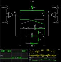
I am designing a pure sinewave inverter, 220V, 50 Hz.
Here is the complete design,
 [img]
[img]http://i.imgur.com/QpX93md.png [/img]
without filter i simulate the whole circuit and tried to plot the current waveform by placing a current probe in RL Load (R = 5 Ohm, L = 16 mH).
I should be getting a sinusoidal current waveform but it is giving my arbitrary result. what might be the problem ?
I have followed this article for PWM generation using Atmega16.
Switching Frequency 16 Khz.
Fundamental Frequency 50 Hz.
http://tahmidmc.blogspot.com/2013/02...mode_2525.html
An external crystal is being used for 16 Mhz clock frequency.
here is the configuration i have done .
 [img]
[img]http://i.imgur.com/JjK5UYJ.png [/img]
Here is the PWM waveform
 [img]
[img]http://i.imgur.com/jPlB2it.png [/img]
 [img]
[img]http://i.imgur.com/cXcdX7y.png [/img]
Instead of IR2110 i have used IR2112, as IR2110 is not available in Proteus. MOSFET Driver circuit is working fine, i have checked the voltage at gate and it is turning it ON/OFF.
MOSFETS are working good.
If i directly filter the PWM signal using RC filter i am getting a sinusoidal voltage waveform.
What might be the problem that i am not getting sinusoidal current waveform ????
If someone interested in debugging my circuit or just wants to run it in their Proteus please tell i will attach the design file.
Here is what i am getting when simulate the circuit
Current waveform
 [img]
[img]http://i.imgur.com/XbKkVQz.png [/img]
Voltage Waveform
 [img]
[img]http://i.imgur.com/rp0XPZp.png [/img]
Any help will be appreciated
I wish tahmid is here to help me out, he is the best guy when it comes to share knowledge and helping out.![]() [img]
[img][/img]
Here is the complete design,
[img]without filter i simulate the whole circuit and tried to plot the current waveform by placing a current probe in RL Load (R = 5 Ohm, L = 16 mH).
I should be getting a sinusoidal current waveform but it is giving my arbitrary result. what might be the problem ?
I have followed this article for PWM generation using Atmega16.
Switching Frequency 16 Khz.
Fundamental Frequency 50 Hz.
An external crystal is being used for 16 Mhz clock frequency.
here is the configuration i have done .
[img]Here is the PWM waveform
[img][img]Instead of IR2110 i have used IR2112, as IR2110 is not available in Proteus. MOSFET Driver circuit is working fine, i have checked the voltage at gate and it is turning it ON/OFF.
MOSFETS are working good.
If i directly filter the PWM signal using RC filter i am getting a sinusoidal voltage waveform.
What might be the problem that i am not getting sinusoidal current waveform ????
If someone interested in debugging my circuit or just wants to run it in their Proteus please tell i will attach the design file.
Here is what i am getting when simulate the circuit
Current waveform
[img]Voltage Waveform
[img]Any help will be appreciated
I wish tahmid is here to help me out, he is the best guy when it comes to share knowledge and helping out.