Introduction to PIC16F88


Introduction to PIC16F88
- PIC16F88 is an 8-bit PIC microcontroller that comes with the enhanced flash processor and nanoWatt technology. It is available in three different packages named PDIP, SSOP, and QFN. First one comes with an 18-pin layout (mostly used) while other two comes in 20 and 28 pin packages respectively.
- The program memory size is 7KB that is used to store the number of instruction on a single chip. While the RAM is 368 bytes and EEPROM comes with memory space around 256 bytes.
- The 10-bit ADC is incorporated on the board that is mainly used to convert the analog signal into a digital one. It plays a vital role to interface sensors, where it gets their signal values in the analog form and convert them to digital ones.

- The crystal oscillator up to maximum value of 20MHz can be interfaced with the chip that is mainly used to generate the clock pulses for the synchronization of the internal operations.
- In terms of carrying out and driving functions that are directly or remotely related to automation, we can not brush off the importance of this module.
1. PIC16F88 Pinout and Description
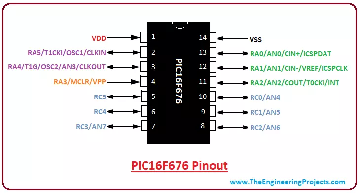
The pinout of any module is very useful to implicate the layout of the module while pin description gives you an overview of what each pin is capable of doing. Let's discuss pinout and pin description one by one.Pinout
The following figure shows the pinout of PIC16F88.
- The PDIP module comes with 18-pin interface while other two SSOP and QFN consist of 20 and 28 pins respectively.
- The former is used for developing individual projects while the other two are used and added in industrial electronic devices.
Pin Description
Following table shows the pin description of each pin and the main function associated with each pin.| Pin# | Pin Name | Pin Description |
|---|---|---|
| 17 | RA0 AN0 | I/O Bidirectional pin Analog pin channel 0 |
| 18 | RA1 AN1 | I/O Bidirectional pin Analog pin channel 1 |
| 1 | RA2 AN2 CVREF VREF- | I/O Bidirectional pin Analog pin channel 2 Comparator Output (VREF) A/D reference voltage input (Low) |
| 2 | RA3 AN3 VREF+ C1OUT | I/O Bidirectional pin Analog pin channel 3 A/D reference voltage input (High) Comparator 1 Output |
| 3 | RA4 AN4 T0CKI C2OUT | I/O Bidirectional pin Analog pin channel 4 Used for clock input to the timer0 Comparator 2 Output |
| 4 | RA5 MCLR VPP | I/O Bidirectional pin This is a master clear low reset pin Programming voltage input |
| 15 | RA6 OSC2 CLKOUT | I/O Bidirectional pin This pin is connected to a crystal oscillator and acts as a crystal oscillator output pin. In RC mode, this pin has a 1/4 frequency of OSC1 |
| 16 | RA7 OSC1 CLKIIN | I/O Bidirectional pin This pin is connected to a crystal oscillator and acts as a crystal oscillator input pin External Clock Source Input |
| 6 | RB0 INT CCP1 | I/O Bidirectional pin External interrupt pin Output for PWM and Compare and Input for Capture |
| 7 | RB1 SDI SDA | All PORTB Pins are software programmed I/O Bidirectional pin SPI data in I2C data |
| 8 | RB2 SDO RX DT | I/O Bidirectional pin SPI data out Receiver Pin Synchronous detect |
| 9 | RB3 PGM CCP1 | I/O Bidirectional pin Programming enable pin for Low-Voltage ICSP™ PWM Output for Compare and PWM, while Input Capture |
| 10 | RB4 SCK SCL | I/O Bidirectional (Interrupt-on-change) pin SPI Synchronous serial clock input/output I2C Synchronous serial clock Input |
| 11 | RB5 SS TX CK | I/O Bidirectional (Interrupt-on-change) pin SPI Slave select Serial transmit pin Synchronous clock |
| 12 | RB6 AN5 PGC T1OSO T1CKI | I/O Bidirectional (Interrupt-on-change) pin Analog pin channel 5 In-Circuit Debugger and programming clock pin. Oscillator output for Timer1 External clock input for Timer1 |
| 13 | RB7 AN6 PGD T1OSI | I/O Bidirectional (Interrupt-on-change) pin Analog pin channel 6 ICSP programming data and In-Circuit Debugger pin Oscillator input for Timer1 |
| 5 | Vss | Ground Pin |
| 14 | Vdd | Voltage Supply Pin |
2. PIC16F88 Features
Features of any device play an important role in order for you to decide and pick the most relevant PIC module for your project. These features differ for different modules available in the market. Before you start working on the project, make sure the features of the device are compatible and resonate with your project requirements and the nature of the final output. Following table shows the complete feature of PIC16F88.| PIC16F88 Features | |
|---|---|
| No. of Pins | 18 (PDIP) |
| CPU | 8-Bit PIC |
| Operating Voltage | 2 to 5.5 V |
| Program Memory | 7K |
| Program Memory Type | Flash |
| RAM | 368 Bytes |
| EEPROM | 256 Bytes |
| ADC Number of ADC Channels | 10-Bit 7 |
| I/O Ports (2) I/O Pins | A, B 16 |
| Packages | 18-pin PDIP 20-pin SSOP 28-pin QFN |
| External Oscillator | up to 20 MHz |
| Timer (3) | 16-Bit Timer (1) 8-Bit Timer (2) |
| Manufacturer | Microchip |
| Comparators | 2 |
| SSP | Yes |
| PWM | 1 (10-Bit) |
| Watchdog Timer | Yes |
| Comparators | 2 |
| Master Clear Reset | Yes |
| In-Circuit Serial Programming | Yes |
| Low Voltage Programming | Yes |
| EEPROM Data Retention | 40 Years |
| Minimum Operating Temperature | -40 C |
| Maximum Operating Temperature | 125 C |
| Technology Used | NanoWatt |
3. PIC16F88 Functions
There are a number of functions associated with this PIC module. Following are the main functions of PIC16F88.Timer
PIC16F88 comes with one 16-bit and two 8-bit timers that can be employed both ways i.e. as a timer as well as a counter. These timers come with internal and external clock select capability. It is important to note that, the timer mode play a role to increment the instruction cycle while the counter mode increments the falling and rising edge of the pin.In-Circuit Serial Programming
In-circuit serial programming (ICSP), also called In-system programming (ISP), is a useful function incorporated in the controller that helps it to program in the installation device, getting it rid to program before making it compatible to the required project.Master Clear Reset (MCLR)
The MCLR, pin 4 in PDIP, calls the external reset for the chip. The reset is executed by keeping this pin LOW. The noise filter is included in the MCLR path that allows to remove and detect the small pulses while the MCLRE configuration bit disables MCLR input. It is worth mentioning here, this MCLR pin is not dependent on the internal resets.USART
The USART module, that stands for Universal Synchronous and Asynchronous Receiver and Transmitter, is added in the device that is mainly used for laying out the serial communication with other devices. Two pins called TX and RX take part for serial communication where former is known as transmitting component that allows transmitting serial data while later is known as receiving a pin, used to receive the serial data.Watchdog Timer
PIC16F88 comes with a built-in watchdog timer that helps in bringing the module in reset position if the program gets stuck in the infinite loop. This timer should be reset to the initial value after every 3 instructions in order to prevent it going to zero value. The watchdog timer is mainly a countdown timer that starts from 1000 and eventually goes down to zero.4. PIC Compiler
- MPLAB C18 Compiler. is a standard compiler used for compiling the code in the controller. You can get this compiler online from the Official Microchip Site.
- These Top 3 PIC C Compilers give you many options to choose from, but MikroC Pro For PIC is mainly used for this purpose, still, it depends on your needs and requirements.
- The code we write in the compiler will generate a hex file which is then transferred to the microcontroller to call and execute the desired instructions.
- There are many unofficial burners available in the market but PICKit3 is mostly preferred and used for the PIC controllers.
5. PIC16F88 Memory Layout and Working
So far you got a hold of pinout, description, features, and compiler used for the controller. In this section, we cover the memory layout that plays a vital role in the execution of the code. The memory of the module stores a number of instruction which can be divided into three major types named: Program Memory (ROM) RAM Memory (Data Memory) EEPROM Memory (Data Memory) Now we discuss each memory one by one and uncover the main features associated with them.Program Memory
The Program memory is used for storing a running program permanently. It is also known as ROM memory or Non-Volatile memory and doesn’t depend on the power supply. The ROM memory is about 7K and is designed using FLASH Technology.Data EEPROM
The EEPROM is a part of data memory and stores running program permanently with one exception i.e. this memory is indirectly mapped out, unlike Program memory that is directly mapped out. The EEPROM contains memory space around 256 bytes and can be accessed and addressed by multiple control registers.Data RAM
RAM memory stores the program temporarily and removes the program once the power supply turns off. It is also known as volatile memory and is classified into two main parts called General-purpose registers (GPR) Special-function registers (SFR) The RAM memory registers are known as data holding places that can hold instruction, storage address, and any kind of data containing the individual character or bit sequence. The data memory can be employed as static RAM and is partitioned into multiple banks. The SRFs registers are mainly used to handle and control the peripherals modules. Following are the main registers available in the RAM memory. STATUS Register. This register is mainly used to switch between the mentioned banks. Setting the fifth bit of this register indicates the performance of bank1 while resetting it will address bank 0. TRISA. This register is used to configure PORTA as an input or output. The value 0 describes it as an input and value 0 shows output. TRISB. This register is similar to TRISA and used for configuring the pins as an input or output for PORTB. W Register. This register is not associated with any register bank and is addressed by the program only. It is a GPR while all other registers described above are SFR. It is important to note that, the required values are written on W register and transferred to the target register before writing them down on the PORTA or PORTB.6. PIC16F88 Block Diagram
Block diagram helps you understand the main functions of the controller and how they work, associate and connect inside the controller body. The following figure shows the block diagram of PIC16F88.
- This PIC module comes with two ports A and B and each port contains 8 pins where higher order bits belong to the STATUS register.
- While CCP1 is dependent on CCPMX bit available in the Configuration Word 1 register.
7. PIC16F88 Projects and Applications
- Student projects for sensor interfacing and motor controlling
- GPS and security systems
- Used in home and industrial automation
- Prototyping custom circuits
- Serial Communication
- Central heating projects
- Embedded system
- Used in starter kits
8. Why Use PIC MicroControllers
- PIC controllers were introduced with the intention to provide easy to use a module and easy to configure interface.
- Gone are days when you have to buy a number of external components for carrying out different operations.
- These controllers have built-in peripherals with a number of functions associated with each pin, getting you rid of buying extra components and make the whole project cheap in cost that covers less space and appears to be lightweight.
- No need to add extra ADC module for converting analog values to digital values, as builtin ADC module incorporated in the tiny chip works best for interfacing different sensors on the board.
- The compiler and burner for the controllers are readily available in the market. Live support is available on the Microchip site where you will get your queries answered sooner than late.
×
![]()