Hello friends, I hope you all are doing great. Today, I am going to share the new 7-Segment Display Library for Proteus. The 7-segment display is the classic way to show numbers: seven bars of light arranged as a figure eight, plus a decimal point. It is on alarm clocks, microwave ovens, fuel pumps, scoreboards, test meters and power supplies, and it is one of the first displays everyone learns to drive with an Arduino.
7-Segment Display Library for Proteus
Latest version: V1.0 (November 2026, this tutorial)
Other component libraries: C945 Transistor · PC817 Optocoupler · Relay Module · Resistor · 5 mm LED · Designer Colour LED · Push Button · Active Buzzer · Electrolytic Capacitor · Ceramic Capacitor · Tantalum Capacitor · Film Capacitor · 1N4007 Diode · Zener Diode · Schottky Diode · Supercapacitor · Photodiode · RGB LED · Bridge Rectifier · Flashing LED · Bi-Colour LED · SMD LED · Slide Switch · Toggle Switch · Rocker Switch · Micro Limit Switch · Emergency Stop Switch · SMD Resistor · Power Resistor · Resistor Network · Potentiometer · Trimmer Potentiometer · Slide Potentiometer · NTC Thermistor · DIP Switch · Fuse · Passive Buzzer · Mini Speaker · LED Bar Graph · IR / UV LED · Small Transistors · TIP122 Darlington · N-MOSFET · P-MOSFET · PC817 Optocoupler · Filament Bulb · Power LED · Voltage Regulator · SCR and TRIAC · Inductor · Toroid Inductor · Crystal
Helping Tools
- Serial Monitor Advance: a serial terminal window for the UART of your board
- Serial Monitor Expert: the serial monitor with extra debugging tools
- LCD Library for Proteus V3.0: 16x2, 20x4 and I2C LCDs to show your readings
Our library has the two sizes you will reach for most often, at true scale: a 0.56 inch single digit and a 0.56 inch four digit display, both with a black face and diffused segments. Each can be common cathode or common anode, in red, green, yellow, blue or white. Every segment is a real LED in the simulation, with its own forward voltage and current, so the segments light as brightly as the eye would see them, even when they are multiplexed. The pop-up reads the display back as characters, times the multiplexing and checks every rating. The demo is a stopwatch with a lap counter, both displays driven from one shared segment bus.
NOTICE: Our team has put a lot of effort into these small parts: the bodies, the animation and the pop-ups are all our own design, and you get them free. Your feedback is the fuel that keeps us going, so please tell us what you think in the comments below or in the 7-Segment Display board of our forum. And if our free libraries help you, you can buy us a coffee. So, let's get started with the 7-Segment Display Library for Proteus:
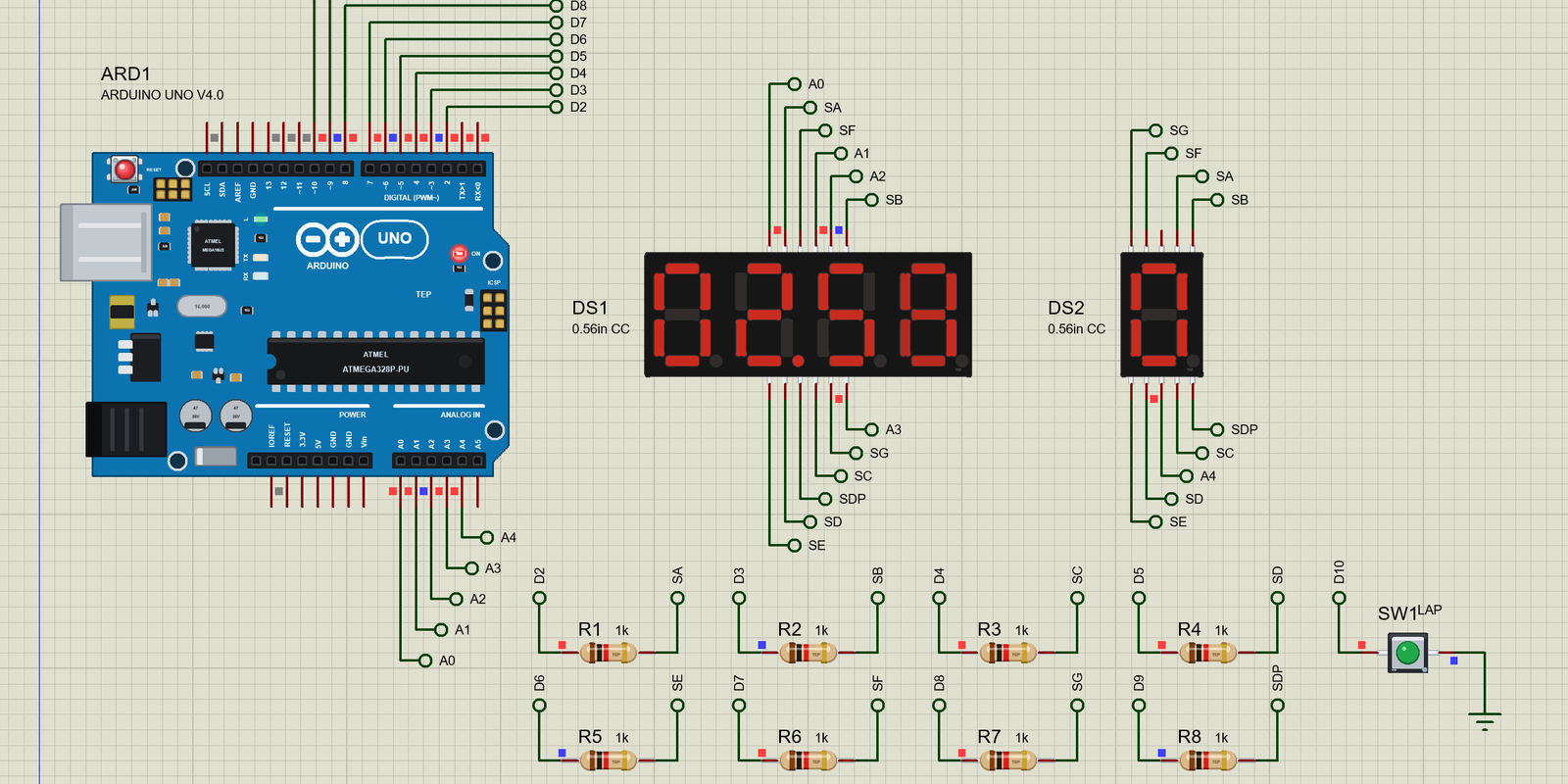
What is a 7-Segment Display?
A 7-segment display is a set of LEDs shaped as bars and arranged in a figure eight. The segments are named with letters: a along the top, then b and c down the right side, d along the bottom, e and f up the left side, and g across the middle. A small round LED, dp, is the decimal point. Light a chosen set and you get a digit: a, b and c make a 7; all seven make an 8; a, b, g, e and d make a 2.
Each segment is an ordinary LED inside the plastic, behind a diffuser that spreads its light over the whole bar. That means each segment needs what any LED needs: a forward voltage, about 2 V for red, and a current limited by a resistor, usually a few milliamps up to 20 mA.
| Feature | The single digit | The four digit |
|---|---|---|
| Digit height | 0.56 inch, 14.2 mm | 0.56 inch, 14.2 mm |
| Body | 12.5 x 19 mm | 50.4 x 19 mm |
| Pins | 10 | 12 |
| Pinout | the SC56-11 layout | the 5641AS layout |
| Commons | COM and COM2, joined inside | D1 to D4, one per digit |
| In the library | SEVENSEG1TEP | SEVENSEG4TEP |
Common Cathode and Common Anode
Inside a single digit, eight LEDs share one connection. In a common cathode display, all their cathodes are joined to the common pin; you connect it to ground, or to a pin set LOW, and a segment lights when its own pin goes HIGH. In a common anode display, the anodes are joined; the common goes to the supply, or a pin set HIGH, and a segment lights when its pin goes LOW. The two look identical, so the part number, and our COMMON property, tells you which you have. Wire one as the other and nothing lights at all.
The Pinout
The pins follow the usual layout of each size. On the single digit, the bottom row from the left is e, d, COM, c and dp, and the top row from the right is b, a, COM, f and g. On the four digit display, the eight segment pins are shared by all four digits, and each digit has its own common, D1 to D4.
| Pin | Single digit | Four digit |
|---|---|---|
| 1, 2, 3 | e, d, COM | e, d, dp |
| 4, 5, 6 | c, dp, b | c, g, D4 |
| 7, 8, 9 | a, COM2, f | b, D3, D2 |
| 10, 11, 12 | g | f, a, D1 |
Multiplexing
A four digit display has only 12 pins for 32 LEDs, because the segment pins are shared. If you light one digit's common and set the segment pins for that digit, only that digit shows the pattern. So the trick is multiplexing: light one digit at a time, very quickly, round and round. Each digit is only on for a quarter of the time, but if every digit comes round more than about 60 times a second, the eye blends it all into a steady display of four digits.
The same trick can stretch further. In our demo, the single digit display shares the same eight segment lines as the four digit one, and simply becomes the fifth digit in the round. Thirteen Arduino pins drive 40 LEDs.
Resistors and Currents
Put one resistor on each segment line, never one on the common. A single resistor on the common would share its current among however many segments are lit, so an 8 would be much dimmer than a 1. With one resistor per segment, each lit segment gets the same current whatever the digit.
The common pin is the one to watch. It carries the current of every lit segment of its digit at once: eight segments at 10 mA each would be 80 mA, twice what an Arduino pin can give. There are two ways out. Use larger resistors so that eight segments together stay under the pin's limit, which is what our demo does with 1 k, or drive each common through a transistor and use smaller resistors for a brighter display.
Brightness and the Eye
A multiplexed segment is pulsed: on for its digit's turn, off for the others. The eye does not see the pulses, only their average. So a segment that takes 3 mA for a fifth of the time looks like a segment taking 0.6 mA steadily. The eye's response is roughly logarithmic, so that still looks clearly lit, though dimmer than a segment at 10 mA. Our model does exactly this: it averages each segment's current over 20 ms, about the time the eye takes, and lights it on a log scale.
Reading It Back
Since the model knows which segments of each digit were lit in that digit's last turn, it can turn them back into characters: 0 to 9, A to F, a minus sign and a few letters. The pop-up shows what the display reads, and the event log records it. It reads a whole frame at a time, taken just as the first digit's next turn begins, so a reading is never half old and half new.
Where They Are Used
7-segment displays show the time on clocks and timers, the setting on ovens and washing machines, the reading on meters, thermometers and scales, the score on scoreboards and the price on fuel pumps. They are bright, easy to read from across a room and cheap, which is why they are still everywhere decades after they first appeared.
Features of the 7-Segment Display Library for Proteus
- The real look, at true scale: 0.56 inch single and four digit displays with a black face and diffused segments, and our small TEP signature.
- Every segment is an LED: its own forward voltage and current, stamped like any LED junction.
- Lit as the eye sees it: a 20 ms average on a log scale, right for steady and multiplexed drive.
- Common cathode or anode, five colours: one property each.
- It reads itself back: the digits as characters, a whole frame at a time.
- It times the multiplexing: the refresh rate and each digit's share of the time.
- A pop-up for each display: the reading, the display drawn large, a bar for every segment line and common, graphs, an event log and a check page.
- A complete package: about 1.9 MB with the library, our Arduino UNO V4.0, our resistors and push button and the demo, without the source code of the model.
The 7-Segment Displays in Proteus
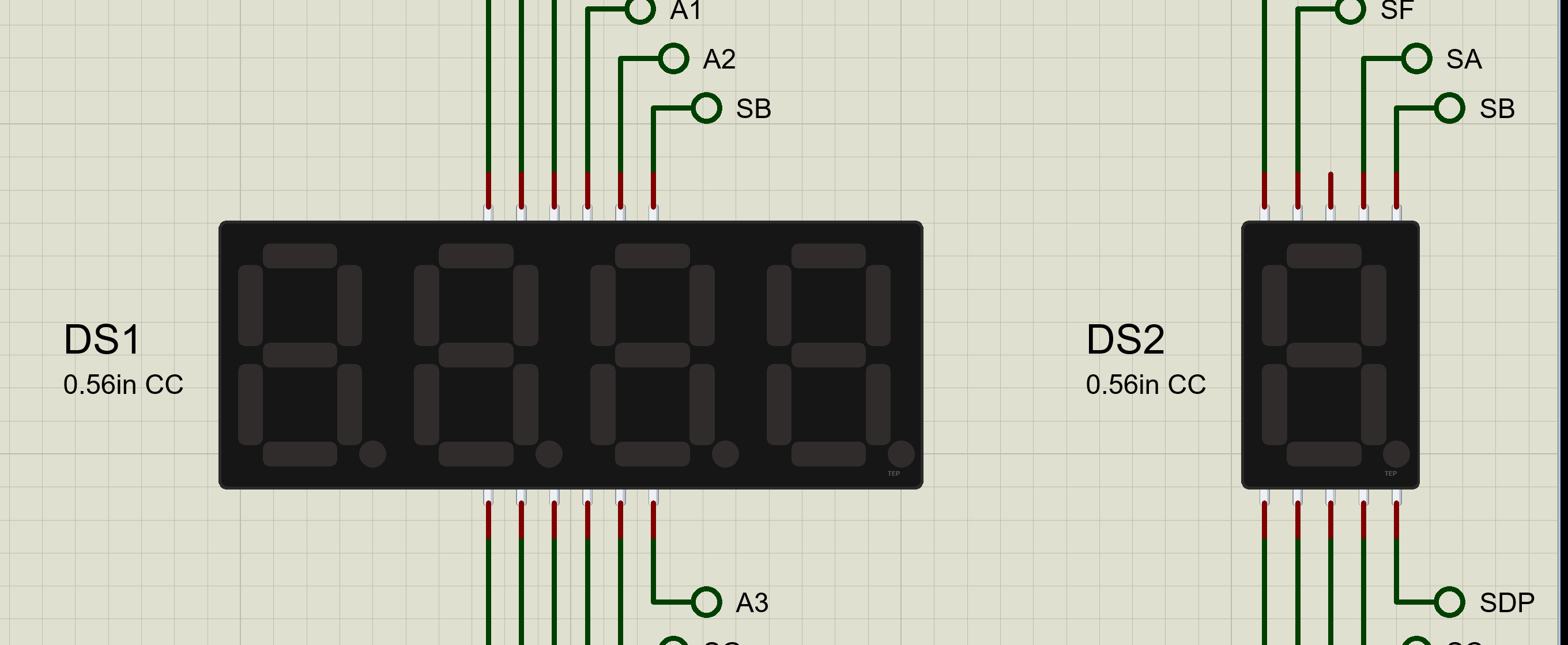
The devices are SEVENSEG1TEP and SEVENSEG4TEP in TEPSEVENSEG.LIB, under Optoelectronics, 7-Segment Displays, with the prefix DS and the model TEPSEVENSEG.DLL. Search SEVENSEG in Pick Devices. The pins come out of the top and bottom edges in the order of the real parts, and are named after their segment or common.
The Properties
| Property | What it does |
|---|---|
| Common | CATHODE or ANODE |
| Colour | RED, GREEN, YELLOW, BLUE or WHITE: Vf 2.0, 2.2, 2.1, 3.2 or 3.1 V at 20 mA |
Download 7-Segment Display Library for Proteus
Click the button below to download 7-Segment-Display-Library-for-Proteus-v1.0.zip (about 1.9 MB, without the source code of the models):
7-Segment Display Library for Proteus V1.0- README.txt: installation, the demo, the properties, the pinouts, troubleshooting and the limits.
- Proteus Library Files:
TEPSEVENSEG.LIB,TEPRESISTOR.LIB,TEPBUTTON.LIBand ourArduinoV4TEP.LIB. - Proteus Model Files:
TEPSEVENSEG.DLL,TEPRESISTOR.DLL,TEPBUTTON.DLLandTEPARDUINO.DLL. - Arduino Code: the demo sketch.
- Proteus Simulation: the demo project, its HEX file and copies of the DLLs.
No Proteus yet? Read How to Download and Install Proteus 7 and 8. New to libraries? Follow How to Install a New Library in Proteus.
How to Install 7-Segment Display Library for Proteus
- Close Proteus and extract the whole zip file, for example to your Desktop.
- Copy the files from Proteus Library Files into the LIBRARY folder of Proteus.
- Copy the files from Proteus Model Files into the MODELS folder.
- Delete
TEPSEVENSEG.IDXfrom the LIBRARY folder if it is there. - Start Proteus, press P and search for SEVENSEG.
Demo: A Multiplexed Stopwatch
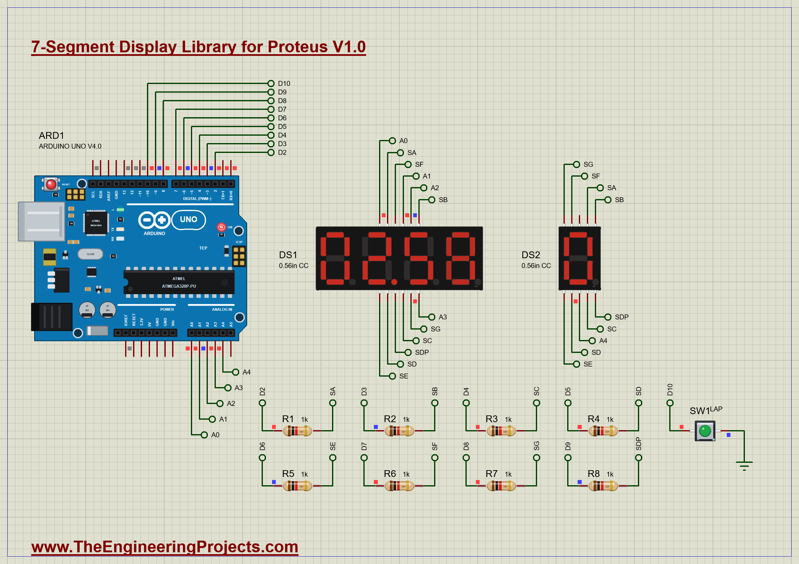
Eight 1 k resistors, R1 to R8, connect D2 to D9 to a segment bus, SA to SG and SDP, shared by both displays. DS1, the four digit display, has its commons D1 to D4 on A0 to A3 and shows a stopwatch: seconds and hundredths, 00.00 to 99.99. DS2, the single digit display, has its common on A4 and shows the lap count. SW1, a push button from D10 to ground, counts a lap. Open Seven-Segment-Stopwatch-ArduinoUnoV4.pdsprj. It runs on our Arduino UNO Library for Proteus V4.0, with its built-in monitor, the same window as our TEP Serial Monitor Advance for Proteus. The resistors are from our Resistor Library for Proteus, the button from our Push Button Library for Proteus.
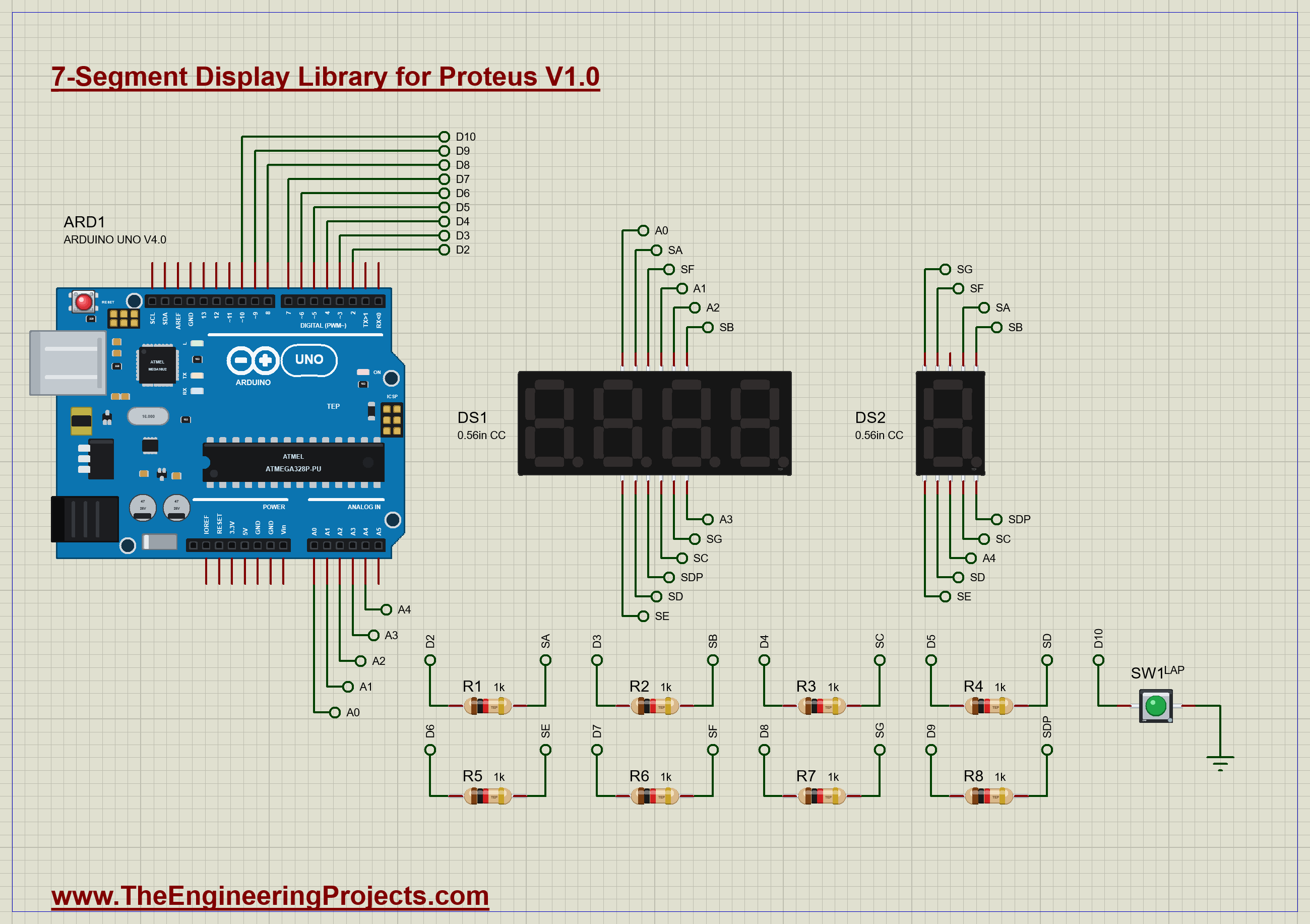
| Part | Connection | Job |
|---|---|---|
| R1 .. R8 (1 k) | D2 .. D9 to SA .. SG, SDP | one resistor per segment line |
| DS1 (4 digits) | segments on the bus, D1 .. D4 on A0 .. A3 | the stopwatch |
| DS2 (1 digit) | segments on the bus, COM on A4 | the lap count |
| SW1 (push button) | D10 to GND | a lap |
The Sketch
The digits are stored as bit patterns, bit 0 for segment a up to bit 6 for g:
const byte DIGIT[10] = {0x3F, 0x06, 0x5B, 0x4F, 0x66, 0x6D, 0x7D, 0x07, 0x7F, 0x6F}; // bit 0 = a ... bit 6 = gEvery 2 ms the sketch moves on to the next of the five digits. It switches all the commons off first, sets the segment pins for the new digit, then switches that digit's common on, so no digit ever shows another digit's pattern:
void showSlot(byte k) {
  for (byte d = 0; d < 5; d++) digitalWrite(COM_PINS[d], HIGH);   // every digit off
  for (byte s = 0; s < 8; s++) digitalWrite(SEG_PINS[s], bitRead(frame[k], s));
  digitalWrite(COM_PINS[k], LOW);                                  // this digit on
}
Five digits at 2 ms each make a 10 ms frame. The sketch works out the new digits only at the start of a frame, so a frame never mixes an old value with a new one:
if (slot == 0) { // a new frame: all five digits from one moment, never half old, half newThe lap button is read in the same loop, with a 200 ms lock-out against bounce, and each lap is printed with its time.
Run the Demo
Press Run. The stopwatch starts at once. On the sheet, the segments light in red, the hundredths digit a blur as it changes a hundred times a second, just as on a real display. We paused at 2.65 s of the run:
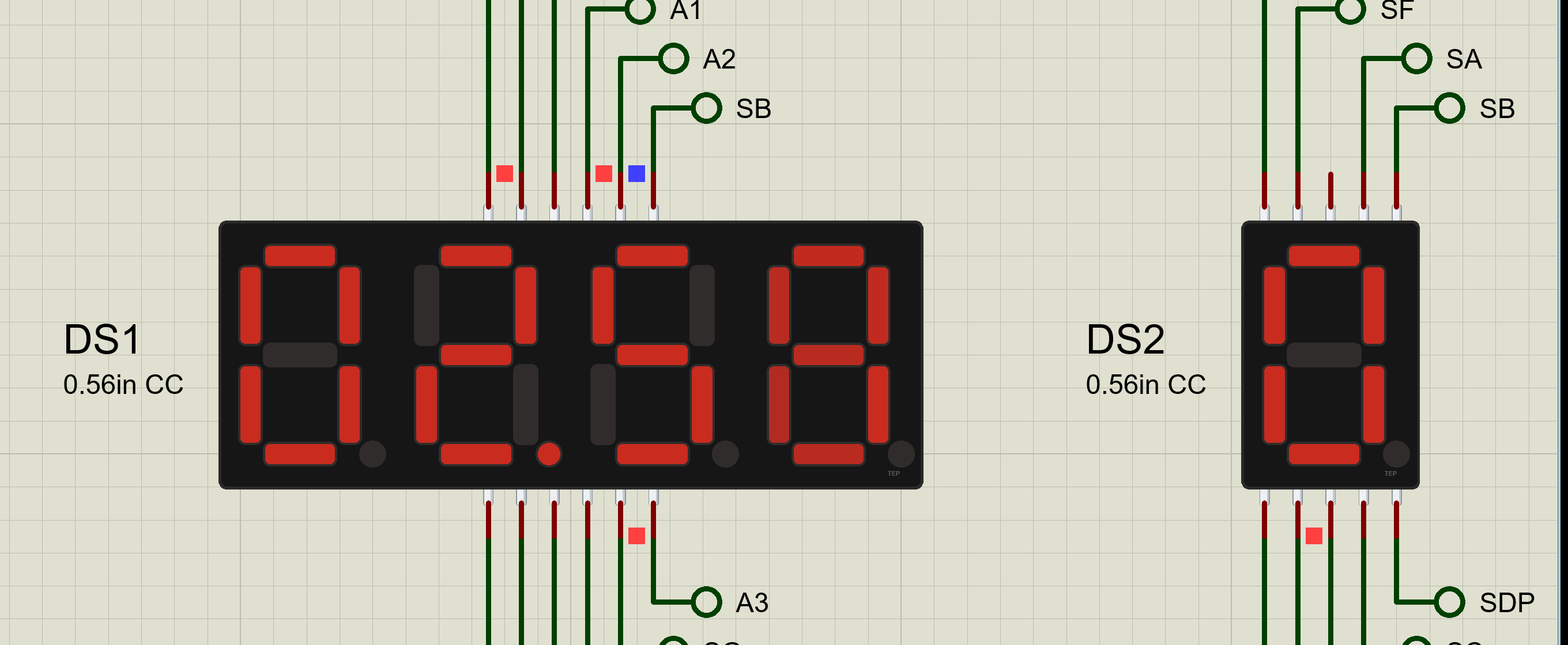
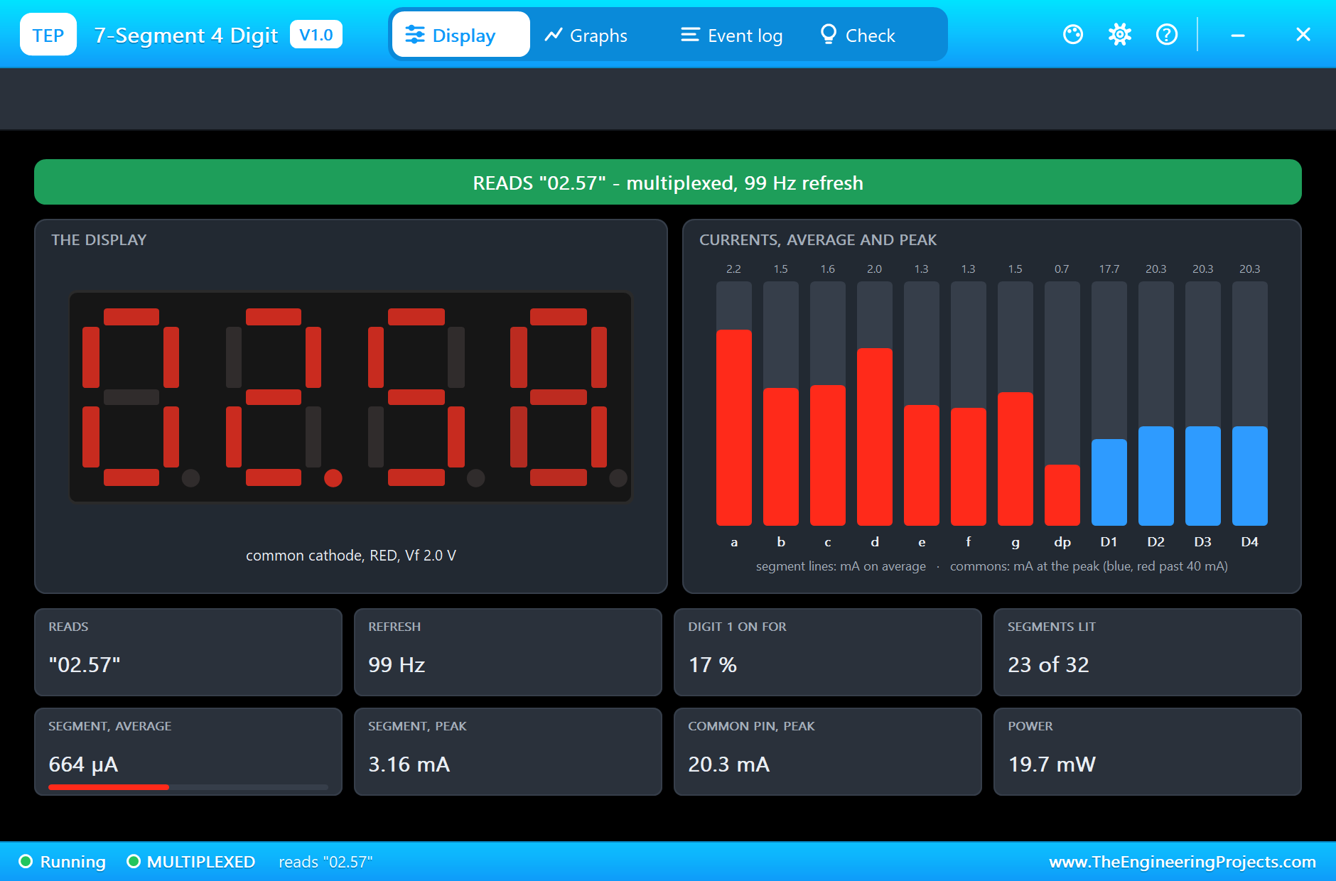
Click the small dot on DS1 to open its pop-up. It reads "02.56", the stopwatch a few hundredths behind the run while the sketch starts up. The refresh is 99 Hz, and each digit is on for about a fifth of the time. The bars show the average current on each of the eight segment lines and the peak on each common: 20.3 mA at the most, comfortably under the UNO pin's 40 mA:
Here is the complete circuit, truly running:
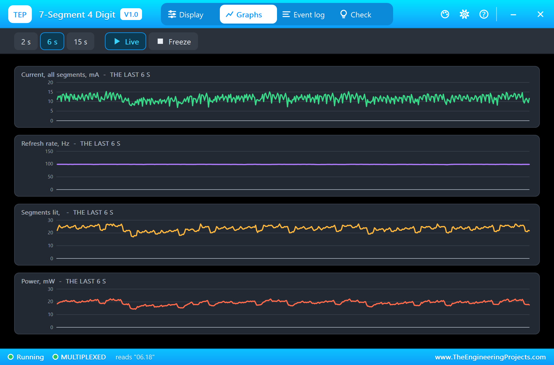
The Graphs page shows the total current, the refresh rate holding at about 99 Hz, the number of segments lit as the digits change, and the power, about 20 mW for the four digits together:
Counting Laps
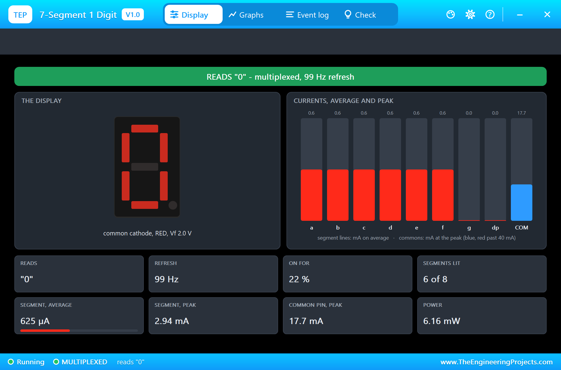
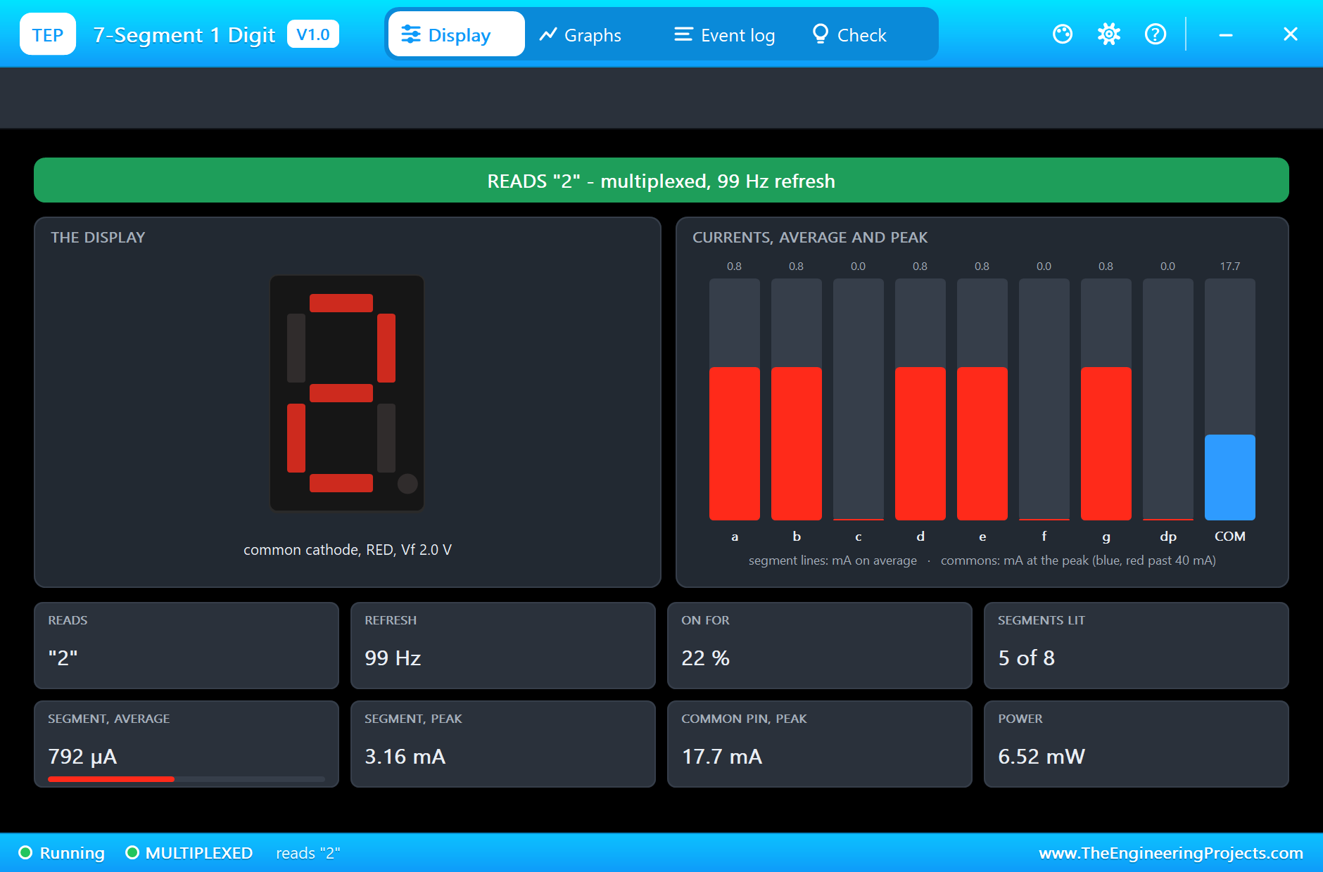
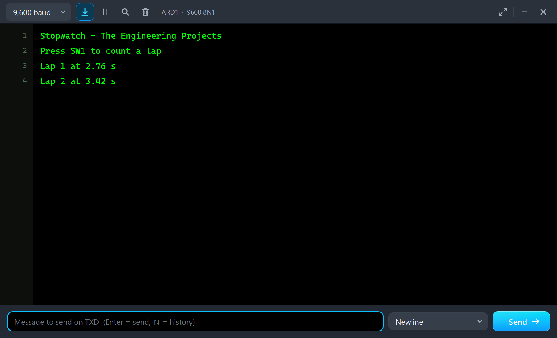
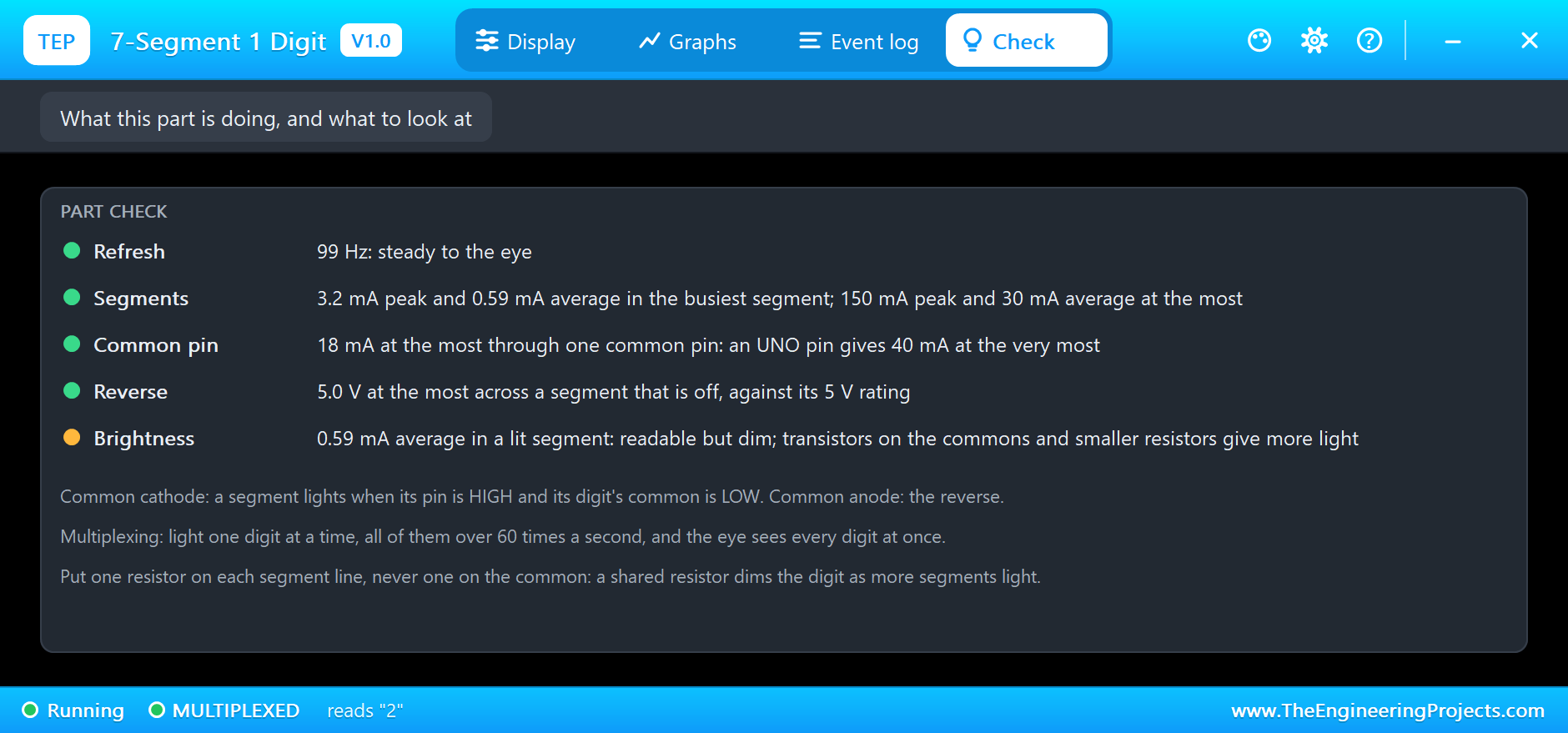
Now press SW1 twice. DS2 counts 1, then 2, and the monitor prints the time of each lap. Its pop-up reads "2": segments a, b, g, e and d lit, 0.8 mA on average each:
The Log and the Check Page
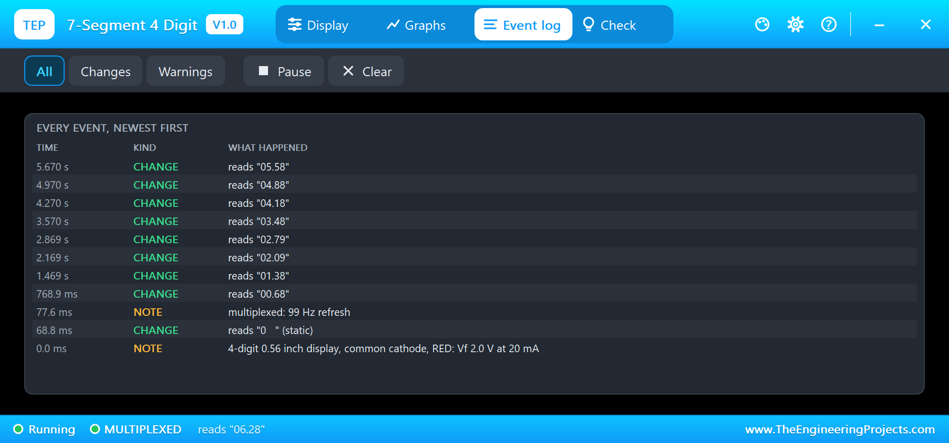
The Event log records what DS1 reads every 0.7 s: 00.68, 01.38, 02.09, 02.79 and on, the stopwatch read back from its own segments:
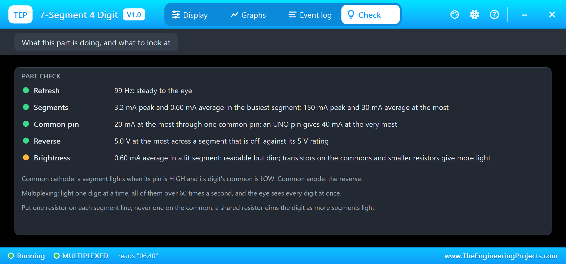
The Check page judges the refresh, 99 Hz and steady to the eye, the segments, 3.2 mA peak and 0.6 mA average, the commons, 20 mA at the most, and the reverse voltage on the segments that are off, 5.0 V, right at their rating. It marks the brightness amber: readable but dim. For a brighter display, drive the commons with transistors and use smaller resistors:
Try It Yourself
- Make the slots 10 ms instead of 2 ms, and watch the refresh drop and the Check page warn of flicker.
- Change both displays to COMMON ANODE, and swap HIGH and LOW for both the commons and the segments in the sketch.
- Try GREEN or BLUE, and see the forward voltage change on the pop-up.
- Lower the resistors to 220 ohm, and watch the common pin go past 40 mA.
- Show a temperature or a counter instead of the stopwatch.
Ideas to Extend the Demo
- Add a start and stop button to the stopwatch.
- Drive the commons with transistors and use 220 ohm resistors for a bright display.
- Show minutes and seconds with the decimal point as a separator.
- Use a shift register to drive the segments from three pins.
Your Own Sketches
The demo sketch is in the zip file, and you can change it in the Arduino IDE. New to Arduino? Start with our Arduino Tutorial for Beginners. Export the compiled binary, and set the UNO's PROGRAM property to the new file. Our guide on How to get the HEX file from Arduino shows you where the file ends up.
Things to Know Before Using a Real 7-Segment Display
- Check the type: common cathode and common anode look the same; the part number tells.
- One resistor per segment line: never a single resistor on the common.
- Watch the common pin: it carries every lit segment of its digit.
- Multiplex fast enough: every digit over 60 times a second.
- Update at the start of a frame: so a digit never shows half an old value.
Troubleshooting
- Nothing lights: the common is the wrong type, or it is never driven to its active level.
- Wrong segments light: the segment order on the pins; check the pin table.
- The digits flicker: the refresh is under 60 Hz; shorten the slots.
- Ghost segments: the commons switch before the segments; turn all digits off first, then set the segments.
- The part is not simulated:
TEPSEVENSEG.DLLis missing from MODELS and from the project folder.
Limitations of the Simulation
- The colour shift of an LED with its current is left out.
- The junction's heating and slow drift are not simulated.
- The segments are drawn upright; many real displays lean slightly.
- Arduino is a name of Arduino; this library is not made or endorsed by Arduino or Labcenter.
- Tested in Proteus 8.5 in November 2026 (the demo as shipped). Proteus 7 is not supported.
So, that was all about the 7-Segment Display Library for Proteus. I hope it helps you build clocks, counters and meters, and see exactly how multiplexing works before you build it on a board. If you have any questions, ask in the comments and I will help you out. Till the next tutorial, take care and have fun!