Hello friends, I hope you all are doing great. Today, I am going to share the new Air-Core Gauge Library for Proteus V1.0. Look behind the tachometer, the speedometer or the fuel gauge of a car from the last forty years and you will very likely find an air-core movement: a small plastic cube with two coils wound across each other and a magnet inside that carries the needle. It has no gears and no spring, it can point anywhere round the full circle, and makers love it for home-built dashboards, sim-racing clusters and retro gauges driven by an Arduino.
Air-Core Gauge Library for Proteus
Latest version: V1.0 (November 2026, this tutorial)
Other motors: SG90 Servo · TT Gear Motor · 28BYJ-48 Stepper · NEMA 17 Stepper · MG996R Servo · N20 Encoder Motor · JGA25-370 Encoder Motor · FS90R 360 Servo · 130 DC Motor · A2212 Brushless · X27.168 Gauge · Analog Panel Meter · DC Tachogenerator · LM393 Speed Sensor · MG90S Servo · DS3218 Servo · L12 Linear Servo · JGB37-520 Motor · RS-775 Motor · JGY-370 Worm Motor · 12V Linear Actuator · Coin Vibration Motor · Mini Submersible Water Pump · 12V Peristaltic Pump · 4-Pin PC Fan · 12V Push-Pull Solenoid · NEMA 23 Stepper Motor · Micro Linear Stepper · TYJ50 Synchronous Motor · Quartz Clock Movement · Electromechanical Counter · Split-Flap Display · Electric Bell · Wind Turbine · 8520 Coreless Motor · Car Wiper Motor · Car Door Lock Actuator · 12V Solenoid Water Valve · 12V Holding Electromagnet
Motor drivers: L298 · L9110S · TB6612FNG · BTS7960 · A4988 / DRV8825 · 28BYJ-48 + ULN2003 · PCA9685 Servo · Relay Module · 30A Brushless ESC · TB6600 Stepper Driver
Helping Tools
- Serial Monitor Advance: a serial terminal window for the UART of your board
- Serial Monitor Expert: the serial monitor with extra debugging tools
- LCD Library for Proteus V3.0: 16x2, 20x4 and I2C LCDs to show your readings
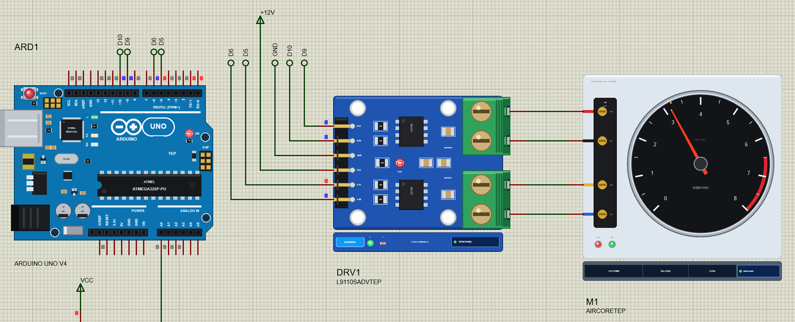
This library gives the air-core gauge a part of its own in Proteus, drawn as a 52 mm tachometer. Its two coils sit between four pins with their real resistance and inductance, and the needle follows the field they make - with the fluid damping, the pivot, the small return magnet and the stop pin of the real thing. A pop-up window draws the dial, the field vector and the coil currents, and tells you when the needle reads low, swings past or gets stuck. The demo drives it from an Arduino UNO V4.0 through our L9110S dual H-bridge on 12 V.
NOTICE: an air-core gauge looks like the simplest motor there is - two coils and a magnet - yet getting a smooth, accurate needle out of it takes some care: the right drive, a steady field, and never a jump of more than half a turn. Our team put a lot of effort into making this model behave like the real movement, including the ways it goes wrong. Your feedback is the fuel that keeps us going, so please tell us what you think in the comments below or in the Motor Driver board of our forum. And if our free libraries help you, you can buy us a coffee. So, let's get started with the Air-Core Gauge Library for Proteus V1.0:
What is an Air-Core Gauge?
An air-core gauge is a meter movement without an iron core - hence the name. Two coils are wound crossed at 90 degrees on a plastic bobbin, and a small disc magnet sits in the space inside them on the needle's shaft. The current in each coil makes a magnetic field along that coil's axis; the two fields add up to one field pointing somewhere in between, and the magnet simply turns to line up with it. Change the ratio of the two currents and the needle turns. Car makers used them for decades because they are cheap, robust, quick and need no calibration springs.
| Air-core gauge (the model) | |
|---|---|
| Coils | two, crossed at 90 deg: COS (COS+ / COS-) and SIN (SIN+ / SIN-) |
| Each coil | 230 ohm and 25 mH - a 12 V coil, 52 mA |
| The needle | points at atan2(SIN, COS): anywhere round the circle, -6 to 354 deg |
| Damping | a silicone fluid round the magnet: a move settles in about half a second |
| Return | a small return magnet: with the coils off the needle sinks back to 0 |
| The dial | a 52 mm tachometer, 0 - 8000 r/min over 270 deg, red from 6500 |
Two Coils and a Magnet
Call the coil along the needle's 0 mark the COS coil and the one at 90 degrees the SIN coil. Current only in the COS coil and the needle sits at 0. Current only in the SIN coil and it sits at 90 degrees. Reverse the current in the COS coil and it goes to 180. Any mix of the two points it in between: with the COS current at -0.71 and the SIN current at +0.71 of the full value, the field points at 135 degrees, which on our dial is 4000 r/min. Because the magnet follows the field rather than a spring, the reading does not depend on the supply voltage - only on the ratio of the two currents.
Cos and Sin: Pointing the Needle
So the recipe for any angle is simple: drive the COS coil with cos(angle) and the SIN coil with sin(angle). Each coil needs its current in both directions, so each one gets its own H-bridge. A microcontroller makes the size with a PWM on one input of the bridge and the direction by choosing which input gets it. When cos^2 + sin^2 = 1 the field keeps the same size all round the dial, and the needle is equally firm everywhere.
Why Not a Stepper?
Modern clusters often use small gauge steppers instead, like the one in our X27.168 Speedometer Gauge Library for Proteus. A stepper moves in fixed steps, needs a zeroing run at power-up and can lose steps; an air-core movement has no steps at all - it turns smoothly to wherever the field points and always knows where that is. In return it needs more current (12 V coils, about 52 mA each) and two H-bridges, and it has one famous trap: ask it to jump more than half a turn and the magnet takes the short way round.
What's New in Air-Core Gauge Library for Proteus V1.0
- A part of its own: a 52 mm car tachometer on an air-core movement, the coils between COS+ / COS- and SIN+ / SIN-.
- The real coils: 230 ohm and 25 mH each in the circuit, so any H-bridge drives them.
- The real movement: the needle follows the field, the fluid damps it, the pivot and the return magnet pull it a little off, the stop pin blocks it.
- The real traps: STUCK AT THE PIN after a jump of more than 180 degrees, WEAK FIELD when the current is too low, a coil without current.
- Properties: RANGE and REDLINE set the scale, RETURN switches the return magnet.
- A pop-up window with four pages - Gauge, Graphs, Event log and Check - with the field vector drawn the dial's way round.
- An A3 demo on our Arduino UNO V4.0 and our L9110S driver: a self-test sweep, a knob, a rev and every trap on command.
The Air-Core Gauge in Proteus
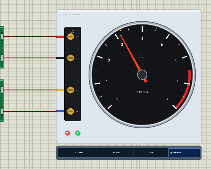
Search air-core in Pick Devices; the device AIRCORETEP is in TEPAIRCORE.LIB (category Electromechanical, Motors) and its model is TEPAIRCORE.DLL. It is drawn as a car tachometer from the front: the chrome bezel, the black face with its 0 - 8 x1000 r/min scale over 270 degrees and the red zone, the red needle and its hub, and on the left the movement's terminal block with four brass terminals and the coil wires to the pins.
At Run the needle turns to the simulated angle, and a small orange mark on the rim shows where the field points - when the two disagree, you see it at once. The coil LEDs COS and SIN light green while their current flows + to - and red the other way. Under the plate the strip shows the reading, the angle, the field current and the OPEN PANEL button. The plate, the LEDs, the rating line and the strip are TEP additions; the real gauge has none of them.
The Pins and the Properties
| Pin | What the model does with it |
|---|---|
| COS+ / COS- | the COS coil (along the needle's 0): the L9110S's motor B in the demo |
| SIN+ / SIN- | the SIN coil (along 90 deg): the L9110S's motor A in the demo |
| Property | Default | What it does |
|---|---|---|
| RANGE | 8000 | r/min at the end of the 270 deg scale (2000 - 20000; the numbers in thousands) |
| REDLINE | 6500 | where the red zone starts |
| RETURN | YES | the return magnet: YES, the needle sinks back to 0 with the coils off; NO, it stays put |
A click on the dial while the simulation runs puts a finger on the needle; the pop-up's Tap the gauge chip knocks it, and you can watch the fluid settle it back.
Download Air-Core Gauge Library for Proteus
Click the button below to download Air-Core-Gauge-Library-for-Proteus-v1.0.zip (about 1.2 MB, without the source code of the models):
Air-Core Gauge Library for Proteus V1.0- README.txt: installation, the demo, the wiring, the properties, real hardware, troubleshooting and the limits.
- Proteus Library Files:
TEPAIRCORE.LIBandArduinoV4TEP.LIBfrom our Arduino Library for Proteus V4.0. - Proteus Model Files:
TEPAIRCORE.DLLandTEPARDUINO.DLL. - Proteus Simulation:
Air-Core-Gauge-L9110S-ArduinoUnoV4.pdsprj,AirCore_Gauge_Demo.hexand copies of the two DLLs. - Arduino Code:
AirCore_Gauge_Demo.ino(no library needed).
Important: the L9110S driver of the demo is not in this package. It is our separate L9110S Motor Driver Library for Proteus: download it from its own article and install its TEPL9110S.LIB and TEPL9110S.DLL first, then this library.
No Proteus yet? Read How to Download and Install Proteus 7 and 8. New to libraries? Follow How to Install a New Library in Proteus.
How to Install Air-Core Gauge Library for Proteus
- Close Proteus and extract the whole zip file, for example to your Desktop.
- Copy
TEPAIRCORE.LIBandArduinoV4TEP.LIBfrom Proteus Library Files into the LIBRARY folder of Proteus (usuallyC:\Program Files (x86)\Labcenter Electronics\Proteus 8 Professional\LIBRARY). - Copy
TEPAIRCORE.DLLandTEPARDUINO.DLLfrom Proteus Model Files into the MODELS folder. The two Arduino files are the ones of our Arduino Library V4.0; if you have it, they are the same. - For the demo, install our L9110S library the same way:
TEPL9110S.LIBinto LIBRARY andTEPL9110S.DLLinto MODELS. - Delete
TEPAIRCORE.IDXfrom the LIBRARY folder if it is there. - Start Proteus, press P and search for air-core.
Tip: keep the Proteus Simulation folder together, because the project needs its .hex file and the DLLs beside it. The library is tested in Proteus 8.5; Proteus 7 is not supported.
The Demo Circuit
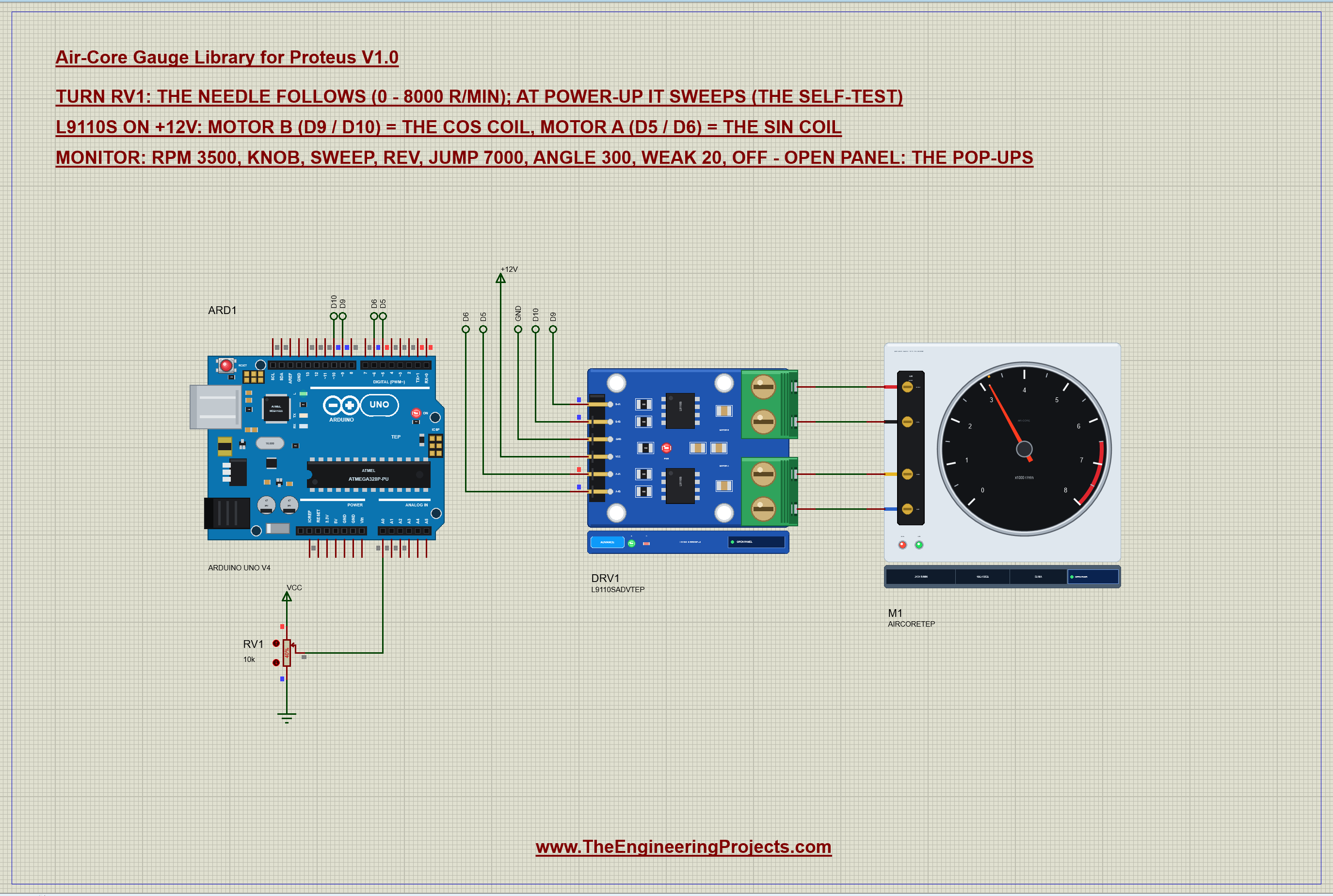
Open Air-Core-Gauge-L9110S-ArduinoUnoV4.pdsprj. ARD1 is an Arduino UNO V4.0 from our Arduino UNO Library for Proteus V4.0, running AirCore_Gauge_Demo.hex with its serial monitor built in. DRV1 is the L9110S dual H-bridge from our separate driver library, in its pop-up version, on +12V. M1 is the gauge and RV1 a 10k pot on A0 that sets the r/min in knob mode.
| Part | Pin | Goes to |
|---|---|---|
| L9110S | B-IA / B-IB | D9 / D10 (PWM): the COS coil |
| L9110S | A-IA / A-IB | D5 / D6 (PWM): the SIN coil |
| L9110S | VCC, GND | +12V, GND |
| Gauge | COS+ / COS- | the L9110S's B-OA / B-OB |
| Gauge | SIN+ / SIN- | the L9110S's A-OA / A-OB |
| RV1 | wiper | A0 |
Why an H-Bridge?
Two reasons. A car gauge's coils are 12 V parts taking about 52 mA each - more than twice what a microcontroller pin should give. And each coil needs its current in both directions, which a single pin cannot do. The L9110S has two H-bridges, one for each coil, takes 2.5 - 12 V and accepts 5 V logic on its inputs, so it fits the job exactly. The gauge's pins are placed so the wires from the driver's terminals run straight across.
The Arduino Code
The sketch needs no library. New to Arduino? Start with Arduino Tutorial for Beginners and Introduction to Arduino UNO. Four PWM pins drive the two H-bridges:
const byte SIN_A = 5, SIN_B = 6;              // L9110S A-IA / A-IB: the SIN coil (A-OA / A-OB to SIN+ / SIN-)
const byte COS_A = 9, COS_B = 10;             // L9110S B-IA / B-IB: the COS coil (B-OA / B-OB to COS+ / COS-)
One small function drives one coil with a value from -1 to 1: the size becomes a PWM duty on one input, the sign picks which input, and the other input stays LOW:
void coil(float x, byte pa, byte pb) {        // x in -1 .. 1: PWM on one input, the other LOW (the sign picks the input)
  int d = constrain(int(fabs(x) * 255 + 0.5), 0, 255);
  if (x >= 0) { analogWrite(pb, 0); analogWrite(pa, d); }
  else { analogWrite(pa, 0); analogWrite(pb, d); }
}
Pointing the needle is then just cos and sin:
void drive(float deg) {                       // the field at deg: COS = cos(deg), SIN = sin(deg)
  float r = deg * PI / 180;
  coil(coilsOn ? amp * cos(r) : 0, COS_A, COS_B);
  coil(coilsOn ? amp * sin(r) : 0, SIN_A, SIN_B);
}
A reading becomes an angle on the 270-degree scale:
float degFor(float rpm) { return constrain(rpm, 0, RANGE) / RANGE * SWEEP; }The most important line is the slew. The sketch never sets the field to a new angle at once; every 10 ms it turns it at most 4 degrees towards the target, so the field can never jump more than half a turn:
const float SLEW = 4; // deg the field may turn every 10 ms (400 deg/s) field += constrain(target - field, -SLEW, SLEW);
drive(field);At power-up it does what a car cluster does - a self-test sweep to the end of the scale and back - and then follows the knob:
if (mode == 1) target = degFor(analogRead(KNOB) / 1023.0 * RANGE);Only one command breaks the rule on purpose. jump 7000 sets the field at once, to show what happens:
mode = 0; target = field = degFor(atof(s + 4)); drive(field);The HEX file is in the package. To change the sketch, open it in the Arduino IDE and export the compiled binary, as in How to get the HEX file from Arduino. It needs 9,070 bytes of flash (28 % of the UNO) and 316 bytes of RAM.
Running the Demo
Press Run. The UNO's serial monitor and the two pop-ups - the gauge's and the driver's - open over the schematic; move them aside. The needle sweeps to 8000 r/min and back, and then RV1 takes over:
Air-Core Gauge demo - The Engineering Projects
L9110S on 12 V: COS coil on motor B (D9 / D10), SIN coil on motor A (D5 / D6).
Self-test sweep, then the knob (RV1).
Commands: rpm 3500 | knob | sweep | rev | jump 7000 | angle 300 | weak 20 | full | off | on | help
Sweep done - the knob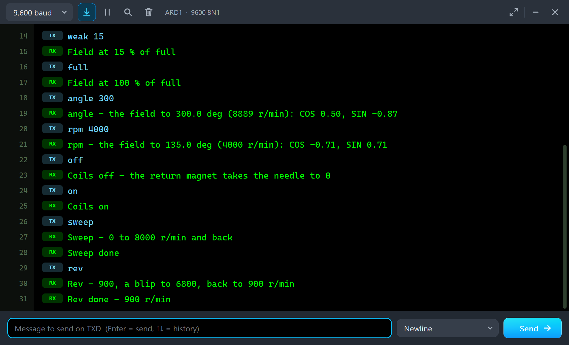
With RV1 at 40 %, the Event log reads "STEADY at 3162 r/min (106.7 deg) - from 23 r/min in 2.00 s, 0.3 deg off the field" - the two seconds include the self-test sweep. The COS coil takes -17 mA and the SIN coil 49 mA: at 106.7 degrees the cosine is small and negative and the sine nearly 1.
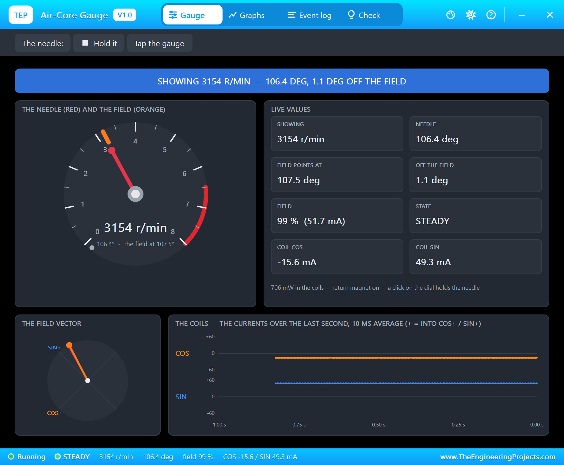
The pop-up has the look of our TEP Serial Monitor Advance for Proteus and four tabs: Gauge, Graphs, Event log and Check. The Gauge page is built around one idea - the needle follows the field. The dial draws the needle in red and the field as an orange mark; the field vector at the bottom left draws the two coil currents as one arrow, turned the same way as the dial, so the needle lies along the arrow when all is well. Next to it the two coil currents run over the last second.
Into the Red Zone
Type rpm 6800. The field slews up at 400 degrees a second and the needle follows into the red:
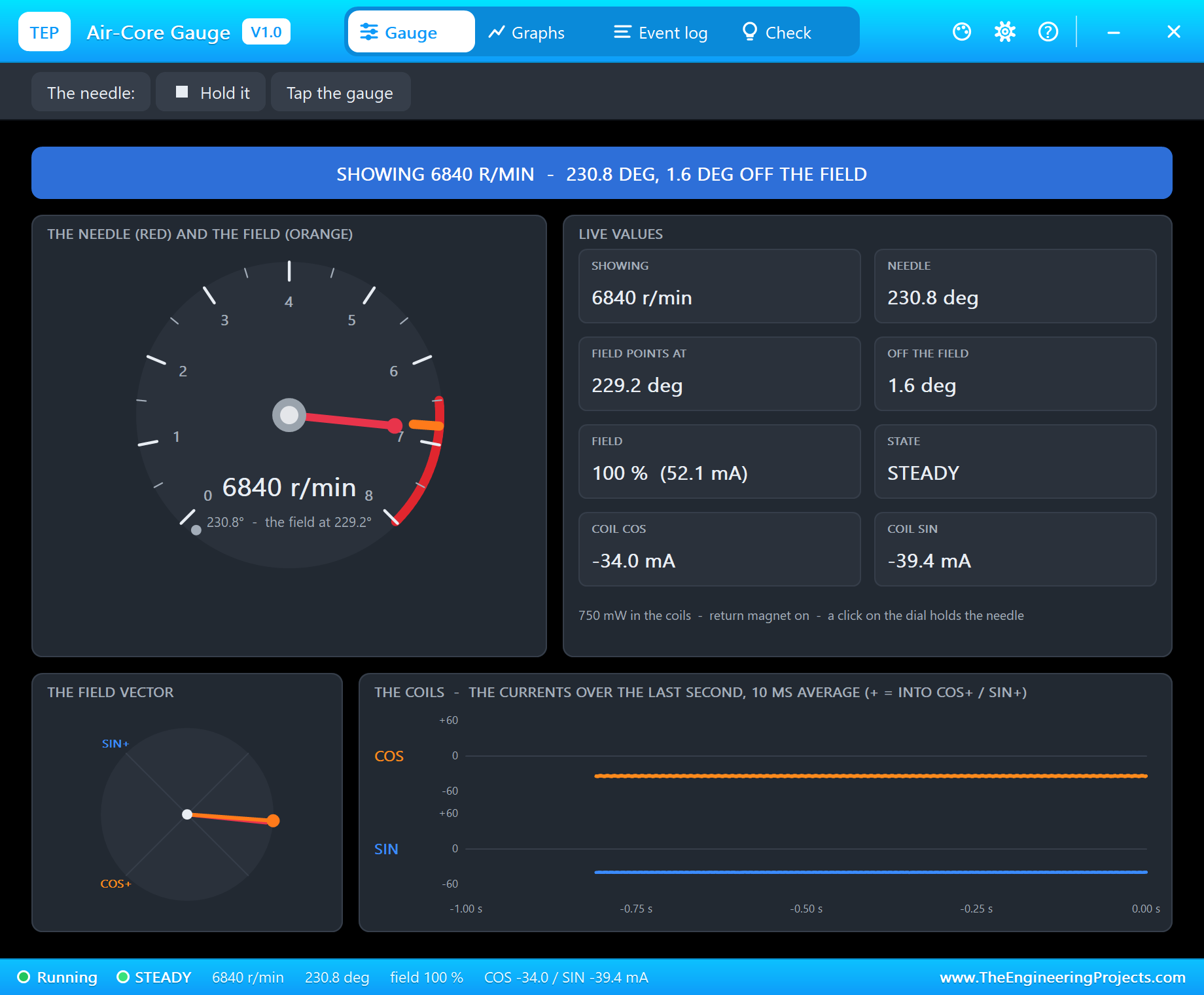
At 230.8 degrees both the cosine and the sine are negative, so both coils carry their current backwards and both coil LEDs turn red. The needle reads 6839 r/min instead of 6800 - the 1.5 degrees between the needle and the field are the pull of the return magnet and the pivot, and they are part of every real air-core gauge.
The Jump: Stuck at the Pin
Now the classic mistake. Type rpm 900, wait, then jump 7000. The field jumps from 30 to 236 degrees at once - 206 degrees, more than half a turn:
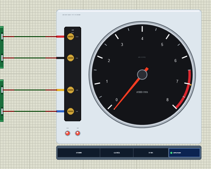
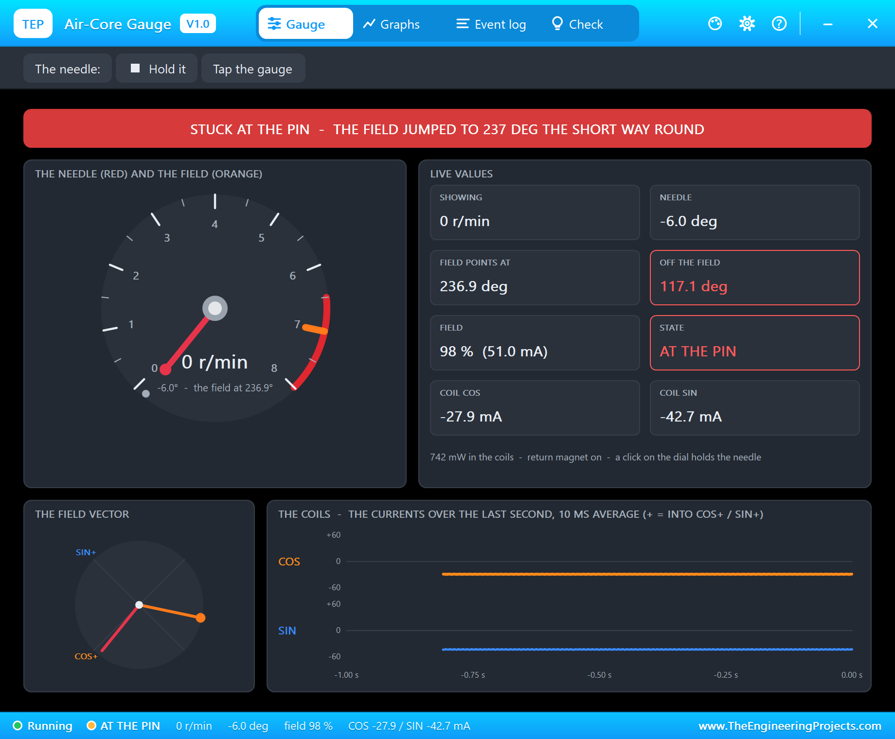
The magnet does not know which way the sketch meant. From 30 degrees, a field at 236 degrees is closer the other way round - counter-clockwise - so the needle swings down, hits the stop pin below 0 and stays there, pushed against it. The log says it plainly: "STUCK AT THE PIN - the field jumped to 236 deg the short way round: move it in steps under 180 deg". Type rpm 3000: the sketch slews the field back down, and once it passes the point opposite the pin, the pull reverses and the needle frees itself - "STEADY at 2948 r/min (99.5 deg)". This is exactly why the sketch slews.
A Weak Field
weak 15 scales both coils down to 15 %. The ratio, and so the direction, stays the same - but the field holds the needle only loosely:
weak 15
Field at 15 % of full
full
Field at 100 % of full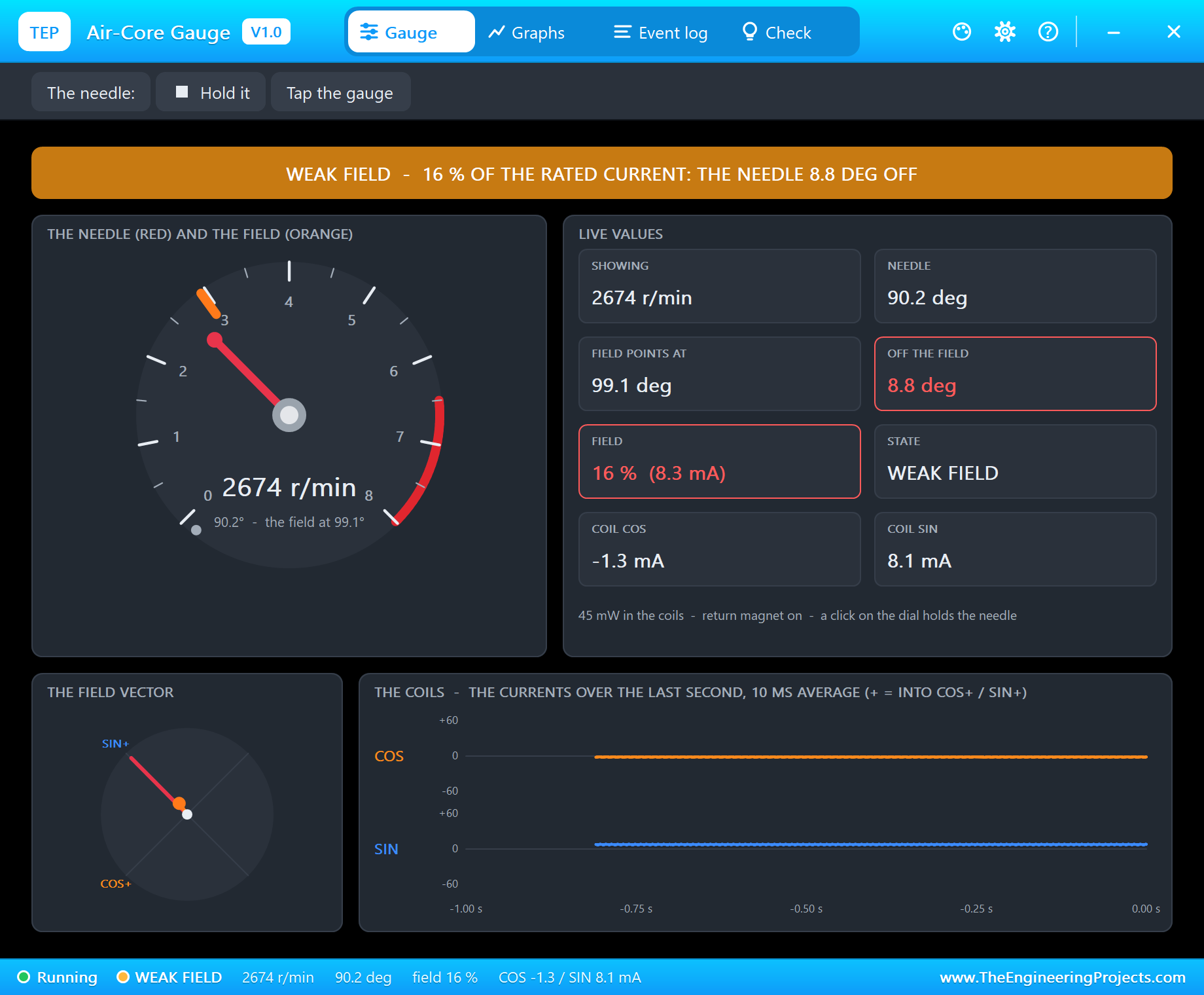
The log reads "WEAK FIELD - 15 % of the rated current: the needle sits 6.5 deg off the field", and the needle keeps sinking until it is about 12.5 degrees low - nearly 400 r/min. The pull of the return magnet and the pivot is always there; a full field makes it small, a weak one does not. On a real gauge this is what a low supply or a wrongly scaled drive looks like.
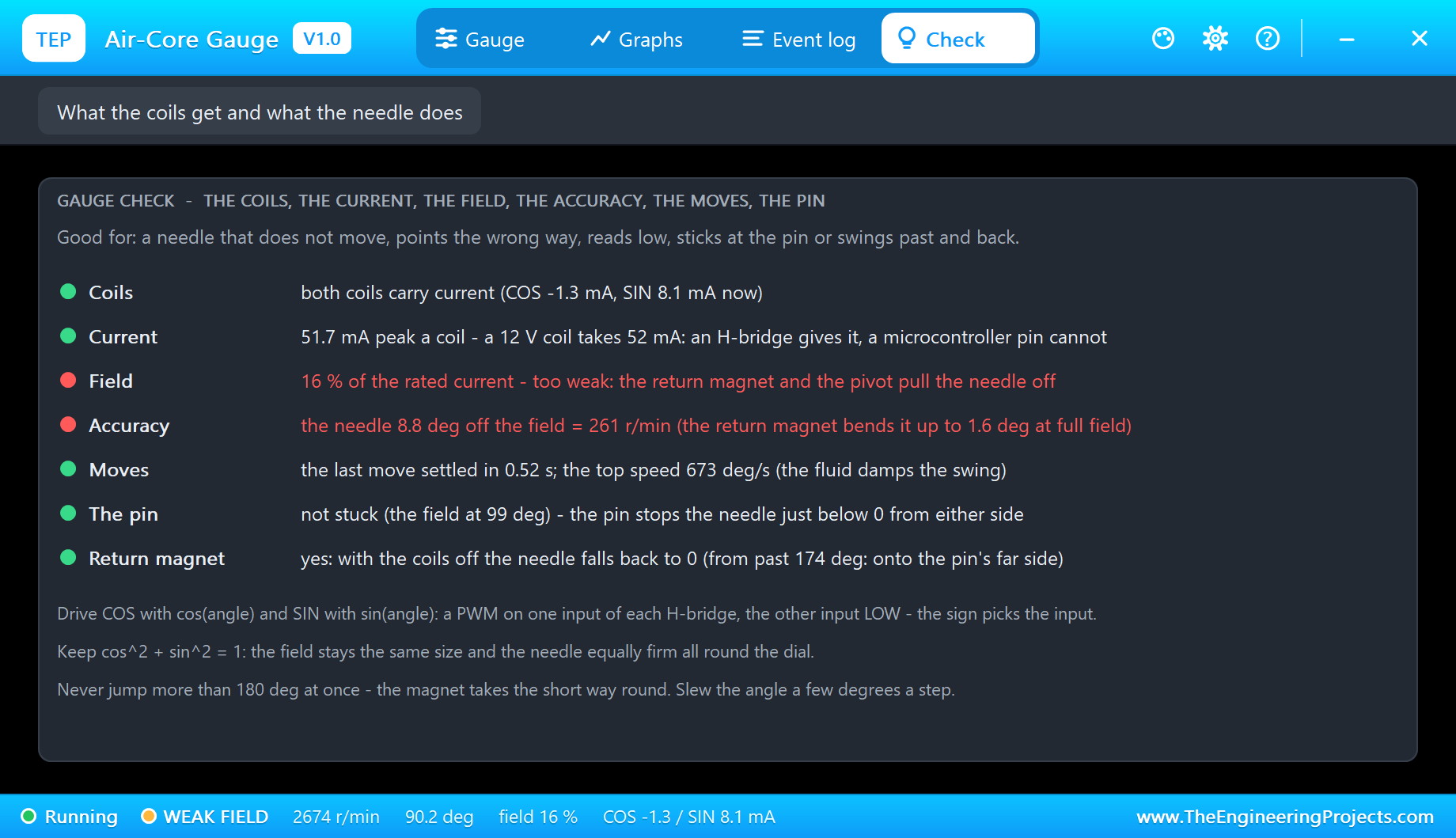
The Check page goes through the coils, the current, the field, the accuracy, the moves, the pin and the return magnet, and its tips sum up the drive: cos and sin, a constant field, and no jumps over 180 degrees. full brings the field back to 100 %.
Past the Scale
An air-core needle is not limited to the printed scale. angle 300 sets the field beyond the 8000 mark:
angle 300
angle - the field to 300.0 deg (8889 r/min): COS 0.50, SIN -0.87
rpm 4000
rpm - the field to 135.0 deg (4000 r/min): COS -0.71, SIN 0.71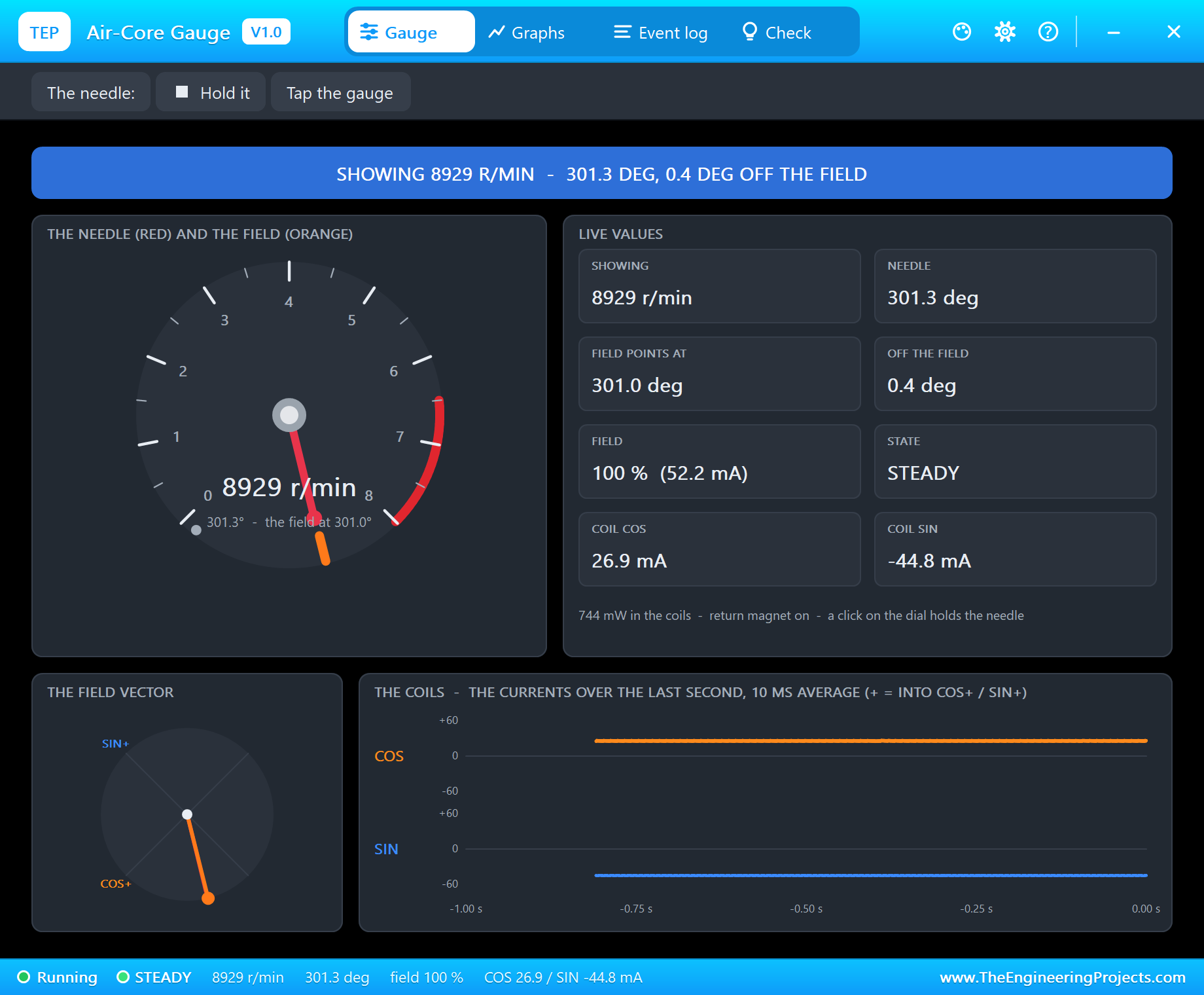
The needle turns past 8 to 301.3 degrees and the pop-up reads 8928 r/min. Only the stop pin limits it, from either side, between -6 and 354 degrees. A tachometer sketch should therefore clamp its reading; ours does in degFor().
Coils Off: the Return Magnet
With the needle at 4000 r/min, type off. The sketch drives both coils to zero:
off
Coils off - the return magnet takes the needle to 0
on
Coils on
sweep
Sweep - 0 to 8000 r/min and back
Sweep done
rev
Rev - 900, a blip to 6800, back to 900 r/min
Rev done - 900 r/min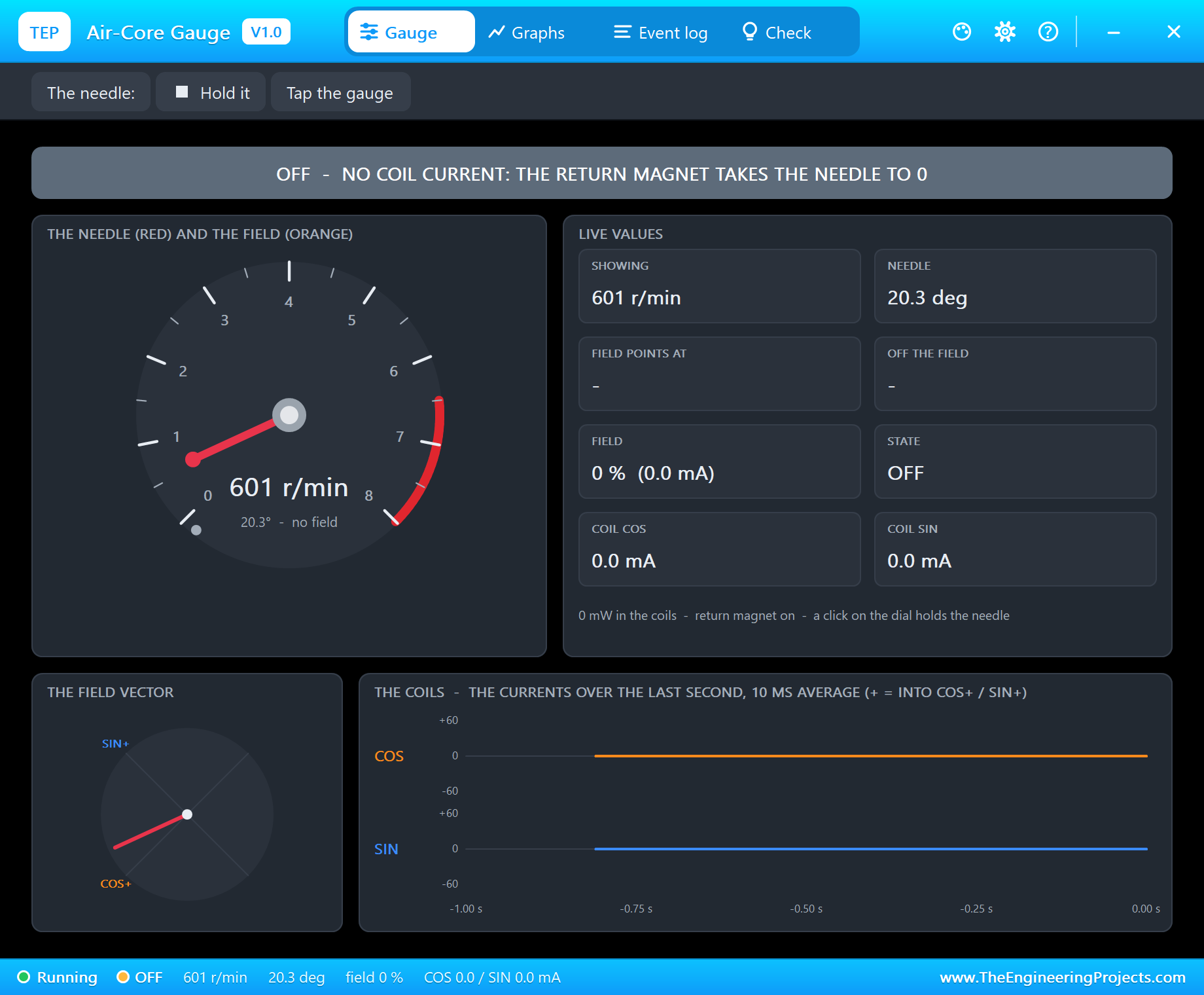
There is no field any more, so only the return magnet acts on the needle, and it is weak on purpose: the needle sinks slowly, from 133.9 to 20.4 degrees in 7 seconds, damped by the fluid. That is the slow fall you see on a real fuel or temperature gauge when the ignition goes off. Set the property RETURN to NO and the needle stays where it was instead. on brings the field back, sweep repeats the self-test and rev shows an engine blip from idle.
Graphs, Log and the Driver
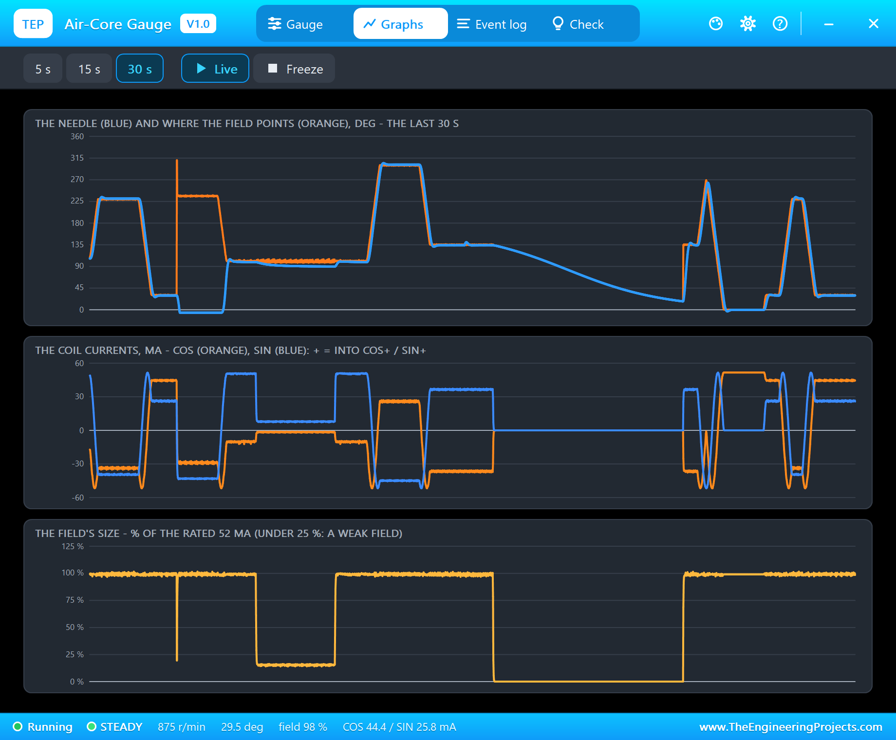
Graphs draws the needle and the field, the two coil currents and the field's size over the last 5, 15 or 30 seconds. In this run you can read the whole story: the needle following the field through the moves, the gap opening during the weak field and while the coils are off, and the currents tracing a cosine and a sine through the sweep and the rev.
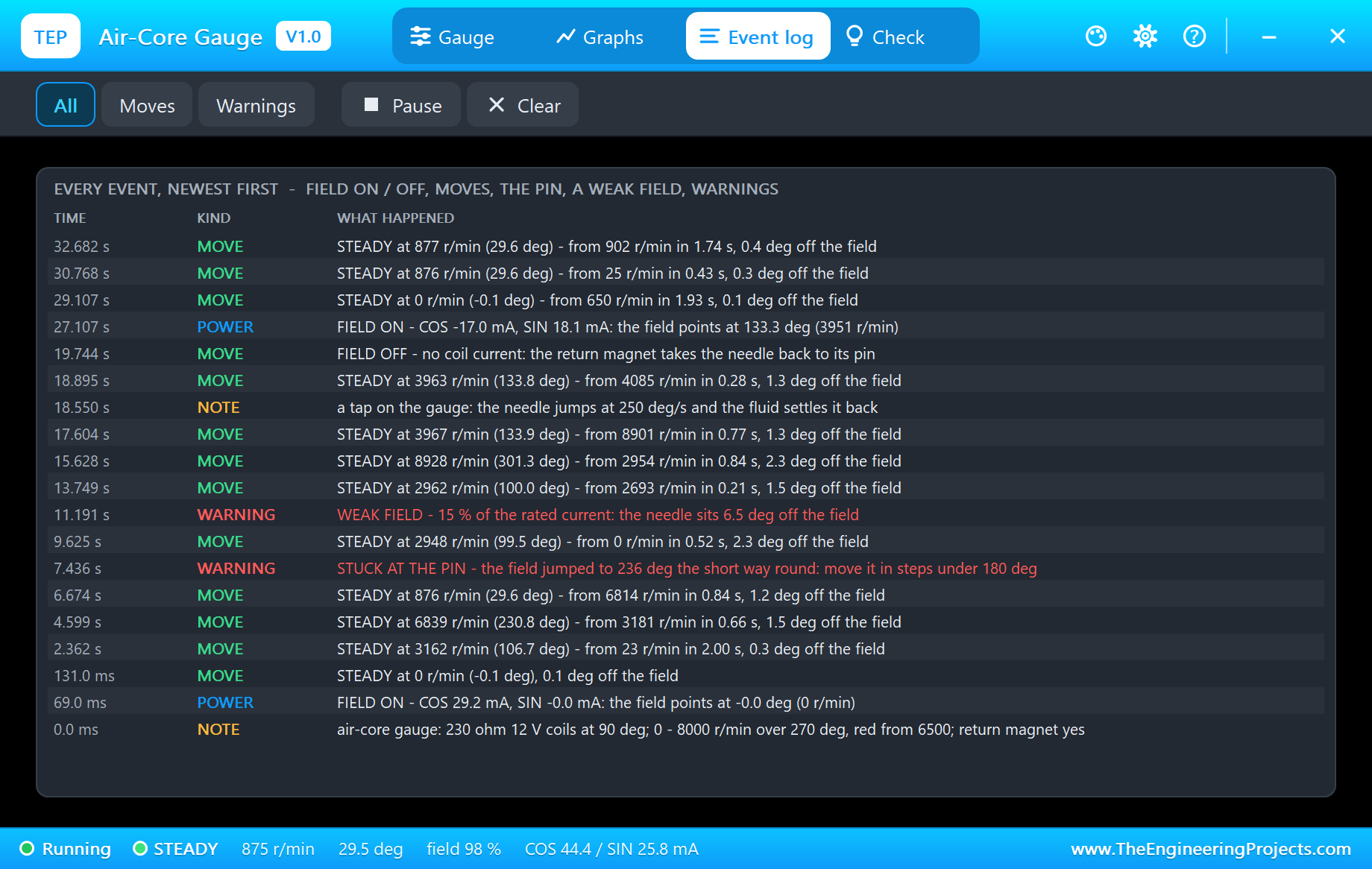
The Event log keeps every move with where it came from, how long it took to settle and how far the needle stayed off the field. The tap is there too: "a tap on the gauge: the needle jumps at 250 deg/s and the fluid settles it back", steady again in 0.28 s.
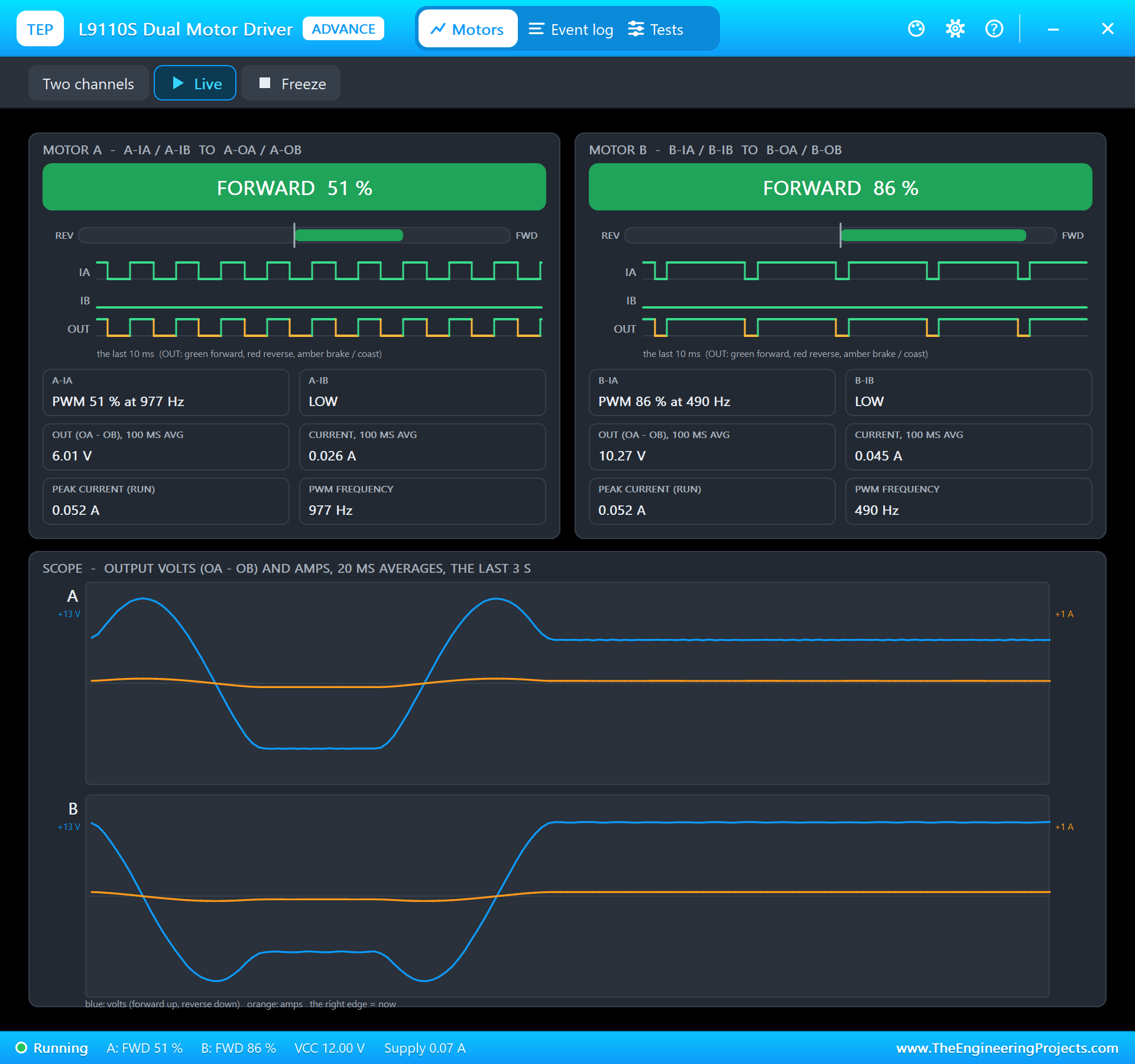
The driver's own pop-up shows the other side of the drive. At 900 r/min the field points at 30 degrees, so the COS coil gets 86 % (cos 30 = 0.87) on motor B and the SIN coil 51 % (sin 30 = 0.50) on motor A, with the PWM of D9 at 490 Hz and of D5 at 977 Hz. Its scope draws the two coil voltages as a cosine and a sine through the sweep and the blip.
How the Model Works
Each coil is in the circuit as its backward-Euler companion over the analog step - a conductance and a source - so the H-bridge sees a real inductive load with the magnet's back-EMF. Between two analog points the needle runs in 100 microsecond steps: the torque of the field on the magnet, the fluid's damping, the pivot friction, the return magnet at the stop pin and the pin itself. The analog step is held to 200 microseconds while the needle moves or a current changes, and to 2 ms at rest.
The watch judges the field from the currents averaged over 10 ms, and the needle's speed over 20 ms. That matters with PWM: the torque pulses at the PWM frequency shake the needle's speed, but not where it points - so the gauge reads the average, as the real one does. From the field and the needle come the states - OFF, MOVING, STEADY, WEAK FIELD, AT THE PIN - the settle time, the error, and the warnings for too much current or a coil without any.
We checked the model on a PC with 39 automatic tests: the COS coil alone gives 52.2 mA and the needle at 0; 3500 r/min settles within 2 degrees in half a second; a step to 170 degrees overshoots to 175 and settles; a jump from 0 to 270 sticks at the pin while the same move in steps arrives; the coils off bring the needle back to 0, or from 300 degrees onto the pin's far side; a 15 % field is weak; a PWM on the coils reads as its average; a dead coil, over-current, a finger and a tap are all caught. The demo project is read back from disk with 75 checks.
For a gauge without the 12 V and the H-bridges, see our X27.168 Speedometer Gauge Library for Proteus, a tiny stepper that four Arduino pins drive directly. And the driver of this demo has its own article: the L9110S Motor Driver Library for Proteus.
Troubleshooting
- The needle does not move (OFF): no coil current - the L9110S has no 12 V, or its inputs are not driven.
- It points the wrong way or turns backwards: one coil's wires are swapped, or COS and SIN are swapped - the field vector shows it.
- It sits on the pin and will not come up: the field jumped more than 180 degrees - slew it in steps.
- It reads low and sluggish: a weak field - too little current, or cos and sin scaled down.
- "only the COS coil carries current": the SIN coil or its H-bridge is not connected.
- No driver in Pick Devices: install our L9110S library (
TEPL9110S.LIB/TEPL9110S.DLL). - No gauge, no UNO or no monitor:
TEPAIRCORE.DLLorTEPARDUINO.DLLis missing from MODELS and the project folder; a closed monitor opens again with a click on the UNO's USB port.
Things to Know Before Using a Real Air-Core Gauge
- A 12 V part: car air-core coils are 200 - 250 ohm, 50 - 60 mA each - use an H-bridge (L9110S, L293D, L298N) or a gauge driver chip (CS4192, CS8190), never a microcontroller pin.
- Find the coils with a meter: two pairs of terminals, about 230 ohm each. If the needle turns the wrong way, swap the two wires of one coil.
- Slew the field: a few degrees every 10 ms; a jump of more than 180 degrees sends the magnet the short way round.
- Keep the field constant: cos^2 + sin^2 near 1, so the needle is equally firm all round the dial.
Limitations of the Simulation
- Not modelled: the temperature drift of the coils and of the fluid, the magnet's cogging and a pointer's mechanical imbalance.
- The plate, the coil LEDs, the rating line and the strip are TEP additions.
- The model is our own, written from the typical data of automotive air-core gauge movements; this library is not made or endorsed by any gauge maker, Arduino or Labcenter.
- Licences: the demo HEX contains the Arduino AVR core 1.8.6 (LGPL); the sketch is included and the README gives the source link. The L9110S driver is our separate library.
- Tested in Proteus 8.5 in October 2026 with the demo as shipped: the self-test, the knob, the red zone, the jump and its recovery, the weak field, past the scale, the tap, off and on, all four pages of the pop-up and the driver's pop-up. Proteus 7 is not supported.
So, that was all about the Air-Core Gauge Library for Proteus V1.0. I hope it helps you build the dashboard you have in mind - a tachometer for your engine project, a sim-racing cluster or a retro gauge on your desk - and saves you from the needle stuck on its pin. If you have any questions, ask in the comments and I will help you out. Till the next tutorial, take care and have fun!