Hello friends, I hope you all are doing great. Today, I am going to share the new Electromechanical Counter Library for Proteus V1.0. Before every counter became a few digits on an LCD, counting was done by a small box with number drums behind a window and a coil inside: the electromechanical impulse counter. You still find it everywhere a count must survive a power cut and be readable at a glance - on packing lines, punch presses, coin mechanisms and arcade machines, hour meters and test rigs - and it is a favourite of makers who want a real, clicking tally for their projects.
Electromechanical Counter Library for Proteus
Latest version: V1.0 (November 2026, this tutorial)
Other motors: SG90 Servo · TT Gear Motor · 28BYJ-48 Stepper · NEMA 17 Stepper · MG996R Servo · N20 Encoder Motor · JGA25-370 Encoder Motor · FS90R 360 Servo · 130 DC Motor · A2212 Brushless · X27.168 Gauge · Analog Panel Meter · DC Tachogenerator · LM393 Speed Sensor · MG90S Servo · DS3218 Servo · L12 Linear Servo · JGB37-520 Motor · RS-775 Motor · JGY-370 Worm Motor · 12V Linear Actuator · Coin Vibration Motor · Mini Submersible Water Pump · 12V Peristaltic Pump · 4-Pin PC Fan · 12V Push-Pull Solenoid · NEMA 23 Stepper Motor · Micro Linear Stepper · TYJ50 Synchronous Motor · Quartz Clock Movement · Air-Core Gauge · Split-Flap Display · Electric Bell · Wind Turbine · 8520 Coreless Motor · Car Wiper Motor · Car Door Lock Actuator · 12V Solenoid Water Valve · 12V Holding Electromagnet
Motor drivers: L298 · L9110S · TB6612FNG · BTS7960 · A4988 / DRV8825 · 28BYJ-48 + ULN2003 · PCA9685 Servo · Relay Module · 30A Brushless ESC · TB6600 Stepper Driver
Helping Tools
- Serial Monitor Advance: a serial terminal window for the UART of your board
- Serial Monitor Expert: the serial monitor with extra debugging tools
- LCD Library for Proteus V3.0: 16x2, 20x4 and I2C LCDs to show your readings
This library gives the impulse counter a part of its own in Proteus, drawn as a 6-digit 12 V DC panel counter. Its coil sits between two pins with its real resistance and an inductance that changes as the armature moves, and the drums count only when a pulse really pulls the armature in and the spring really throws it back out - just like the real one. A pop-up window draws the drums, the coil current and the armature, and tells you exactly why a count was missed. The demo drives it from an Arduino UNO V4.0 through our L9110S driver on 12 V.
NOTICE: an impulse counter looks like the easiest output there is - a coil and some drums - yet a counter that misses one pulse in a hundred is worse than none. Our team put a lot of effort into making this model count the way the real one does, and miss the way the real one does, with the reason for every lost count. Your feedback is the fuel that keeps us going, so please tell us what you think in the comments below or in the Motor Driver board of our forum. And if our free libraries help you, you can buy us a coffee. So, let's get started with the Electromechanical Counter Library for Proteus V1.0:
What is an Electromechanical Counter?
An electromechanical counter (also called an impulse counter, a pulse counter or an electromagnetic counter) turns electrical pulses into a number you can read on rotating drums. Inside there is a small electromagnet: a coil on an iron core, and a hinged iron armature held away from it by a spring. Each pulse on the coil pulls the armature in; when the pulse ends, the spring throws it back, and a ratchet on the armature turns the units drum one digit on. Every drum carries the next one as it goes from 9 to 0, exactly like the odometer of an old car. Nothing is stored in electronics, so the count stays when the power goes off.
| Electromechanical counter (the model) | |
|---|---|
| Display | six number drums, 000000 - 999999, rolling over to 000000 |
| The coil | 144 ohm (at 25 C), 220 mH open / 400 mH closed - a 12 V, 83 mA, 1 W coil |
| A count | a full pull-in AND a full release: the drums move on the way out |
| Pull-in | from 55 mA (7.9 V on a 12 V coil); in after about 16 ms at 12 V |
| Release | about 22 ms after the coil switches off - then the count |
| Speed | up to about 18 counts a second (30 ms on, 25 ms off) |
| Reset | the red RESET button on the front; property START sets the drums at power-up |
How a Count Happens
Follow one pulse. The coil switches on and its current starts to rise - slowly, because the coil is an inductor. When it passes about 55 mA, the pull beats the spring and the armature starts to move. As it moves, the air gap closes and the inductance grows, and this makes something you can see on any electromagnet that moves: the current dips while the armature travels, from 82 to 65 mA, and then climbs back to 83 mA once it is in. The armature is fully in about 16 ms after the pulse started. When the pulse ends, the current dies away, the spring wins, and about 22 ms later the armature is back out - and that return stroke turns the drums. That is one count.
Why the Count Comes on the Release
This surprises many people the first time: the drums do not move when the pulse starts, they move when it ends. The ratchet pawl drops into the next tooth on the way in and pushes the wheel on the way out, driven by the spring rather than by the coil. That is a clever design - the spring gives the same push every time, whatever the supply voltage - but it means a count needs two things: a pulse long enough for the armature to close, and a pause long enough for it to get back out. Too little of either and the count is lost, without a sound.
Where You Find Them
Production counters on conveyors and presses, total counters on coin and ticket machines, the famous coin meters of arcade cabinets, hour meters on engines and pumps, test counters on endurance rigs, and plain tally counters on a desk. In an Arduino project, an impulse counter is a lovely way to show a total that never resets by accident: visitors through a door, laps of a model railway, shots of a nerf turret, or days without an accident in the workshop.
What's New in Electromechanical Counter Library for Proteus V1.0
- A part of its own: a 6-digit 12 V DC impulse counter with number drums, the coil between + and -.
- The real coil: 144 ohm with an inductance that grows as the armature closes, so any driver switches it and the pull-in dip shows in the current.
- The real counting: a count needs a full pull-in and a full release; the drums move on the release and carry from drum to drum, up to the rollover.
- Missed counts with their reason: too short, too weak, back too soon - plus HELD IN, the kick without a diode, the coil heating and too much current.
- Properties: VOLTAGE picks a 12 V or a 24 V coil, START sets the drums at power-up; RESET works on the sheet.
- A pop-up window with four pages - Counter, Graphs, Event log and Check - and Reset and Preset chips.
- An A3 demo on our Arduino UNO V4.0 and our L9110S driver: a knob for the rate, bursts, and every way to lose a count on command.
The Electromechanical Counter in Proteus
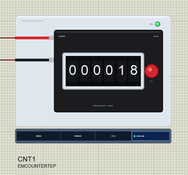
Search counter in Pick Devices; the device EMCOUNTERTEP is in TEPEMCOUNT.LIB (category Electromechanical, Motors) and its model is TEPEMCOUNT.DLL. It is drawn from the front: a black panel housing marked COUNTER and 12 V DC, the chrome-framed window with six white-on-black drums, the red RESET button on the right, and the two coil leads on the left, red for + and black for -.
At Run the drums show the simulated count, and the units drum rolls up as the armature comes back out, so you can catch a count half-way. The COIL LED lights green while the coil carries current. Under the plate the strip shows the count, the missed counts, the rate and the OPEN PANEL button. The plate, the LED, the rating line and the strip are TEP additions; the real counter has none of them.
The Pins and the Properties
| Pin | What the model does with it |
|---|---|
| + / - | the coil: the L9110S's A-OA / A-OB (motor A) in the demo; the model has no diode inside, so it counts either way round |
| Property | Default | What it does |
|---|---|---|
| VOLTAGE | 12 | the coil's rating: 12 (144 ohm, 83 mA) or 24 (576 ohm, 42 mA) |
| START | 0 | the drums at power-up, 0 - 999999 |
While the simulation runs, a click on the red RESET button turns the drums back to 000000, like the real button. The pop-up has two chips for the same job: Reset to 0 and Preset 999990, ten counts before the rollover.
Download Electromechanical Counter Library for Proteus
Click the button below to download Electromechanical-Counter-Library-for-Proteus-v1.0.zip (about 1.2 MB, without the source code of the models):
Electromechanical Counter Library for Proteus V1.0- README.txt: installation, the demo, the wiring, the properties, real hardware, troubleshooting and the limits.
- Proteus Library Files:
TEPEMCOUNT.LIBandArduinoV4TEP.LIBfrom our Arduino Library for Proteus V4.0. - Proteus Model Files:
TEPEMCOUNT.DLLandTEPARDUINO.DLL. - Proteus Simulation:
Electromechanical-Counter-L9110S-ArduinoUnoV4.pdsprj,Counter_Demo.hexand copies of the two DLLs. - Arduino Code:
Counter_Demo.ino(no library needed).
Important: the L9110S driver of the demo is not in this package. It is our separate L9110S Motor Driver Library for Proteus: download it from its own article and install its TEPL9110S.LIB and TEPL9110S.DLL first, then this library.
No Proteus yet? Read How to Download and Install Proteus 7 and 8. New to libraries? Follow How to Install a New Library in Proteus.
How to Install Electromechanical Counter Library for Proteus
- Close Proteus and extract the whole zip file, for example to your Desktop.
- Copy
TEPEMCOUNT.LIBandArduinoV4TEP.LIBfrom Proteus Library Files into the LIBRARY folder of Proteus (usuallyC:\Program Files (x86)\Labcenter Electronics\Proteus 8 Professional\LIBRARY). - Copy
TEPEMCOUNT.DLLandTEPARDUINO.DLLfrom Proteus Model Files into the MODELS folder. The two Arduino files are the ones of our Arduino Library V4.0; if you have it, they are the same. - For the demo, install our L9110S library the same way:
TEPL9110S.LIBinto LIBRARY andTEPL9110S.DLLinto MODELS. - Delete
TEPEMCOUNT.IDXfrom the LIBRARY folder if it is there. - Start Proteus, press P and search for counter.
Tip: keep the Proteus Simulation folder together, because the project needs its .hex file and the DLLs beside it. The library is tested in Proteus 8.5; Proteus 7 is not supported.
The Demo Circuit
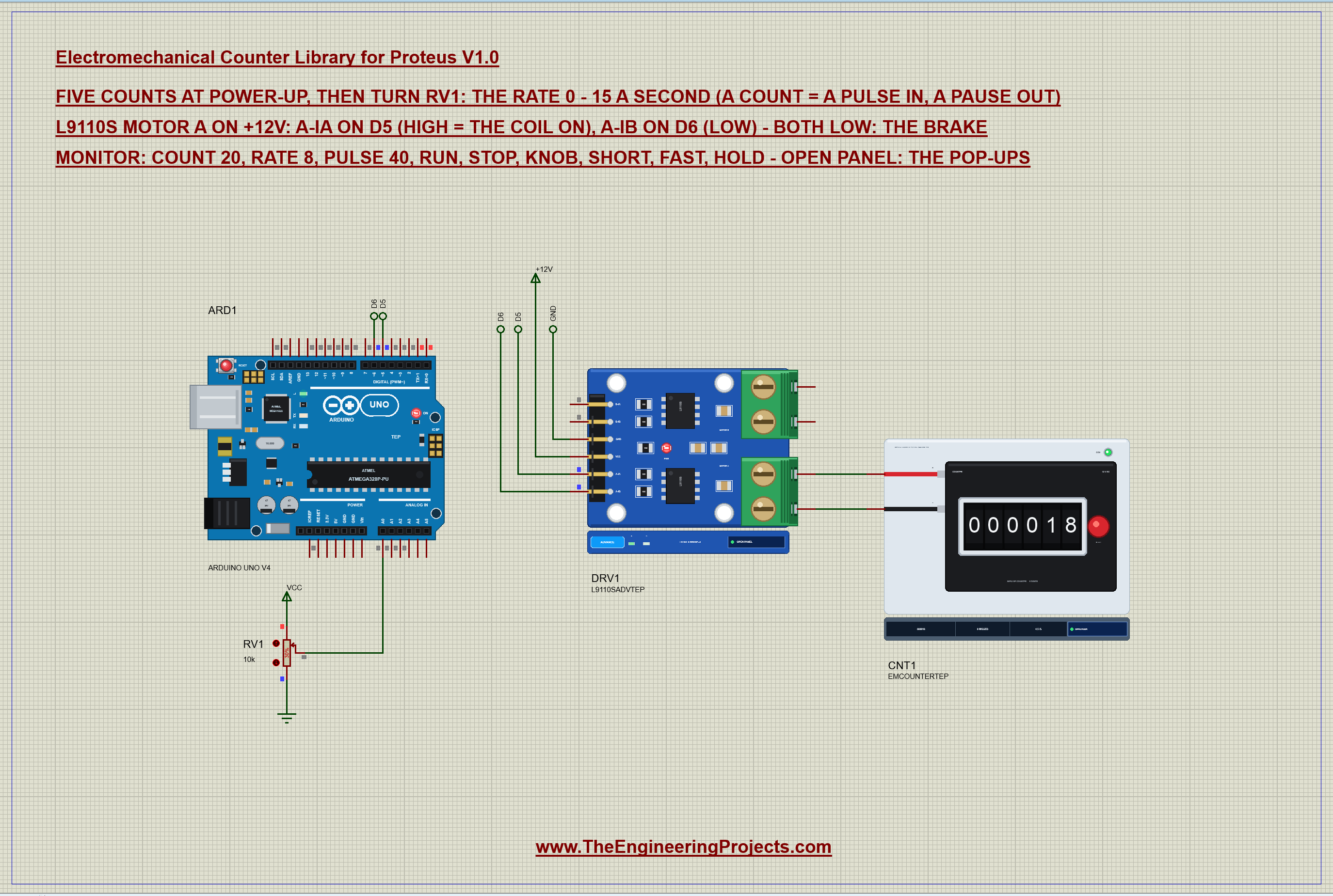
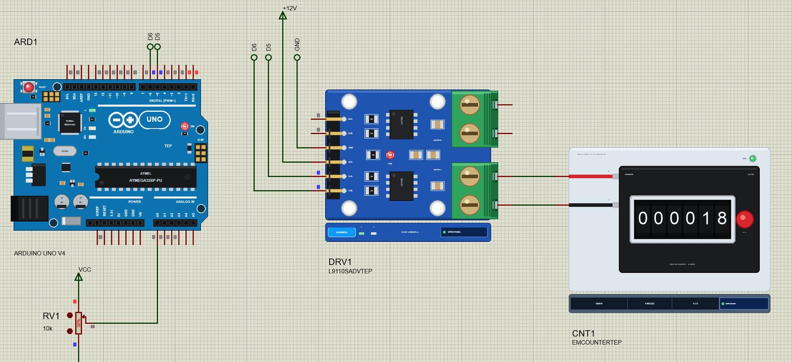
Open Electromechanical-Counter-L9110S-ArduinoUnoV4.pdsprj. ARD1 is an Arduino UNO V4.0 from our Arduino UNO Library for Proteus V4.0, running Counter_Demo.hex with its serial monitor built in. DRV1 is the L9110S from our separate driver library, in its pop-up version, on +12V. CNT1 is the counter and RV1 a 10k pot on A0 that sets the rate in knob mode, from 0 to 15 counts a second.
| Part | Pin | Goes to |
|---|---|---|
| L9110S | A-IA / A-IB | D5 / D6 |
| L9110S | VCC, GND | +12V, GND |
| Counter | + / - | the L9110S's A-OA / A-OB |
| RV1 | wiper | A0 |
Why a Driver for a Coil?
A 12 V counter coil takes about 83 mA at 12 V - far more voltage and current than an Arduino pin can give. It also needs somewhere for its current to go when it switches off, because a coil fights any sudden change of its current. With a plain transistor that is the job of a free-wheel diode across the coil. Our demo uses one channel of the L9110S instead: D5 HIGH and D6 LOW switch the coil on, and both LOW is the bridge's brake, which shorts the coil through its low side so the current dies away quietly - the diode's job, done by the bridge. The counter's pins are placed so the wires from the driver's terminals run straight across.
The Arduino Code
The sketch needs no library. New to Arduino? Start with Arduino Tutorial for Beginners and Introduction to Arduino UNO. Two pins drive motor A of the L9110S:
const byte COIL_A = 5, COIL_B = 6; // L9110S A-IA / A-IB (A-OA to +, A-OB to -)One small function switches the coil. The second input always stays LOW, so "off" is the brake:
void coil(bool c) { digitalWrite(COIL_A, c ? HIGH : LOW); digitalWrite(COIL_B, LOW); on = c; }A pulse starts the coil, notes the time and adds one to the sketch's own total:
void startPulse(unsigned long now) { coil(true); onAt = now; ++total; }The main loop ends each pulse after pulseMs - 40 ms by default - using millis() rather than delay(), so the serial monitor and the knob keep working while the counter counts:
  if (on && mode != 4 && now - onAt >= pulseMs) {
    coil(false);
The time from one pulse to the next comes from the rate, or from a fixed pause for the tests:
unsigned long period() { return gapMs ? pulseMs + gapMs : (unsigned long)(1000.0 / max(rate, 0.1f)); } startPulse(now);
nextAt = now + period();In knob mode RV1 sets the rate, from 0 to 15 counts a second:
if (mode == 1) rate = analogRead(KNOB) / 1023.0 * 15.0;One small detail matters a lot. When a new command starts a burst, the sketch never fires a pulse before the pause of the last one is over, because a cut pause is exactly how counts get lost:
void schedule() { if ((long)(nextAt - millis()) < 0) nextAt = millis(); } // keep a pulse already due later: never cut a pause shortThree commands break the rules on purpose, to show what goes wrong: short sends pulses far too short, fast gives the armature no time to get out, and hold leaves the coil on:
if (!strcmp(s, "short")) { pulseMs = 5; gapMs = 195; burst(3, F("Short")); return; } if (!strcmp(s, "fast")) { pulseMs = 40; gapMs = 4; burst(10, F("Fast")); return; } if (!strcmp(s, "hold")) { mode = 4; left = 0; startPulse(millis()); Serial.println(F("Hold - the coil stays on")); return; }The HEX file is in the package. To change the sketch, open it in the Arduino IDE and export the compiled binary, as in How to get the HEX file from Arduino. It needs 8,550 bytes of flash (26 % of the UNO) and 333 bytes of RAM.
Running the Demo
Press Run. The UNO's serial monitor and the two pop-ups - the counter's and the driver's - open over the schematic; move them aside. The sketch sends five counts at power-up, and then RV1 takes over:
Electromechanical Counter demo - The Engineering Projects
L9110S on 12 V: the counter on motor A (D5 / D6). A count = a pulse in and a pause out.
Commands: count 20 | rate 8 | pulse 40 | run | stop | knob | short | fast | hold | release | total | help
Count - 5 pulses, 40 ms each, 5.0 a second
Done - 5 pulses sent in all
Knob - RV1 sets the rate (0 - 15 a second)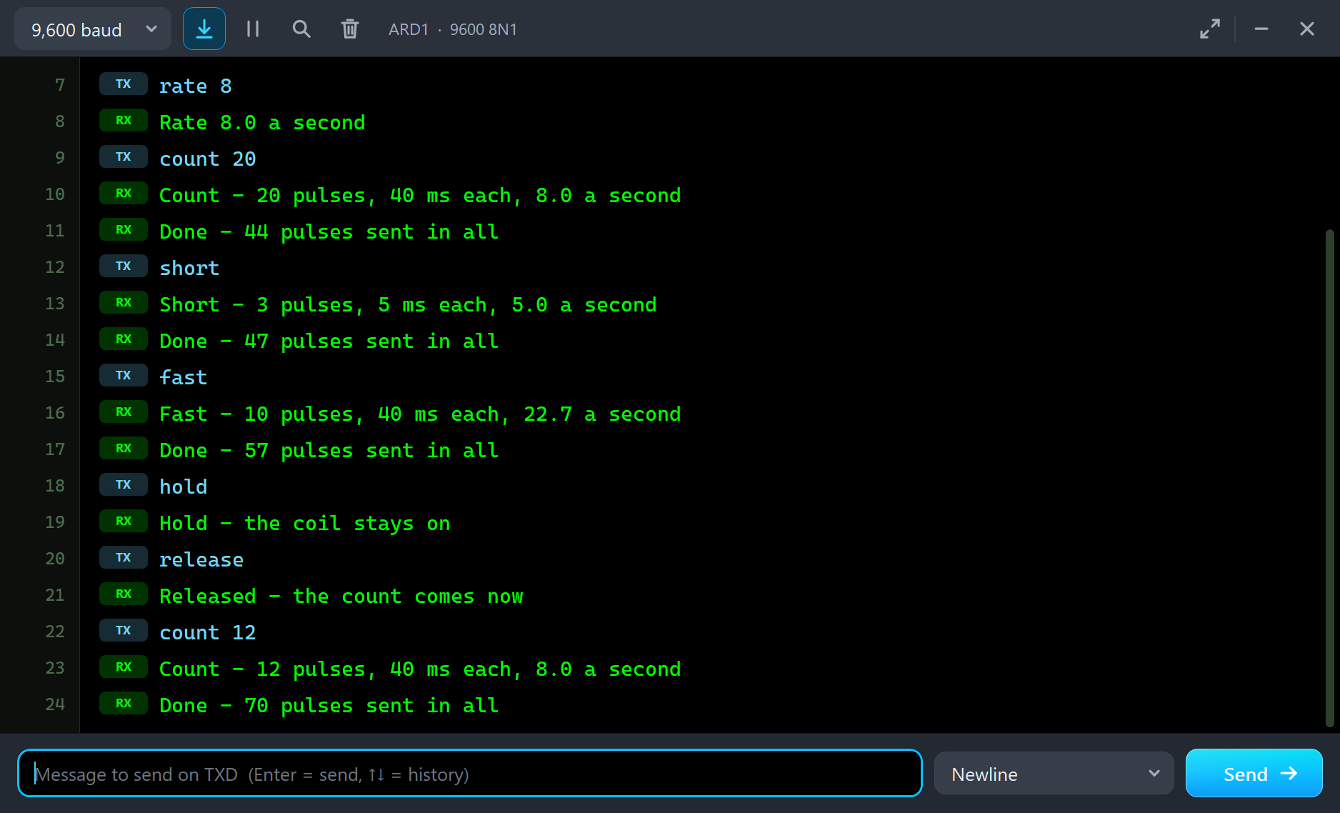
With RV1 at 30 % the rate is 4.5 counts a second, and the Event log opens with "COUNTING - from 000000 (the pulses 37 ms on)". Four seconds in, the drums show 000018:
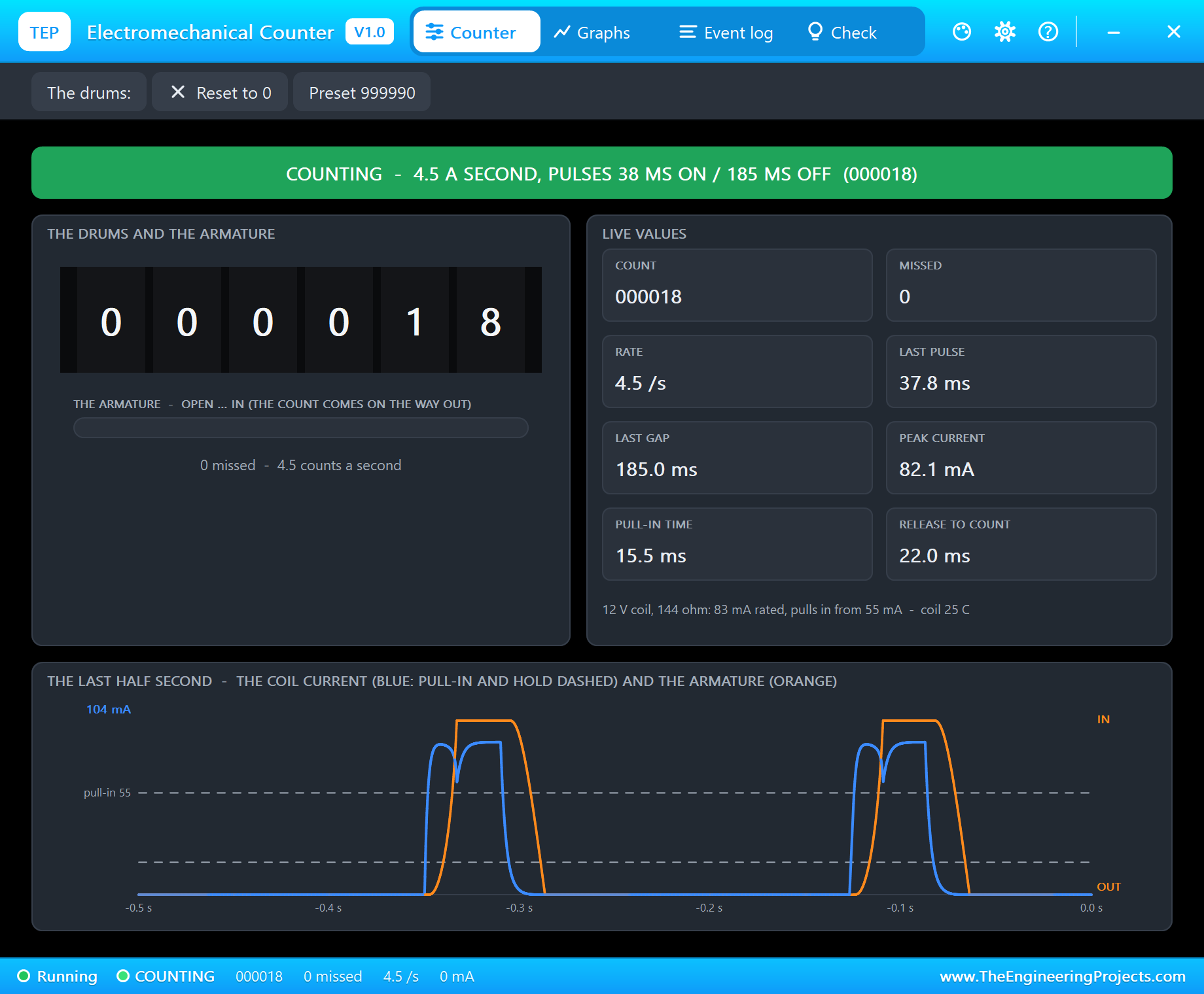
The pop-up has the look of our TEP Serial Monitor Advance for Proteus and four tabs: Counter, Graphs, Event log and Check. The Counter page shows the state in big letters - here "COUNTING - 4.5 A SECOND, PULSES 38 MS ON / 185 MS OFF" - then the drums with the armature's travel under them, and eight live values: the count, the missed counts, the rate, the last pulse, the last gap, the peak current, the pull-in time (15.5 ms) and the release to count (22.0 ms). The chart at the bottom is the heart of the page: the coil current in blue and the armature in orange over the last half second, with the pull-in and hold currents dashed.
Counting at Eight a Second
Type rate 8 and count 20. The sketch sends twenty pulses of 40 ms, eight a second:
rate 8
Rate 8.0 a second
count 20
Count - 20 pulses, 40 ms each, 8.0 a second
Done - 44 pulses sent in all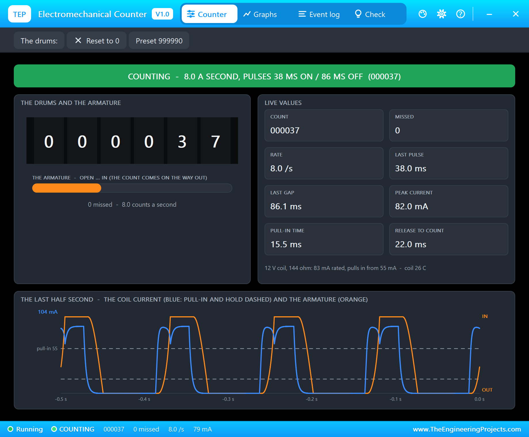
Look at one pulse in the chart. The blue current rises, then dips just as the orange armature starts to move, and rises again once the armature is in. That dip is the pull-in signature: the closing gap raises the coil's inductance, and the current has to catch up. After the pulse the current dies away in a few milliseconds through the brake, while the armature needs a little longer to travel back out - and the count comes at the end of that fall, not at the start of the pulse. At 38 ms on and 86 ms off there is time to spare on both sides, so nothing is missed. The burst ends with "Done - 44 pulses sent in all", and the drums agree: 000044.
Too Short: a Lost Count
Now the first way to lose counts. short sends three pulses of 5 ms with long pauses in between:
short
Short - 3 pulses, 5 ms each, 5.0 a second
Done - 47 pulses sent in all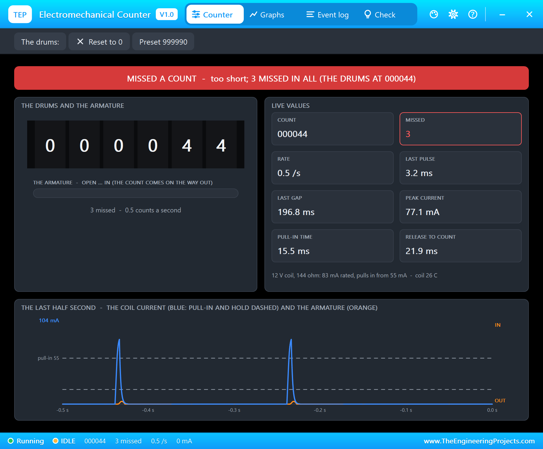
The L9110S passes them to the coil as pulses of about 3 ms, and the log reads "MISSED - a 3.2 ms pulse: the armature got 1 % in (it must close)" three times. Look at the chart: the current does climb past the 55 mA pull-in line - the coil is strong enough - but the armature has mass, and in 3 ms it hardly moves. No pull-in, no release, no count. The drums stay at 000044, while the sketch's own total says 47.
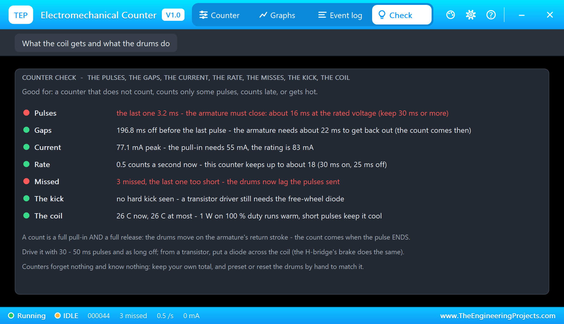
The Check page goes through the pulses, the gaps, the current, the rate, the misses, the kick and the coil. Here it says it straight: "the last one 3.2 ms - the armature must close: about 16 ms at the rated voltage (keep 30 ms or more)". Its tips sum up how to drive any impulse counter: 30 - 50 ms pulses and as long off, and a diode across the coil when a transistor drives it.
Back Too Soon: the Ratchet Never Resets
The second way is the opposite. fast sends ten good 40 ms pulses, but only 4 ms apart:
fast
Fast - 10 pulses, 40 ms each, 22.7 a second
Done - 57 pulses sent in all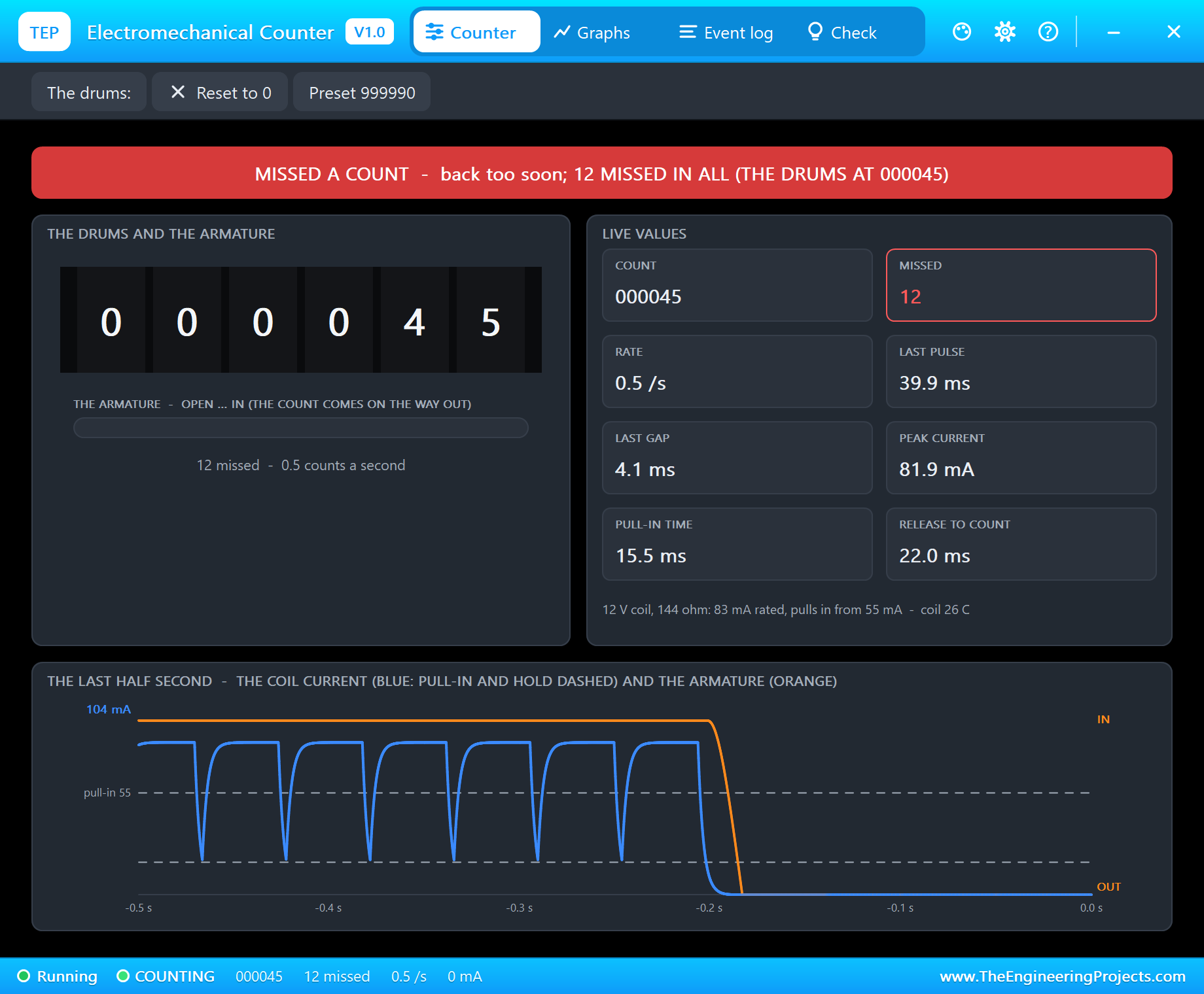
Each pulse is long enough, but every pause is too short. The current drops for 4 ms and comes back before the armature has even started to leave the pole, so the orange line stays at the top. The log fills with "MISSED - the coil came back 4 ms after the release: the armature had not left the pole" - nine times. Only the tenth pulse, with a long pause after it, ends in a count: 000045. A counter on a fast machine fails exactly like this, and on a real one nothing tells you; here the pop-up shows 12 missed in all.
Held In
hold switches the coil on and leaves it there. The armature pulls in and stays in, and nothing is counted:
hold
Hold - the coil stays on
release
Released - the count comes now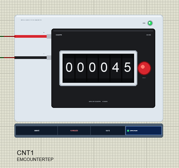
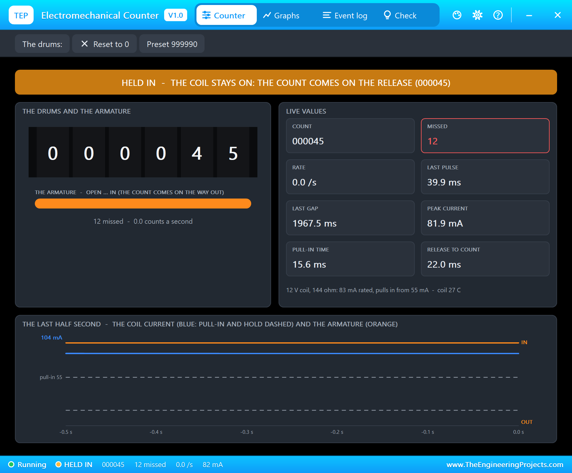
After a second the pop-up says "HELD IN - the coil stays on: the count comes when it is released", the armature bar is full and the coil takes a steady 82 mA. Nothing is wrong here, but the coil now turns a full watt into heat, and the Graphs page shows its temperature creeping up. release switches it off, the spring throws the armature out and the drums move on: 000046. Many machines use exactly this to count the end of a long event, such as a door that was opened and closed again.
The Rollover
Click the pop-up's Preset 999990 chip. The log notes "the drums preset to 999990 - ten counts to the rollover". Then type count 12:
count 12
Count - 12 pulses, 40 ms each, 8.0 a second
Done - 70 pulses sent in all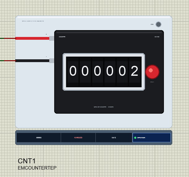
The log starts a new run with "COUNTING - from 999990", and twelve counts later the drums have gone through 999999, carried all six drums at once and come round to 000002 - the one count where the armature's return stroke turns every drum together. The monitor ends with "Done - 70 pulses sent in all": 58 before the preset, of which 46 were counted and 12 missed, and 12 after it.
Graphs, Log and the Driver
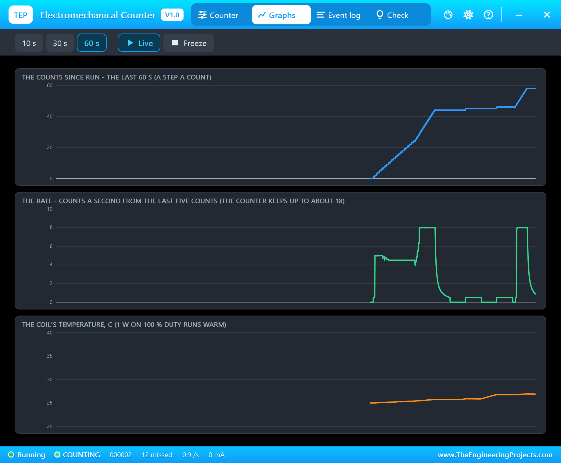
Graphs draws the counts since Run, the rate and the coil's temperature over the last 10, 30 or 60 seconds. The whole demo is in it: the knob's steady 4.5 a second, the burst at 8, the flat steps where the short and fast pulses were lost, the hold, and the final burst through the rollover. The rate is taken from the spacing of the last five counts, so it jumps straight to the new value when the rate changes. The coil stays cool at these duties - a few degrees above the room.
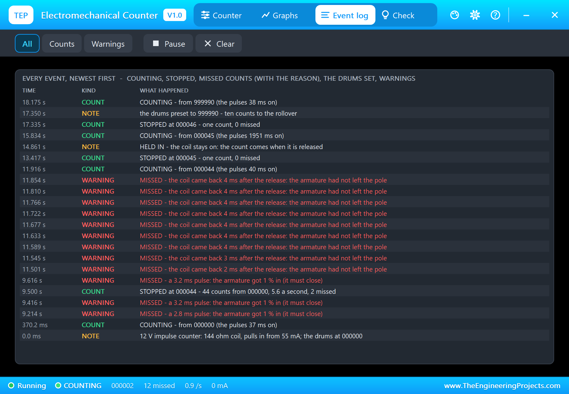
The Event log keeps every run with where it started and how it ended - "STOPPED at 000044 - 44 counts from 000000, 5.6 a second, 2 missed" - and every lost count with its reason. Filter it to Counts or Warnings, pause it, or clear it.
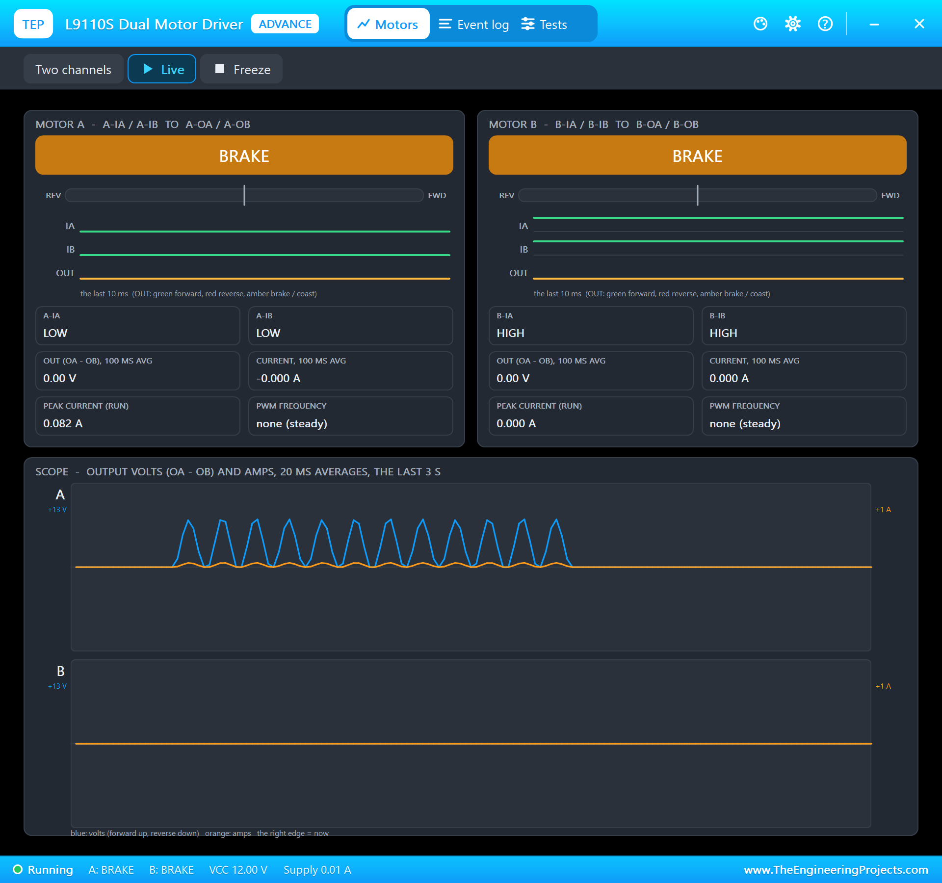
The driver's own pop-up shows the other side: motor A switching between FORWARD for each pulse and BRAKE in between, and its scope drawing the 12 V pulses on the coil. Between them, the two pop-ups show the whole chain from the sketch to the drums.
How the Model Works
The coil is in the circuit as a flux-linkage companion over the analog step - a conductance and a source - whose inductance follows the armature, so the driver sees the real load: 144 ohm, 220 mH with the armature out and 400 mH with it in, and the resistance rising with the coil's temperature. Between two analog points the armature runs in small steps: the magnetic pull of the current against the spring, the armature's mass and its damping. The analog step is held to 100 microseconds during a pulse or while the armature moves, and to 2 ms at rest. The same coil model drives our 12V Push-Pull Solenoid Library for Proteus.
The watch decides what a pulse is from the drive itself: a quarter of the rated voltage or more across the coil, with the power going in. A count is a close to 97 % of the travel followed by a return under 10 %, and every pulse that ends without one is named: too short, too weak, or back too soon. The same watch catches a coil held on, a kick of more than twice the rating when the coil is switched off without a diode, too much current, and the coil's temperature from its duty.
We checked the model on a PC with 28 automatic tests: a 12 V coil takes 83.3 mA and pulls in from 54.8 mA; ten pulses of 50 ms give ten counts with a pull-in of 16.4 ms and a release of 22.1 ms; 4 ms pulses are all missed; a 6 V supply is too weak while 9.5 V counts; 4 ms pauses lose nine counts in ten; the fastest clean rate is 18.5 a second; a coil held for two seconds counts once on the release; switched off without a diode the coil kicks to -320 V and the warning comes; a 24 V counter counts on 24 V; 999998 plus 3 is 000001. The demo project is read back from disk with 57 checks.
Troubleshooting
- It does not count and nothing is logged: no coil current - the L9110S has no 12 V, or its inputs are not driven.
- "MISSED - ... under the 55 mA pull-in": the supply is too low for the coil - a 24 V counter on 12 V, or a weak transistor.
- "MISSED - a ... ms pulse": the pulses are too short; give it 30 ms or more.
- "MISSED - the coil came back ... after the release": the pauses are too short; the armature needs about 22 ms to get back out.
- It counts only when the pulse ends: that is how impulse counters work - the count comes on the release.
- "the coil kicked to ... V": put a free-wheel diode across the coil.
- No driver in Pick Devices: install our L9110S library (
TEPL9110S.LIB/TEPL9110S.DLL). - No counter, no UNO or no monitor:
TEPEMCOUNT.DLLorTEPARDUINO.DLLis missing from MODELS and the project folder; a closed monitor opens again with a click on the UNO's USB port.
Things to Know Before Using a Real Impulse Counter
- Never from a pin: a 12 V counter takes 50 - 100 mA - use an NPN transistor or a logic MOSFET with a 1N4007 free-wheel diode across the coil, a relay, or an H-bridge.
- Pulse and pause: 30 - 50 ms on and at least as long off. The data sheet gives the most counts a second, often 10 - 25.
- Mind the polarity: some counters have the diode inside; then + must go to the positive side.
- Keep your own total: the counter knows nothing about your sketch. Keep the count in the program and reset or preset the drums by hand to match it.
Limitations of the Simulation
- Not modelled: contact bounce of a driving switch, a counter's own diode or varistor, the wear of the ratchet, and counters with an electronic display.
- The plate, the COIL LED, the rating line and the strip are TEP additions.
- The model is our own, written from the typical data of 12 V DC impulse counters; this library is not made or endorsed by any counter maker, Arduino or Labcenter.
- Licences: the demo HEX contains the Arduino AVR core 1.8.6 (LGPL); the sketch is included and the README gives the source link. The L9110S driver is our separate library.
- Tested in Proteus 8.5 in October 2026 with the demo as shipped: the knob, the burst, the short and fast pulses, held in, the rollover, the RESET and preset, all four pages of the pop-up and the driver's pop-up. Proteus 7 is not supported.
So, that was all about the Electromechanical Counter Library for Proteus V1.0. I hope it helps you build the counter you have in mind - a production tally, a visitor counter or a coin meter for your arcade cabinet - and saves you from the counts that quietly go missing. If you have any questions, ask in the comments and I will help you out. Till the next tutorial, take care and have fun!