Hello friends, I hope you all are doing great. Today, I am going to share the new DIP Switch Library for Proteus. A DIP switch is the little row of tiny slide switches you find on routers, garage door remotes, old sound cards, industrial controllers and countless development boards. Each slider is a small on or off setting, and together they make a number: an address, a channel, a mode. Set it once with a pen tip, and the circuit knows what to do every time it powers up.
DIP Switch Library for Proteus
Latest version: V1.0 (November 2026, this tutorial)
Other component libraries: C945 Transistor · PC817 Optocoupler · Relay Module · Resistor · 5 mm LED · Designer Colour LED · Push Button · Active Buzzer · Electrolytic Capacitor · Ceramic Capacitor · Tantalum Capacitor · Film Capacitor · 1N4007 Diode · Zener Diode · Schottky Diode · Supercapacitor · Photodiode · RGB LED · Bridge Rectifier · Flashing LED · Bi-Colour LED · SMD LED · Slide Switch · Toggle Switch · Rocker Switch · Micro Limit Switch · Emergency Stop Switch · SMD Resistor · Power Resistor · Resistor Network · Potentiometer · Trimmer Potentiometer · Slide Potentiometer · NTC Thermistor · Fuse · Passive Buzzer · Mini Speaker · 7-Segment Display · LED Bar Graph · IR / UV LED · Small Transistors · TIP122 Darlington · N-MOSFET · P-MOSFET · PC817 Optocoupler · Filament Bulb · Power LED · Voltage Regulator · SCR and TRIAC · Inductor · Toroid Inductor · Crystal
Helping Tools
- Serial Monitor Advance: a serial terminal window for the UART of your board
- Serial Monitor Expert: the serial monitor with extra debugging tools
- LCD Library for Proteus V3.0: 16x2, 20x4 and I2C LCDs to show your readings
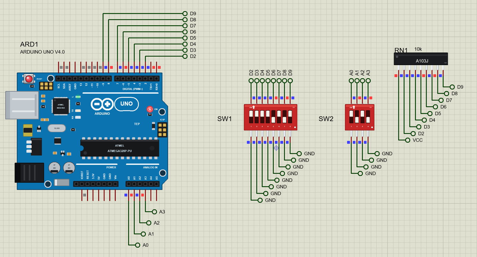
Our library has the two sizes you will meet most often, at true scale: an 8-way switch and a 4-way one, in the classic red body with white sliders and ON printed at the top. At Run, you click a slider and it flips, and the sliders stay exactly where you left them after Stop, just like a real switch on a real board. The pop-up shows the value in binary, decimal and hex, and the current through every contact. The demo reads both switches as numbers, with our resistor network as the pull-ups.
NOTICE: Our team has put a lot of effort into these small parts: the bodies, the animation and the pop-ups are all our own design, and you get them free. Your feedback is the fuel that keeps us going, so please tell us what you think in the comments below or in the DIP Switch board of our forum. And if our free libraries help you, you can buy us a coffee. So, let's get started with the DIP Switch Library for Proteus:
What is a DIP Switch?
A DIP switch is a set of small switches in one package. DIP stands for Dual In-line Package, the same body shape as the classic through-hole chip: two rows of pins, 2.54 mm apart along the row and 7.62 mm between the rows. Each switch is a simple SPST contact. On our parts, switch 1 joins pin 1 to the pin facing it in the other row, switch 2 joins pin 2 to its neighbour across, and so on. Slide it towards ON and the contact closes; slide it back and it opens.
The most common styles are the slide type, with a small lever in each window, and the piano type, with keys that rock sideways. Our parts follow the CTS 206 series of slide switches, the shape almost everyone pictures. They are made for setting, not for everyday switching: a few thousand moves over the life of the product, and a small current, 50 mA at 24 V for the CTS parts.
| Feature | The 8-way | The 4-way |
|---|---|---|
| Style | CTS 206-8, slide | CTS 206-4, slide |
| Body | 22.5 mm long, red | 12.2 mm long, red |
| Pins | 16, rows 7.62 mm apart | 8, rows 7.62 mm apart |
| Rating | 50 mA at 24 V | 50 mA at 24 V |
| In the library | 945 thou long, true scale | 512 thou long, true scale |
A Row of Bits
Each slider is one bit: ON or OFF, 1 or 0. Four sliders give 16 combinations, eight give 256. In our library and in our sketch, switch 1 is the lowest bit, so switch 1 is worth 1, switch 2 is worth 2, switch 3 is worth 4, and switch 8 is worth 128. Add up the values of the switches that are ON, and you have the number. Switches 1, 3, 4 and 6 ON make 1 + 4 + 8 + 32 = 45, which is 0x2D in hex.
| Switches ON | Binary (8 .. 1) | Decimal | Hex |
|---|---|---|---|
| 1, 3, 4, 6 | 00101101 | 45 | 0x2D |
| 1, 3, 4, 6, 8 | 10101101 | 173 | 0xAD |
| 1, 2, 3, 4, 6, 8 | 10101111 | 175 | 0xAF |
| all eight | 11111111 | 255 | 0xFF |
Hex in Groups of Four
Hexadecimal is the easiest way to say what a DIP switch is set to. Every hex digit stands for exactly four switches: the right digit for switches 1 to 4, the left digit for switches 5 to 8. So 0x2D splits into 2 (switches 5 to 8: only switch 6 ON) and D, which is 13 (switches 1 to 4: 1, 3 and 4 ON). With a little practice you can read the sliders straight off as hex, which is why so many manuals give DIP settings that way.
Pull-Ups
A switch only closes or opens a contact; it does not make a voltage by itself. To read it, the usual way is to tie one side of each switch to ground and the other to an input, with a pull-up resistor from that input to the supply. Open, the pull-up holds the input HIGH. Closed, the switch pulls it to ground, LOW. So with pull-ups, ON reads LOW, and the sketch turns that LOW into a 1.
The pull-ups can come from separate resistors, from a resistor network with its common pin on the supply, or from the microcontroller itself. The Arduino can turn on an internal pull-up on any input with INPUT_PULLUP. Our demo uses both ways, so you can see the difference.
Choosing the Pull-Up
A 10k pull-up is the usual choice. With the switch ON, it lets 0.5 mA flow from 5 V to ground, which is small but still strong enough to hold the input firmly HIGH when the switch is OFF, even with a few centimetres of wire picking up noise. The Arduino's internal pull-ups are much weaker, between about 20k and 50k on a real chip, which saves current but makes the inputs easier to disturb on long wires. For a switch on the same board as the microcontroller, either is fine.
Slide, Piano or Rotary
Besides the slide type in our library, there are piano DIP switches, whose keys stick out of the side and rock up and down, handy when the board stands on its edge. Rotary DIP switches, also called code switches, turn an arrow to one of 10 or 16 positions and give the number directly as four bits. There are surface-mount versions too, and sealed ones with a peel-off tape, so the board can be washed after soldering without dirt getting inside.
Read Once at Power-Up
Most products read their DIP switches once, in setup, and then use the value for as long as they run. A new address, for example, often takes effect only after a reset, so the device never changes its identity in the middle of a conversation. Our demo reads the switches all the time, which is better for learning: every click shows up on the monitor at once.
Where They Are Used
DIP switches set the address of a device on a bus, such as an I2C board or a Modbus node, so several identical boards can share one line. They set the channel of a radio or a garage door remote, the mode of a controller, the baud rate of a serial device, and the options of a development board. Anything chosen once and rarely changed is a good job for a DIP switch.
Features of the DIP Switch Library for Proteus
- The real look, at true scale: red bodies with white sliders, ON and the numbers printed, two rows of pins, and our small TEP signature.
- Click a slider to flip it: at Run, a click on a slider flips that switch.
- Kept after Stop: every combination is a ready-drawn picture, so the sheet shows the sliders while stopped and keeps them after Stop.
- Real contacts: 50 milliohm closed, open otherwise, with a 50 mA rating and a warning past it.
- A pop-up for every switch: the value in binary, decimal and hex, the switch drawn large, every contact's current, graphs, an event log and a check page.
- Chips: flip any switch, All on, All off, Invert, and Count, which runs it up in binary.
- A complete package: about 1.6 MB with the library, our Arduino UNO V4.0, our resistor network and the demo, without the source code of the models.
The DIP Switches in Proteus
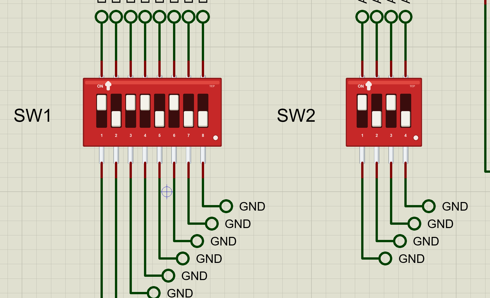
The devices are DIPSWITCH8TEP and DIPSWITCH4TEP in TEPDIP.LIB, under Switches and Relays, Switches, with the prefix SW and the model TEPDIP.DLL. Search DIPSWITCH in Pick Devices. The bottom row holds pins 1 to N from the left; the top row holds the pins facing them.
The Properties
| Property | What it does |
|---|---|
| Contact resistance, ohm | 0.05: each closed contact |
| Contact rating, mA | 50: past it the pop-up warns |
| Sliders while stopped | the sliders as a number, bit k-1 for switch k: set by clicking at Run |
Download DIP Switch Library for Proteus
Click the button below to download DIP-Switch-Library-for-Proteus-v1.0.zip (about 1.6 MB, without the source code of the models):
DIP Switch Library for Proteus V1.0- README.txt: installation, the demo, the properties, troubleshooting and the limits.
- Proteus Library Files:
TEPDIP.LIB,TEPRESNET.LIBand ourArduinoV4TEP.LIB. - Proteus Model Files:
TEPDIP.DLL,TEPRESNET.DLLandTEPARDUINO.DLL. - Arduino Code: the demo sketch.
- Proteus Simulation: the demo project, its HEX file and copies of the DLLs.
No Proteus yet? Read How to Download and Install Proteus 7 and 8. New to libraries? Follow How to Install a New Library in Proteus.
How to Install DIP Switch Library for Proteus
- Close Proteus and extract the whole zip file, for example to your Desktop.
- Copy the files from Proteus Library Files into the LIBRARY folder of Proteus.
- Copy the files from Proteus Model Files into the MODELS folder.
- Delete
TEPDIP.IDXfrom the LIBRARY folder if it is there. - Start Proteus, press P and search for DIPSWITCH.
Demo: Reading DIP Switches as Numbers
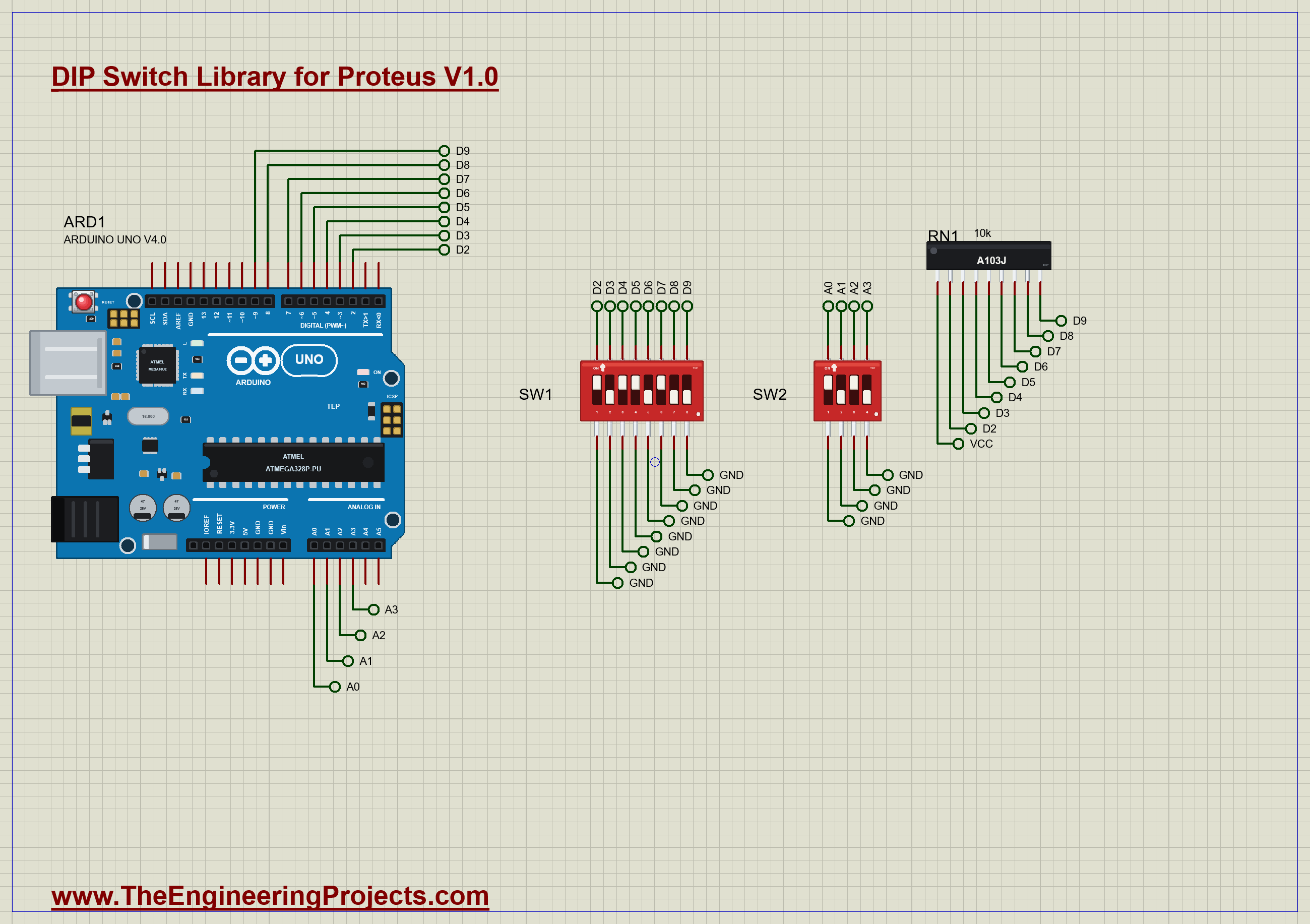
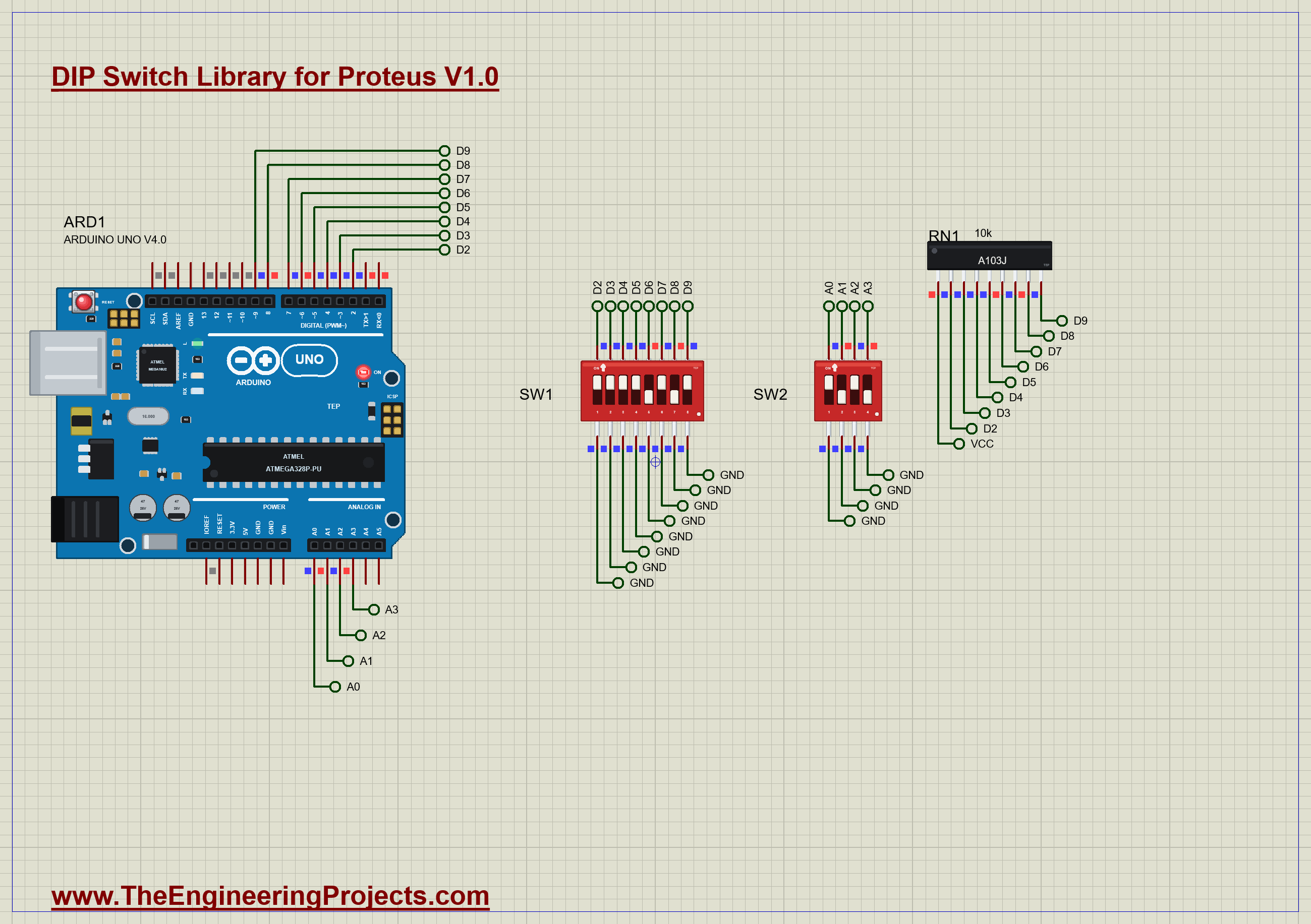
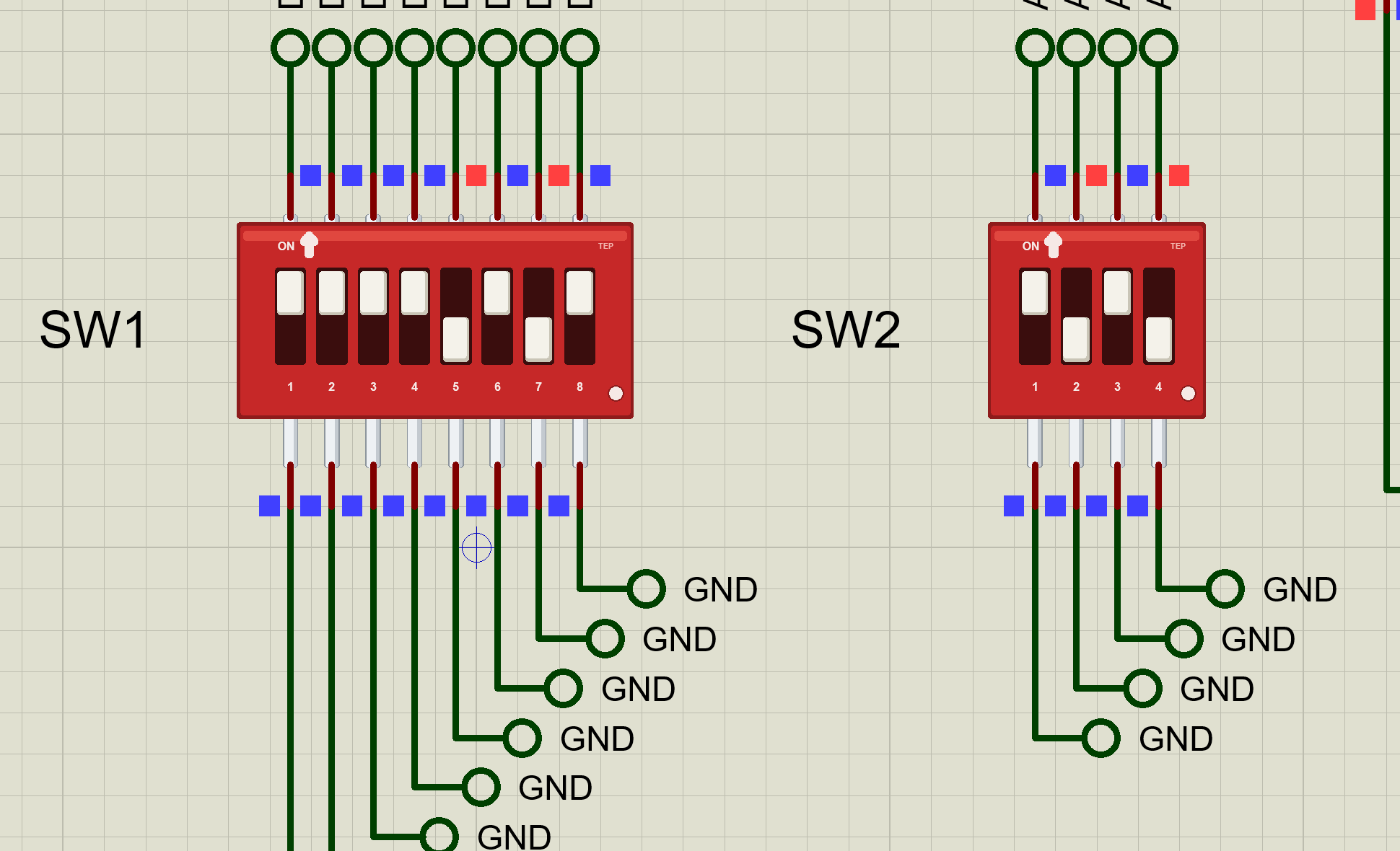
SW1, the 8-way switch, has its bottom row on ground and its top row on D2 to D9, switch 1 on D2. RN1, a SIP-9 network printed A103J, holds those eight inputs up to 5 V through 10k each: eight pull-ups in one part. SW2, the 4-way switch, is wired the same way to A0 to A3, but with the UNO's own internal pull-ups. Open DIP-Switch-Reader-ArduinoUnoV4.pdsprj. It runs on our Arduino UNO Library for Proteus V4.0, with its built-in monitor, the same window as our TEP Serial Monitor Advance for Proteus. The network is from our Resistor Network Library for Proteus.
| Part | Connection | Job |
|---|---|---|
| SW1 (8-way) | bottom row GND, top row D2 .. D9 | the 8-bit value |
| RN1 (SIP-9, A103J) | pin 1 +5V, pins 2 .. 9 to D2 .. D9 | eight 10k pull-ups |
| SW2 (4-way) | bottom row GND, top row A0 .. A3 | a mode, 0 .. 15 |
The Sketch
The inputs of SW1 are plain inputs, because RN1 pulls them up. The inputs of SW2 use the UNO's own pull-ups:
  for (byte k = 0; k < 8; k++) pinMode(SW1_FIRST + k, INPUT);
  for (byte k = 0; k < 4; k++) pinMode(SW2_PIN[k], INPUT_PULLUP);
Reading a switch is then a loop over its inputs. A LOW means ON, and switch k becomes bit k - 1 of the value:
byte readSw1() {
  byte v = 0;
  for (byte k = 0; k < 8; k++)
    if (digitalRead(SW1_FIRST + k) == LOW) v |= 1 << k;
  return v;
}
The loop prints both values whenever either changes, in binary, decimal and hex.
Run the Demo
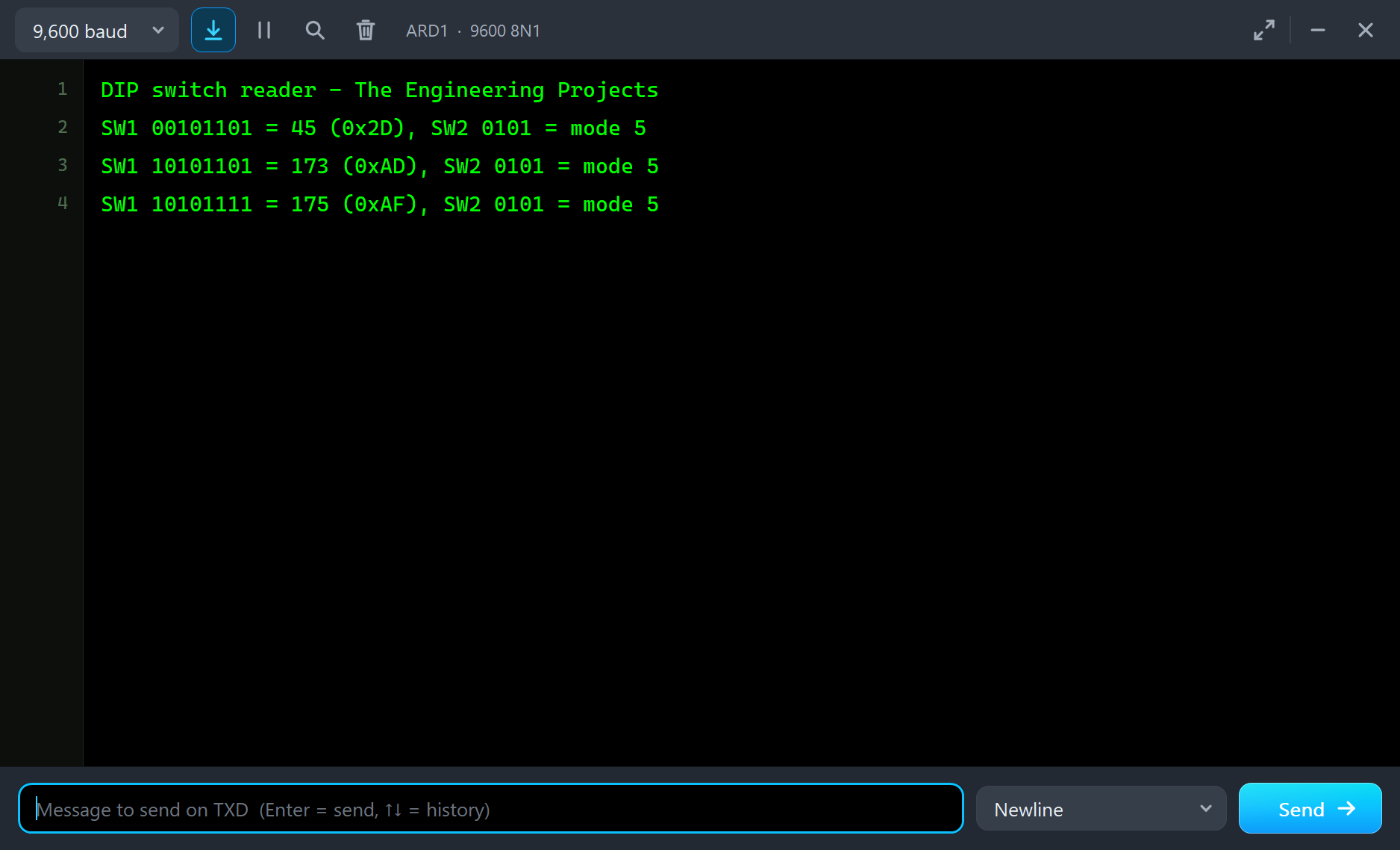
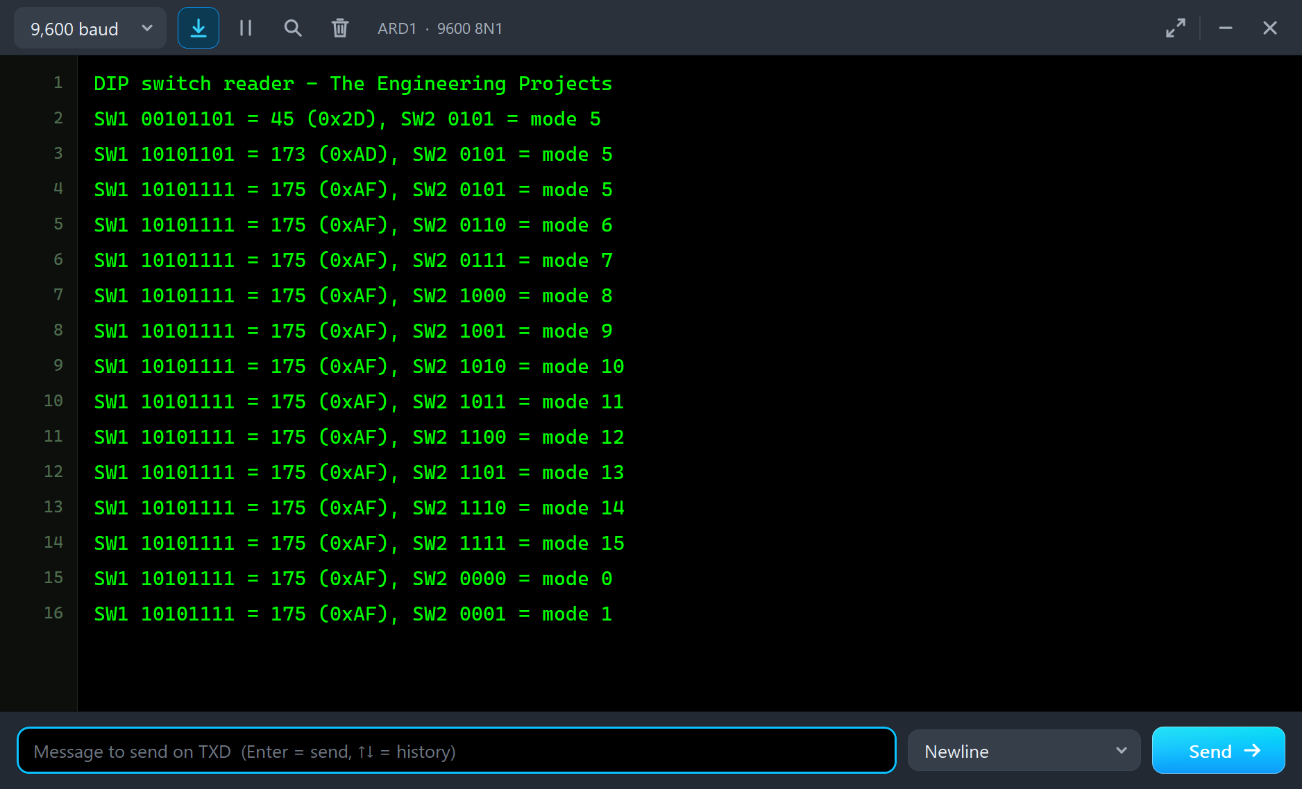
Press Run. SW1 starts with switches 1, 3, 4 and 6 ON, and SW2 with switches 1 and 3. The monitor prints them at once: SW1 00101101 = 45 (0x2D), SW2 0101 = mode 5:
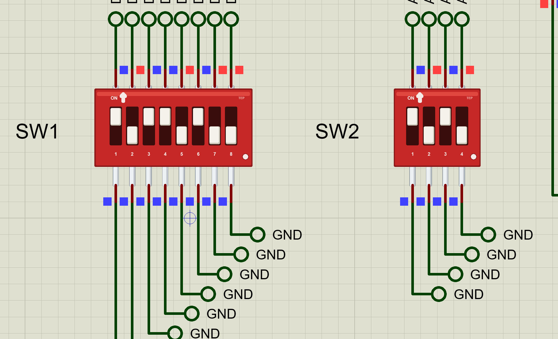
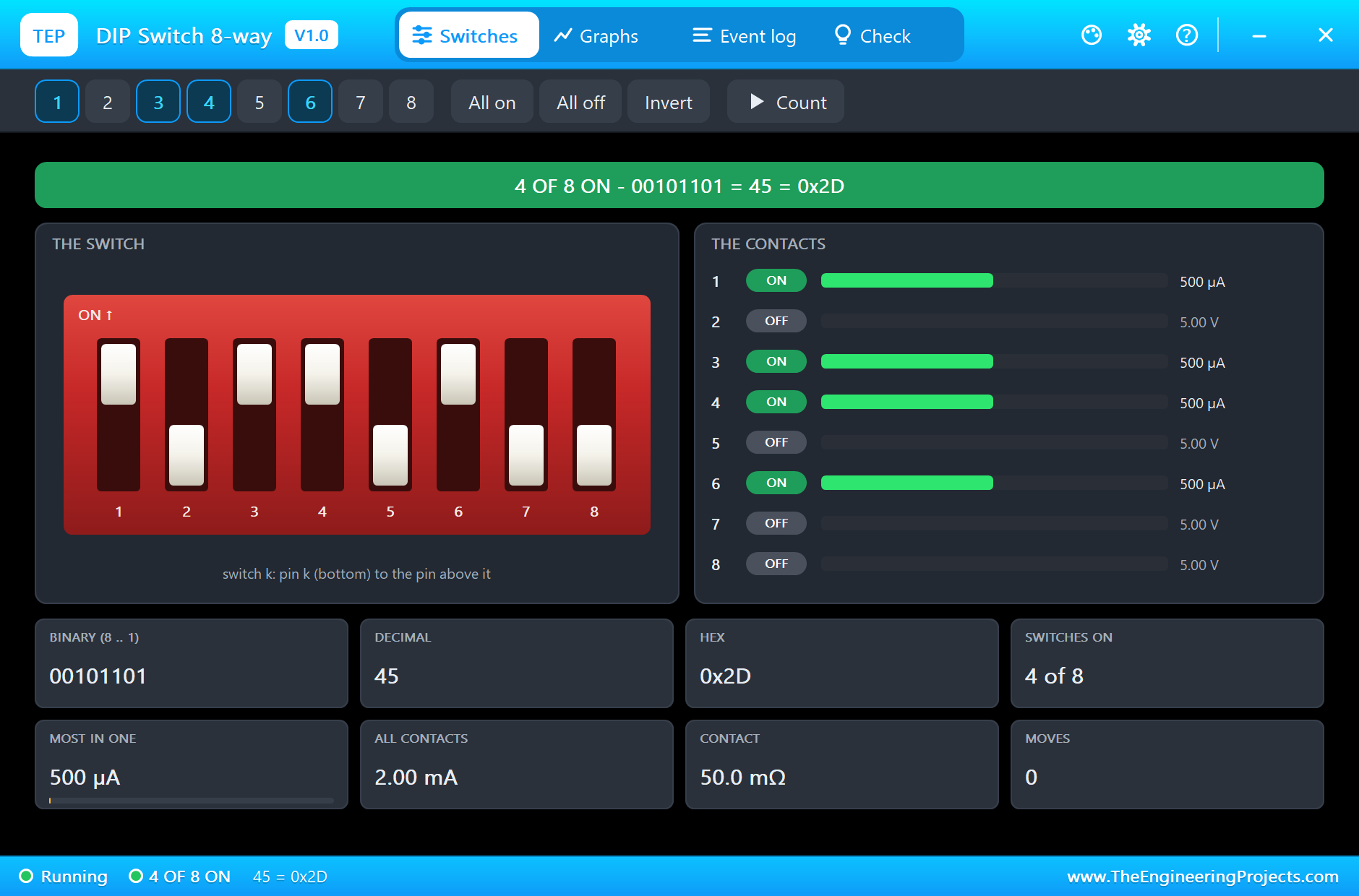
Click the small dot on SW1 to open its pop-up. The banner reads 4 of 8 ON, and the contacts card shows 0.5 mA through each closed switch: 5 V across its 10k pull-up. The open ones have the full 5 V across them:
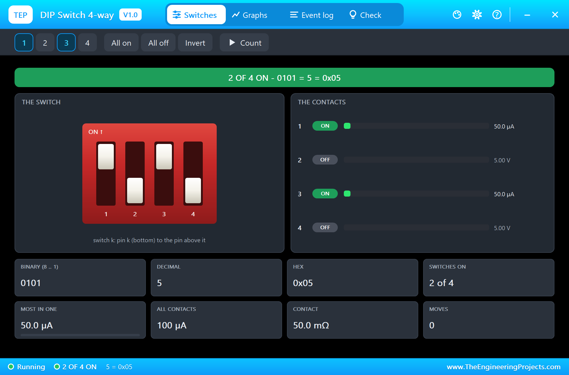
SW2's pop-up tells a different story. Its pull-ups are the UNO's own, which are much weaker than 10k, so its closed switches carry only about 50 µA each:
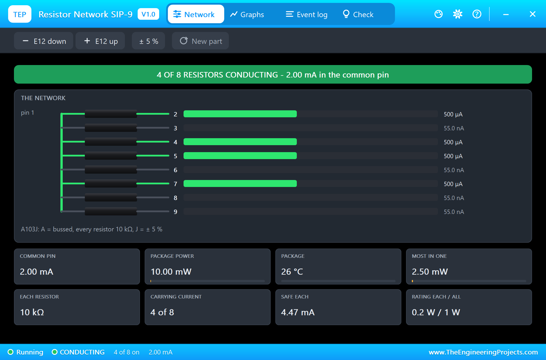
And RN1's own pop-up shows the same currents from the other side: one 0.5 mA bar for every switch that is ON, and nothing for those that are OFF:
Flipping Switches
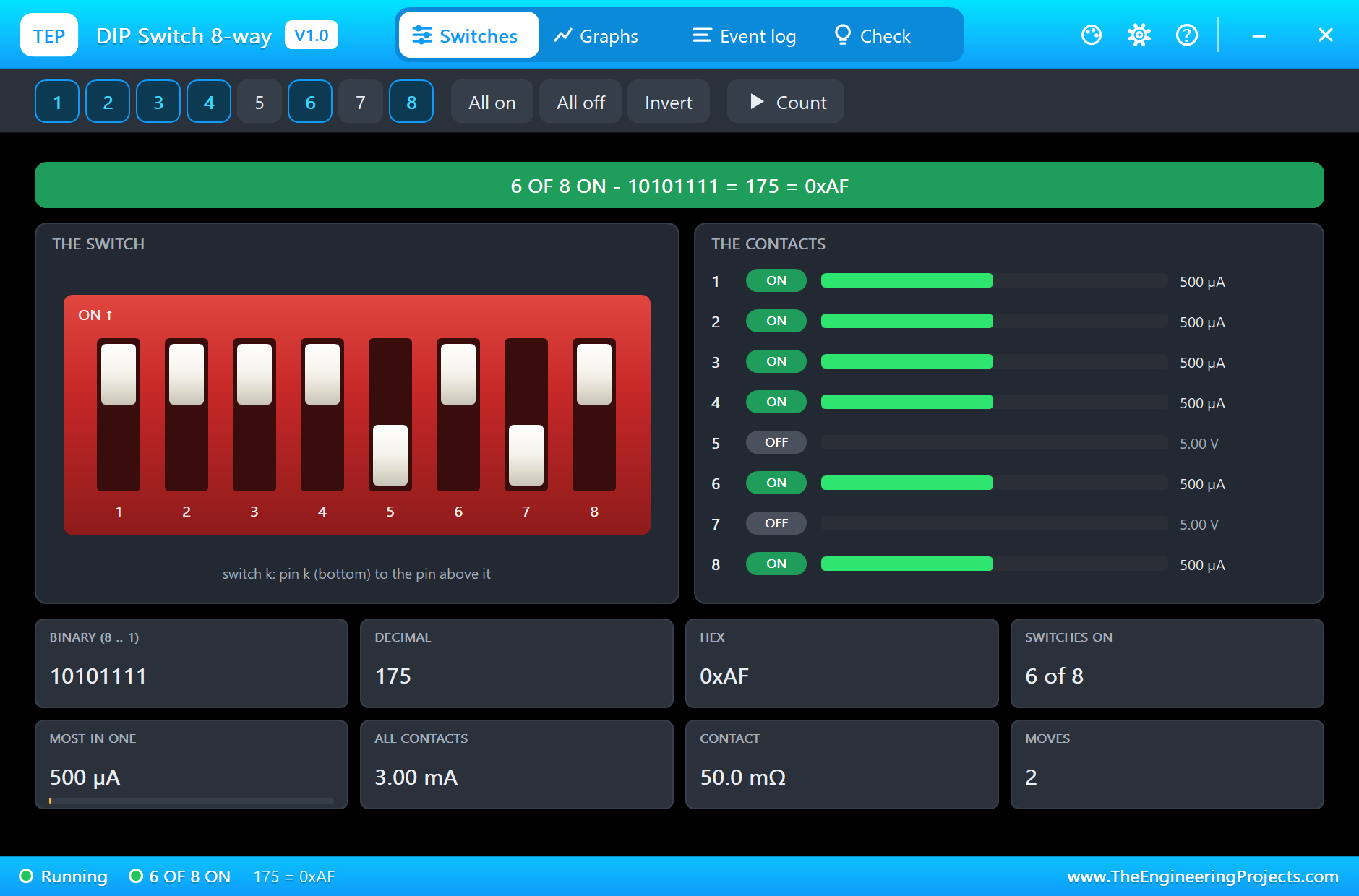
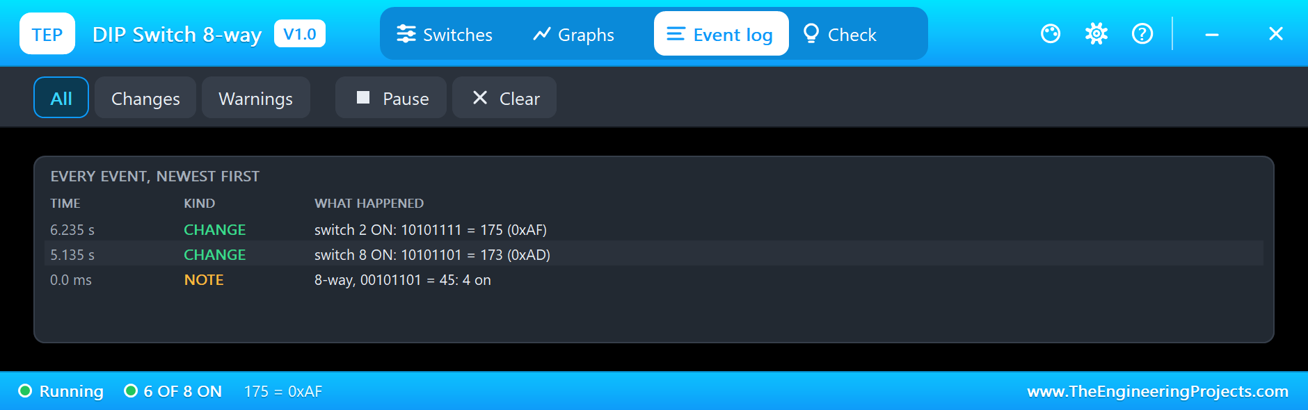
Now flip switch 8 and then switch 2, with the numbered chips on the pop-up or by clicking the sliders on the sheet. The value goes to 173 (0xAD), then 175 (0xAF). Six contacts are now closed, and the network carries 3.00 mA in all. Here is the complete circuit, truly running:
Counting in Binary
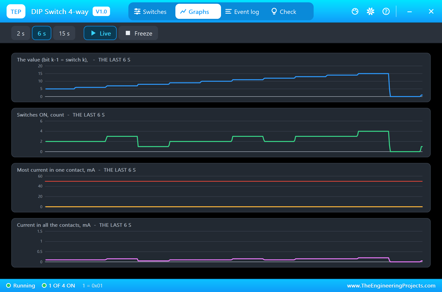
The Count chip runs a switch up through every value, one step every half second, exactly like a binary counter. On SW2 it goes from 5 through 15, wraps to 0 and starts again. The Graphs page draws it as a staircase, and the monitor prints every step:
The Log and the Check Page
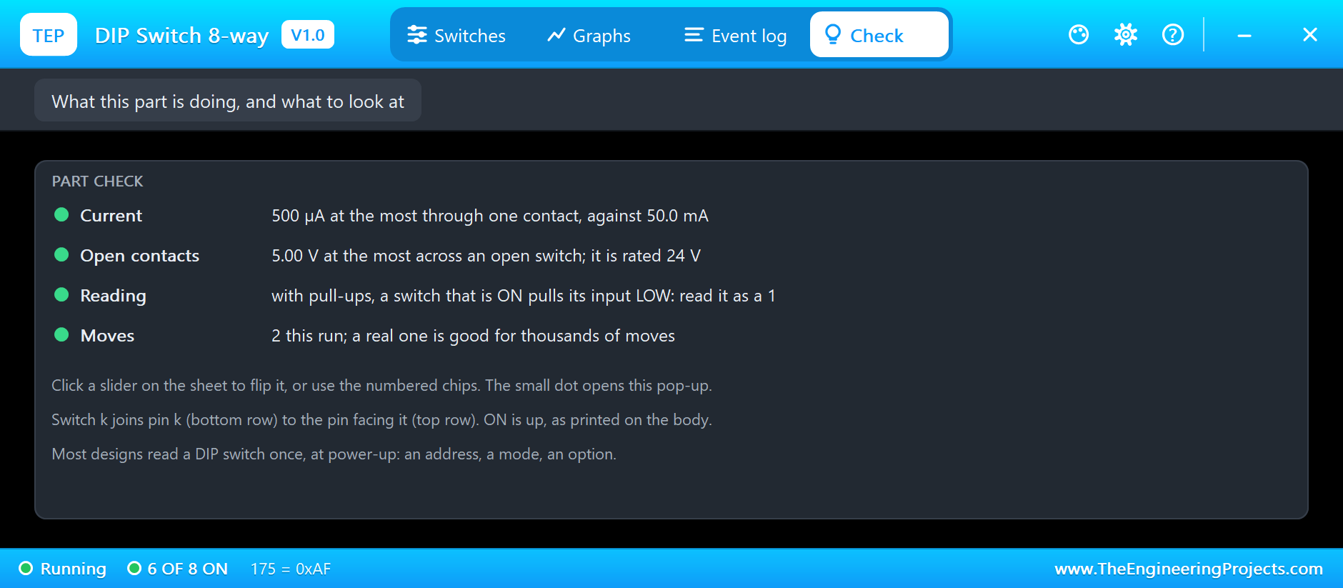
The Event log names every switch that moved, with the new value. The Check page compares the current with the 50 mA rating, the voltage across the open contacts with 24 V, and explains how the pull-ups turn ON into a LOW:
Clicking a Slider
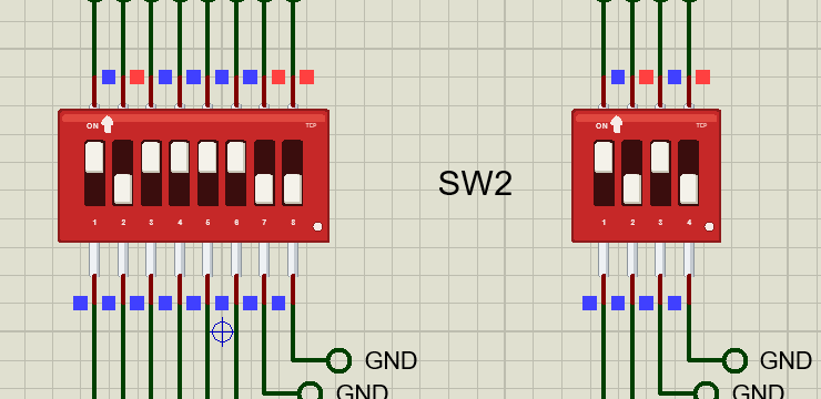
We tested the sliders with a real mouse. One click on switch 5 of SW1 flipped it ON, and the value went from 45 to 61 at once; a click on the small dot in the corner opened the pop-up instead:
Try It Yourself
- Set SW1 to your birthday as a number from 1 to 31, and read it back in binary.
- Turn every switch of SW1 ON, and check the total current on RN1's pop-up.
- Remove INPUT_PULLUP from the sketch, and watch SW2 stop working.
- Use SW2's mode to choose one of four blink patterns on an LED.
- Click Invert on SW1, and see how the value relates to 255 minus the old one.
Ideas to Extend the Demo
- Use SW1 as the I2C address of a sensor board, and SW2 to choose its options.
- Read the switches only once, in setup, the way most real products do.
- Show the value on a 7-segment display.
- Save power by turning the pull-ups on only while reading.
Your Own Sketches
The demo sketch is in the zip file, and you can change it in the Arduino IDE. New to Arduino? Start with our Arduino Tutorial for Beginners. Export the compiled binary, and set the UNO's PROGRAM property to the new file. Our guide on How to get the HEX file from Arduino shows you where the file ends up.
Things to Know Before Using a Real DIP Switch
- Check which side is ON: it is printed on the body; get the rows right before you lay out the board.
- Use pull-ups: resistors, a network, or INPUT_PULLUP; a floating input reads nonsense.
- Keep the current small: 50 mA at the most, and far less with pull-ups.
- Move them gently: use a pen tip or a small screwdriver; the sliders are tiny.
- Read once, if you can: most designs read a DIP switch at power-up only.
Troubleshooting
- A switch reads backwards: with pull-ups, ON pulls the input LOW. Read a LOW as a 1.
- Every input reads 1 with all switches off: that is correct with pull-ups and no inversion; invert in the sketch.
- Inputs read at random: the pull-ups are missing.
- A click does nothing: the simulation is not running, or the click missed the slider; the rest of the body opens the pop-up.
- The part is not simulated:
TEPDIP.DLLis missing from MODELS and from the project folder.
Limitations of the Simulation
- Contact bounce is left out: a real slider bounces for a millisecond or so.
- Wear and the slide force are not simulated.
- Piano-style DIP switches are not included.
- Arduino is a name of Arduino; this library is not made or endorsed by Arduino or Labcenter.
- Tested in Proteus 8.5 in November 2026 (the demo as shipped). Proteus 7 is not supported.
So, that was all about the DIP Switch Library for Proteus. I hope it helps you give your projects an address, a channel or a mode, set with a single click. If you have any questions, ask in the comments and I will help you out. Till the next tutorial, take care and have fun!