Speed Control of DC Motor using PIC Microcontroller


Many applications in industry such us robotics controls, swing machines, electronic bikes, winding machines, Spinning and Weaving machines and many others applications need a variable speed of DC motor. The best method for speed control of DC motor is the use of Pulse Width Modulation technique. This is a method to control the output voltage with the of constant frequency switching and by adjusting on duration of switching and in other words by changing duty cycle of switching.
Speed Control of DC Motor using PIC Microcontroller
- You can download the complete Proteus Simulation along with the Programming Code in MikroC Pro for PIC Compiler for Speed Control of DC Motor by clicking the below button:
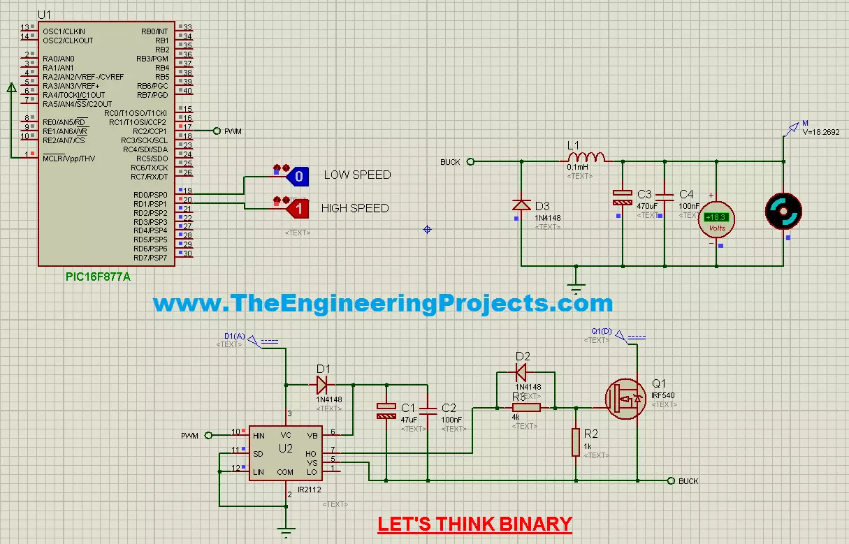
- The scheme of the project is given in the circuit below :

- Where :
- CONTROL STAGE : The microcontroller is PIC16F877A
- POWER STAGE : BUCK structure : L, C, D, MOSFET
- INTERFACE STAGE : IR2110
- Now in the above project, I have used IR2110 using which I have controlled the speed of DC Motor.
- You can see the PWM pin of PIC Microcontroller is coming to IR2110.
- Mr. Salah has designed the code in MikroC Pro for PIC compiler and the code is given below:
unsigned short current_duty1, current_duty2,dt;

void main()
{
  ADCON1 |= 6;                    // all ports as digital
  CMCON  |= 7;                  // comparators off
  TRISD = 0X03;
  PORTD=0;

 PWM1_Init(5000);                     // Initialize PWM module at 5KHz
 PWM1_Start();                       // start PWM1

 while (1) {                         // endless loop

    if (RD0_bit==1 && RD1_bit == 0)           // button on RD0 pressed
      {
      Delay_ms(40);
      //current_duty1=127;                 // Set duty ratio to 50%
      current_duty1=64;                 // Set duty ratio to 25%
                                         //   duty ratio can be calculated as (Percent*255)/100
      PWM1_Set_Duty(current_duty1);
      }
    else if (RD1_bit==1 && RD0_bit == 0 )     // button on RD1 pressed
      {
      Delay_ms(40);
      //current_duty1=192;                 // Set duty ratio to 75%
      current_duty2=216;                   // Set duty ratio to 85%
                                          //   duty ratio can be calculated as (Percent*255)/100
      PWM1_Set_Duty(current_duty2);
      }
     else
      {
       Delay_ms(40);
      dt=0;
      PWM1_Set_Duty(dt);

      }
     Delay_ms(10);                      // slow down change pace a little
   }
 }
- In the above code, you can see he has used the PWM to do the speed control the DC Motor.
- Few of important commands used in above code are given below:
-
- PWM1_Init(constant long frequency) : This function initializes the PWM module with duty ratio 0. Frequency parameter is the desired frequency in Hz. It should be a numeric constant, should not be a variable.
- PWM1_Set_Duty(unsigned short duty_ratio) : This function is used to set the duty cycle of the PWM. The parameter duty_ratio takes values from 0 to 255, ie 0 means 0% , 127 means 50% and 255 means 100% duty cycle. The PWM1_Init() routine must be called before using this.
- PWM1_Start() : This function starts the PWM output. PWM1_Init() must be called before calling this routine,
- PWM1_Stop() : This function stops the PWM output. PWM1_Init() must be called before calling this routine. PWM1_Start() should be called before calling this function otherwise calling this function will not have any effect as PWM module is not running.
- When you run your simulation then in High speed it will look something as shown in below figure:
- As you can see in the above figure that the voltage across DC Motor is around 18V and if you are running the simulation then you will see the motor will be moving quite fast.
- Now let's move our motor in slow speed, in order to do that you have to turn ON Low speed switch as shown in below figure:
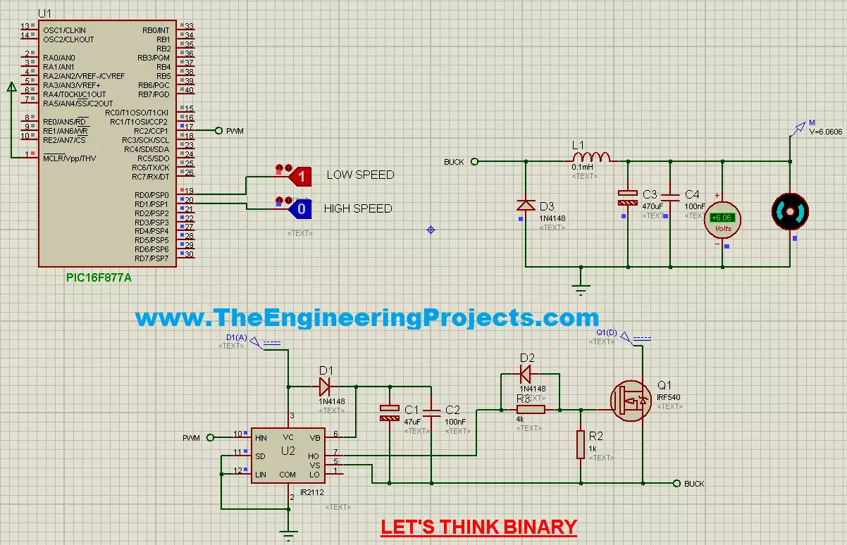
- Now if you check the voltage across DC Motor then you can see its 6V and the Dc Motor will now move at slow speed.
- Here's the video for the above project which will give you better idea of How it works:
That's all for today, thanks for reading Speed Control of DC Motor using PIC Microcontroller. I hope you have enjoyed this tutorial. In the end, I again wanna thanks to my dear friend Salah Dahouathi who has spend time in designing this great simulation, programming code and tutorial. You should also like his Facebook Group where he keeps on posting such Arduino related projects, name of his Facebook group is Let's Think Binary. So, will see you guys in next tutorial, till then take care and have fun !!! :)