


What Is a Voltage Follower and How Is It Different from a Buffer?


In the context of electronics and circuit layout, signal integrity and competent power transfer are important for confirming proper system implementation. Engineers continually use circuit compositions that isolate phases, match impedance, and keep signal characteristics. Among these structures, the voltage follower and the buffer are broadly utilized ideas. However, these two conditions are usually utilized conversely, but they are not consistently identical. Comprehending the fine distinctions between them is critical for scholars, architects, and developers operating with digital and analog systems.
A voltage follower is a typical type of circuit, generally executed by operating an operational amplifier, that supplies harmony gain while suggesting high input impedance and low output impedance. A buffer, on the other hand, is a more comprehensive idea guiding any circuit that separates two phases of a system, controlling signal contortion or loading outcomes. What is voltage follower? It is a typical question in electronics that directs to an op-amp circuit where the output voltage directly follows the input voltage with unity gain.

Expert’s Insight:
“A voltage follower is an operational amplifier circuit whose output voltage follows the input voltage with unity gain.”
Source: https://en.wikipedia.org/wiki/Voltage_follower
1. What Is a Voltage Follower?
A voltage follower, also understood as a unity-gain amplifier, is a circuit arrangement in which the output voltage instantly obeys the input voltage. In simple words:
Output Voltage = Input Voltage
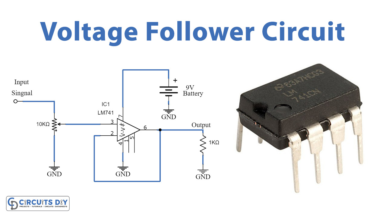
This composition is generally executed using an operational amplifier. The input signal is connected to the non-inverting terminal, while the output is directly connected back to the inverting terminal, forming a response circle.
Essential Factors of a Voltage Follower:
- High Input Impedance: It illustrates a very small current from the origin.
- No Phase contradiction: The output signal is in phase with the input.
- Unity Gain: The output voltage is equivalent to the input voltage.
- Low Output Impedance: It can cause loads to operate efficiently.
- Isolation: Controls the loading effect between stages.

2. Working Principle of a Voltage Follower:
The operation of a voltage follower is founded on an unfavourable response. When an input voltage is used:
- The result is a response to the inverting terminal.
- Thus, the output voltage is equivalent to the input voltage.
- The op-amp tries to amplify the distinction between its input terminals.
- The op-amp modifies its output unless both input terminals are at the same voltage.
This response mechanism provides resilience and proper signal tracking.
3. Why Use a Voltage Follower?
Voltage followers are utilized especially for impedance matching and signal buffering. It has a very elevated input impedance and a very low output impedance. High input impedance guarantees that the circuit sketches minimal current from the signal source, thereby controlling loading outcomes. Low output impedance permits the circuit to operate loads efficiently without an important voltage reduction. This assortment makes the voltage follower model for interfacing between circuits with incompatible impedance levels.
They are particularly beneficial when:
- You want to control signal loss due to loading.
- You need to isolate various components of a circuit.
- A high-impedance signal source is required to drive a low-impedance load.

4. Applications of Voltage Followers:
Voltage followers and buffers play a crucial role in advanced electronic systems by guaranteeing that signals are transmitted properly between different circuit phases without distortion or loss. One of the most typical applications of a voltage follower is in detector interfacing, where invalid signals from sensors need to be maintained while operating other features, such as analog-to-digital converters. Voltage followers are widely utilized in different electronic systems:
- Sensor Interfacing
- Audio Systems
- Sample-and-Hold Circuits
- Analog-to-Digital Converter Inputs
- Signal Conditioning Circuits
- Voltage Reference Circuits
5. What Is a Buffer?
A buffer is a multi-purpose circuit designed to transmit a signal from one stage to another without altering its components. Its major objective is to isolate circuits and prevent unwanted exchanges. Buffers, in a more general sense, are utilized in both analog and digital electronics to isolate various parts of a system and enhance signal integrity. In digital circuits, buffers enhance the driving ability of logic gates, permitting a single signal to maintain numerous outputs without weakening. Unlike a voltage follower, a buffer is not restricted to a distinctive layout. It can be implemented operating:
- Transistors
- Dedicated buffer ICs
- Operational amplifiers
- Digital logic gates
Expert’s Insight:
“A buffer amplifier is used to isolate stages of a circuit while preventing signal loading effects.”
Essential Factors of a Buffer:
- Impedance Matching
- Prevention of Loading Effects
- Signal Isolation
- Signal Integrity Preservation
- Current Amplification

6. Working Principle of a Buffer:
The buffer accepts an input signal and duplicates it at the output while controlling the load from impacting the source. Relying on the layout:
- It may supply current amplification
- It provides that the signal quality remains intact
- It may provide unity gain
7. Types of Buffer:
Buffers can be categorized into several types based on their performance and objective:
7.1. Analog Buffers:
An analog buffer is an electronic circuit utilized in analog systems to isolate various phases of a circuit while minimizing signal distortion and failure. It is specifically developed to transmit analog signals from a high-impedance authority to a low-impedance load without altering the actual signal’s voltage or waveform.
- Utilized in analog circuits
- Usually implemented utilizing op-amps
- Example: Voltage follower
7.2. Digital Buffers:
A digital buffer is utilized in digital circuits to maintain or renew logic signals, guaranteeing reliable communication over long distances or through numerous gates.
- Strengthen weak signals
- Provide fan-out capability
- Used in digital circuits
7.3. Current Buffers:
A current buffer raises the current-driving capacity of a signal without modifying its voltage level, generally utilized in power amplification stages.
- Used in power applications
- Maintain current levels
7.4. Voltage Buffers:
A voltage buffer, also understood as a voltage follower, strengthens the exact input and output voltage while supplying high input impedance and low output impedance, creating it perfect for impedance identical.
- Maintain voltage levels
- Provide impedance matching

8. Table of Key Differences Between Voltage Follower and Buffer:
| Header 1 | ||
|---|---|---|
| Feature | Voltage Followe | Buffer |
| Definition | Specific op-amp configuration | General circuit for signal isolation |
| Function | Replicates voltage | Isolates and strengthens signals |
| Output behaviour | Same as input | May modify current or drive capability |
| Feddback | Use negative feedback | May or may not use feedback |
| Gain | Unity (Gain=1) | Unity or greater than 1 |
| Complexity | Simple | Can be complex or simple |
| Implementation | Typically op-amp | Op-amp,trasnistors, or digital circuits |
| Usage scope | Narrow | Broad |
| Header 1 | ||

9. Key Difference :
The fundamental difference lies in particularity: a voltage follower is a typical type of buffer, whereas a buffer is an all-around operational classification. Every voltage follower works as a buffer because it isolates circuits and controls loading, but not every buffer is a voltage follower since buffers can function with additional functions like amplification or signal driving.
10. Table of Electric characteristics comparison:
| Header 1 | ||
|---|---|---|
| Parameter | Voltage follower | Buffer |
| Output impedance | Very low | Low |
| Voltage gain | 1 | 1 or more |
| Frequency response | Wide | Depends on implementation |
| Input Impoedance | Very high | High |
| Power consumption | Low | Varies |
| Current gain | Moderate | Can be high |
| Stability | High due to feedback | Depends on design |
| Header 1 | ||
11. Benefits of a Voltage Follower:
1. High Input Impedance:
A voltage follower has excessively high input impedance, which implies it attracts almost no current from the input source.
2. Signal Isolation:
It separates the input stage from the output stage. This guarantees that modifications in the load do not impact the input signal source, enhancing overall circuit resilience.
3. Improved Signal Integrity:
It diminishes distortion and controls loading impacts, which helps possess clean and authentic signal transmission.

12. Benefits of Buffer:
1. Prevents Loading Effect:
Buffers destroy the loading effect, which happens when a low-resistance load draws extreme current from a high-resistance source.
2. Signal Isolation:
One of the most significant benefits of a buffer is that it isolates the input and output stages. This controls the load from impacting the source circuit.
3. Prevents Loading Effect:
Buffers remove the loading effect, which happens when a low-resistance load draws excessive current from a high-resistance source.

13. When to Use a Voltage Follower vs a Buffer:
Use a Voltage Follower When:
- You want simple impedance matching
- You want minimal design complexity
- You need unity gain
- You are working with analog signals
Use a Buffer When:
- You require current amplification
- You need flexible design options
- You need signal isolation in general
- You are working in digital circuits

14. Typical Misconceptions:
- Buffers always have unity gain → Some buffers provide current gain or even voltage gain.
- Voltage followers amplify signals. → They do not amplify voltage; they only replicate it.
- Voltage follower and buffer are the same. → Not entirely true. A voltage follower is a type of buffer.
15. Real-World Applications:
1. In Audio Systems:
Buffers control signal loss between stages, providing clear sound output.
2. In Microcontroller Systems:
Buffers secure sensitive input pins from high currents.
3. In Communication Systems:
They hold signal integrity over long reaches.
4. In Power Electronics:
Buffers assist in driving serious loads without impacting control circuits.
Conclusion:
The voltage follower and buffer are essential ideas in electronics that play a critical role in supporting signal quality and providing effective circuit operation. A voltage follower is a technical circuit that supplies unity gain and perfect impedance matching, making it perfect for easy analog applications. A buffer, on the other hand, is a more general idea enclosing various circuit configurations utilized for signal isolation and enhancement.


