Hello friends, I hope you all are doing great. Today, I am going to share the new 8520 Coreless Motor Library for Proteus V1.0. If you have ever opened a toy quadcopter, a palm-sized racing drone or a tiny fast robot, you have met the 8520 coreless motor: a silver can 8.5 mm wide and 20 mm long with a propeller pressed on its shaft. It is a brushed DC motor, but a special one - its winding is a basket of copper with no iron inside, which makes it light, very fast and very quick to respond.
8520 Coreless Motor Library for Proteus
Latest version: V1.0 (November 2026, this tutorial)
Other motors: SG90 Servo · TT Gear Motor · 28BYJ-48 Stepper · NEMA 17 Stepper · MG996R Servo · N20 Encoder Motor · JGA25-370 Encoder Motor · FS90R 360 Servo · 130 DC Motor · A2212 Brushless · X27.168 Gauge · Analog Panel Meter · DC Tachogenerator · LM393 Speed Sensor · MG90S Servo · DS3218 Servo · L12 Linear Servo · JGB37-520 Motor · RS-775 Motor · JGY-370 Worm Motor · 12V Linear Actuator · Coin Vibration Motor · Mini Submersible Water Pump · 12V Peristaltic Pump · 4-Pin PC Fan · 12V Push-Pull Solenoid · NEMA 23 Stepper Motor · Micro Linear Stepper · TYJ50 Synchronous Motor · Quartz Clock Movement · Air-Core Gauge · Electromechanical Counter · Split-Flap Display · Electric Bell · Wind Turbine · Car Wiper Motor · Car Door Lock Actuator · 12V Solenoid Water Valve · 12V Holding Electromagnet
Motor drivers: L298 · L9110S · TB6612FNG · BTS7960 · A4988 / DRV8825 · 28BYJ-48 + ULN2003 · PCA9685 Servo · Relay Module · 30A Brushless ESC · TB6600 Stepper Driver
Helping Tools
- Serial Monitor Advance: a serial terminal window for the UART of your board
- Serial Monitor Expert: the serial monitor with extra debugging tools
- LCD Library for Proteus V3.0: 16x2, 20x4 and I2C LCDs to show your readings
This library puts that motor, with its 46 mm propeller, into Proteus as a part of its own. Its windings are in the circuit with their resistance and their tiny inductance, its back-EMF follows the rotor, and the propeller loads it and gives thrust - in grams, both ways. That tiny inductance is the heart of this library: drive the motor with a slow PWM and its current chops into pulses that heat it without lifting anything more. A pop-up window shows the current pulse by pulse, so you can see it. The demo drives it from an Arduino UNO V4.0 through our TB6612FNG driver on a 3.7 V supply.
NOTICE: a coreless motor looks like any small DC motor on a schematic - two pins and a circle. Our team put a lot of effort into building one that behaves like the real thing down to the microsecond: a light rotor, a propeller that pushes air, and a current that only stays smooth when the PWM is fast enough. Your feedback is the fuel that keeps us going, so please tell us what you think in the comments below or in the Motor Driver board of our forum. And if our free libraries help you, you can buy us a coffee. So, let's get started with the 8520 Coreless Motor Library for Proteus V1.0:
What is an 8520 Coreless Motor?
An ordinary brushed DC motor winds its copper around an iron core that turns with the shaft. A coreless motor leaves the iron out: the winding is a self-supporting basket of copper that spins in the gap between a fixed magnet inside it and the steel can outside. The rotor is therefore very light, so the motor speeds up and slows down in a blink - exactly what a micro drone needs to stay level. The number 8520 is simply its size: 8.5 mm across, 20 mm long.
| 8520 coreless motor (the model) | |
|---|---|
| Windings | 1.0 ohm (25 C, it warms) and 35 uH - an L/R of only 35 us |
| Speed constant | 0.65 mV per rad/s: 14,700 RPM per volt |
| Free | about 52,000 RPM on 0.12 A at 3.7 V (no propeller) |
| With the propeller | 46 mm: about 32,000 RPM, 1.0 A and 16 g of thrust from 3.7 V through a TB6612FNG |
| Supply | 1S LiPo: 3.7 V, 4.2 V full |
| Property | PROP: 46, 55 or NONE |
Why the Missing Iron Matters
Iron gives a winding inductance. Without it, the 8520's windings have only about 35 microhenries, so the current follows the voltage within a few tens of microseconds. That is the reason for its quick response - and the reason it needs care. A PWM switches the voltage on and off; if the switching is slow compared with those 35 microseconds, the current has time to rise to its full value during every pulse and to fall, or even reverse, during every gap.
What a Slow PWM Does
Arduino's analogWrite() makes a PWM of about 490 Hz on most pins - 2 milliseconds a period. To an iron-core motor with a millisecond time constant, that is smooth enough. To a coreless motor it is a series of separate shocks: each pulse drives the current up to about 1.5 A, and each gap, when the H-bridge brakes the motor, drives it back to about -1 A. The average is the same as with a fast PWM, so the thrust is the same, but the RMS current - which is what heats the copper and drains the battery - is more than twice as high. That is why micro drone flight controllers drive their brushed motors at 16 to 32 kHz.
What's New in 8520 Coreless Motor Library for Proteus V1.0
- A part of its own: the 8520 coreless motor in a drone arm's clamp, with its red 46 mm propeller and its red and blue leads.
- The real windings: 1.0 ohm, 35 uH and the back-EMF in the circuit, so a slow PWM really chops the current.
- The real propeller: its thrust and its drag against the speed, both ways - run it backwards and it pushes the air the other way.
- The real heat: the windings warm with the RMS current, the number that a slow PWM pushes up.
- A pop-up window with four pages - Motor, Graphs, Event log and Check - with a 5 ms scope of the current and the voltage.
- An A3 demo on our Arduino UNO V4.0 with our TB6612FNG on 3.7 V: a 20 kHz Timer1 PWM, a throttle knob, and the 490 Hz test on command.
The 8520 Coreless Motor in Proteus
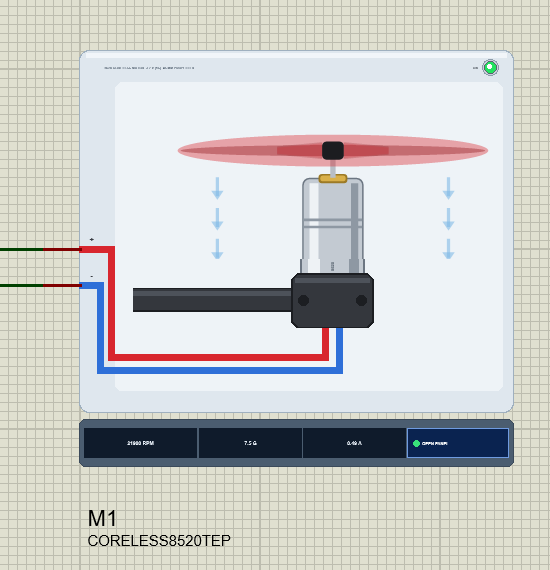
Search coreless or 8520 in Pick Devices; the device CORELESS8520TEP is in TEPCORELESS.LIB (category Electromechanical, Motors) and its model is TEPCORELESS.DLL. It is drawn from the side, upright in the clamp at the end of a drone's arm: the silver can with its brass bearing and the shaft, the red two-blade propeller on its black hub, and the red (+) and blue (-) leads running from the can's foot to the pins.
At Run the propeller turns: slowly, you see the blades swing round; fast, they become a red blur, as your eye sees a real propeller. Arrows beside the motor show the air it pushes - down with the thrust, and up when the motor runs backwards. The ON LED lights green while current flows, and the strip under the plate shows the speed, the thrust, the current and the OPEN PANEL button. The plate, the LED, the air arrows, the rating line and the strip are TEP additions; the real motor has none of them.
The Pins and the Property
| Pin | What the model does with it |
|---|---|
| + | the red lead: the windings' start (positive for the forward direction) |
| - | the blue lead: the windings' end |
| Property | Default | What it does |
|---|---|---|
| PROP | 46 | the propeller: 46 or 55 (mm), or NONE for the bare motor |
Download 8520 Coreless Motor Library for Proteus
Click the button below to download 8520-Coreless-Motor-Library-for-Proteus-v1.0.zip (about 1.3 MB, without the source code of the models):
8520 Coreless Motor Library for Proteus V1.0- README.txt: installation, the demo, the wiring, the property, real hardware, troubleshooting and the limits.
- Proteus Library Files:
TEPCORELESS.LIBandArduinoV4TEP.LIBfrom our Arduino Library for Proteus V4.0. - Proteus Model Files:
TEPCORELESS.DLLandTEPARDUINO.DLL. - Proteus Simulation:
Coreless-Motor-TB6612-ArduinoUnoV4.pdsprj,Coreless_Demo.hexand copies of the two DLLs. - Arduino Code:
Coreless_Demo.ino(no library needed).
Good to know: the demo's driver is our TB6612FNG Motor Driver, a separate library that is not in this zip. Download it from its own article, the TB6612FNG Motor Driver Library for Proteus, and install TEPTB6612.LIB and TEPTB6612.DLL the same way.
No Proteus yet? Read How to Download and Install Proteus 7 and 8. New to libraries? Follow How to Install a New Library in Proteus.
How to Install 8520 Coreless Motor Library for Proteus
- Close Proteus and extract the whole zip file, for example to your Desktop.
- Copy
TEPCORELESS.LIBandArduinoV4TEP.LIBfrom Proteus Library Files into the LIBRARY folder of Proteus (usuallyC:\Program Files (x86)\Labcenter Electronics\Proteus 8 Professional\LIBRARY). - Copy
TEPCORELESS.DLLandTEPARDUINO.DLLfrom Proteus Model Files into the MODELS folder. The two Arduino files are the ones of our Arduino Library V4.0; if you have it, they are the same. - Install the TB6612FNG library the same way if you do not have it yet.
- Delete
TEPCORELESS.IDXfrom the LIBRARY folder if it is there. - Start Proteus, press P and search for coreless.
Tip: keep the Proteus Simulation folder together, because the project needs its .hex file and the DLLs beside it. The library is tested in Proteus 8.5; Proteus 7 is not supported.
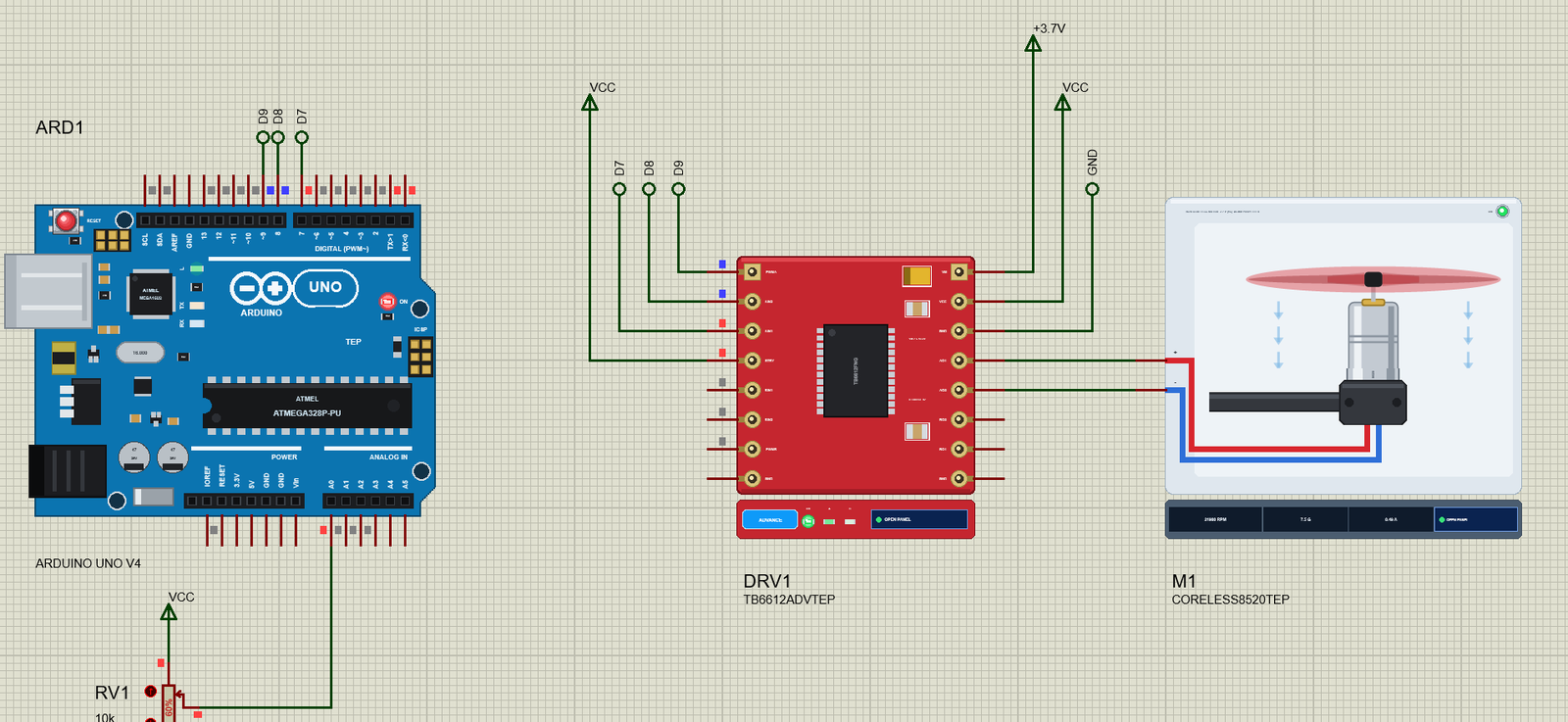
The Demo Circuit
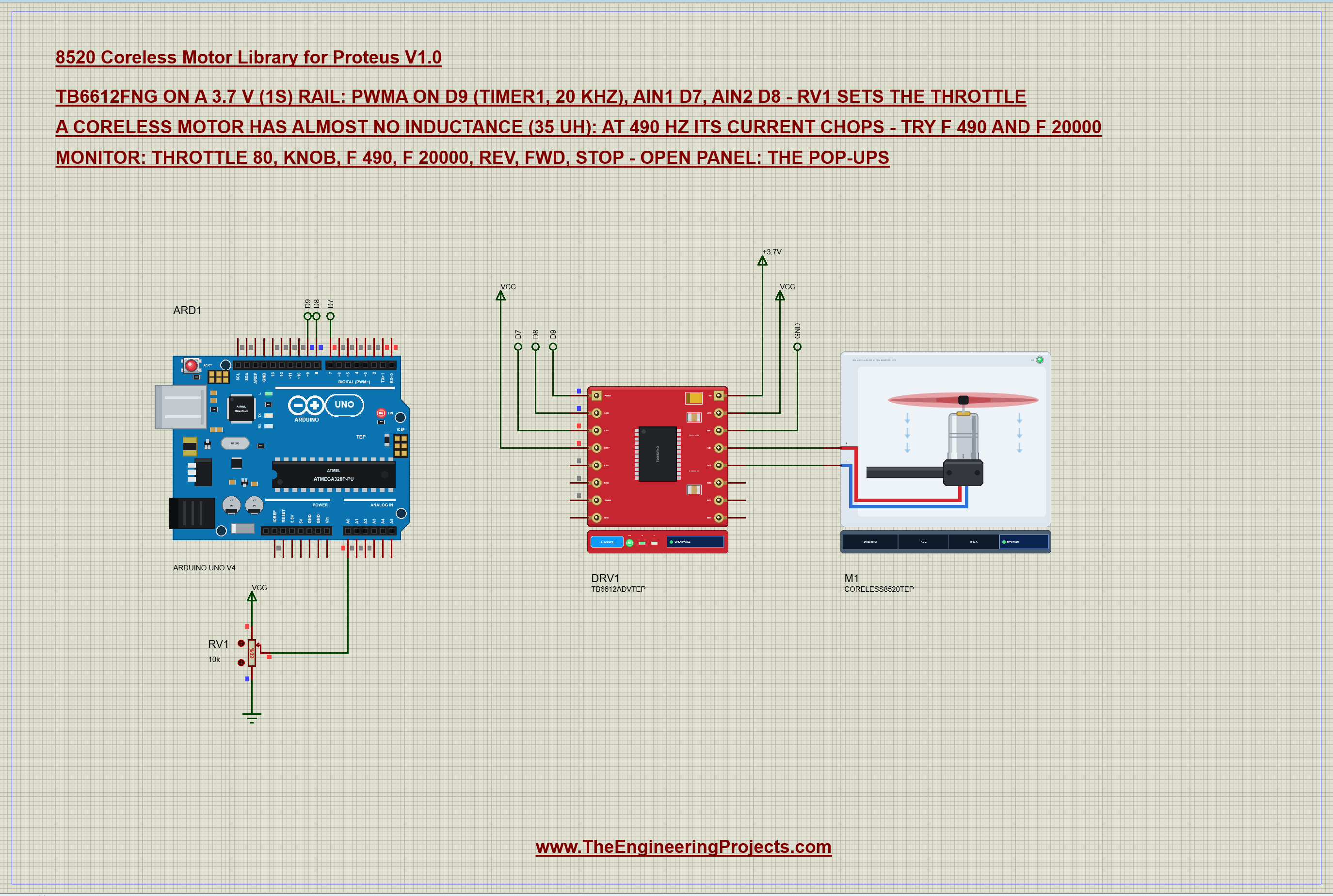
Open Coreless-Motor-TB6612-ArduinoUnoV4.pdsprj. ARD1 is an Arduino UNO V4.0 from our Arduino UNO Library for Proteus V4.0, running Coreless_Demo.hex with its serial monitor built in. DRV1 is our TB6612FNG driver in its pop-up version, its motor supply VM on a +3.7V rail - a 1S LiPo, the micro drone's battery. M1 is the motor on the driver's motor A outputs, and RV1 is a 10k pot on A0: the throttle.
| Part | Pin | Goes to |
|---|---|---|
| TB6612FNG | PWMA, AIN2, AIN1 | D9, D8, D7 (by net labels) |
| TB6612FNG | STBY, VCC | VCC (5 V) |
| TB6612FNG | VM, GND | +3.7V, ground |
| TB6612FNG | AO1, AO2 | the motor's + and - (straight wires) |
| RV1 | wiper | A0 |
Why a TB6612FNG?
An 8520 draws about 1 A at full throttle and 3 to 4 A for a moment when it starts - far beyond any Arduino pin. The TB6612FNG is a small dual H-bridge with MOSFET switches: 1.2 A continuous and 3.2 A peak per channel, a motor supply from 2.5 to 13.5 V (so a single LiPo cell works), and PWM inputs that take up to 100 kHz. A single logic-level MOSFET with a Schottky diode would do for one direction; the TB6612FNG also lets the demo run the motor backwards and brake it.
The Arduino Code
The sketch needs no library. New to Arduino? Start with Arduino Tutorial for Beginners and Introduction to Arduino UNO. The pins come first:
const byte PWMA = 9, AIN1 = 7, AIN2 = 8;      // TB6612FNG motor A (STBY on VCC)
const byte KNOB = A0;
analogWrite() cannot make 20 kHz, so the sketch sets Timer1 itself: fast PWM mode 14, where the ICR1 register sets the period. With no prescaler, an ICR1 of 799 gives 16 MHz / 800 = 20 kHz; for the slow test it divides by 8 and uses 4080 for 490 Hz:
void setFreq(unsigned long f) {               // Timer1 fast PWM, TOP = ICR1 (mode 14)
  freq = f;
  TCCR1A = _BV(WGM11);
  if (f >= 1000) { TCCR1B = _BV(WGM13) | _BV(WGM12) | _BV(CS10); ICR1 = 16000000UL / f - 1; }   // no prescaler: 20 kHz = 799
  else { TCCR1B = _BV(WGM13) | _BV(WGM12) | _BV(CS11); ICR1 = 2000000UL / f - 1; }              // / 8: 490 Hz = 4080
  apply();
}
The throttle becomes the compare value OCR1A, a fraction of the period. At 0 % and 100 % the sketch drives the pin itself instead, because the timer would still put a one-clock spike into every period:
  if (throttle == 0 || throttle >= 100) {     // 0 % and 100 %: the pin itself, not the timer
    TCCR1A &= ~_BV(COM1A1);
    digitalWrite(PWMA, throttle ? HIGH : LOW);
  } else {
    OCR1A = (unsigned long)(ICR1 + 1) * throttle / 100;
    TCCR1A |= _BV(COM1A1);                    // OC1A on D9: high from the start of each period to OCR1A
  }
AIN1 and AIN2 set the direction - HIGH and LOW for forward, the other way round for reverse:
  digitalWrite(AIN1, reverse ? LOW : HIGH);
  digitalWrite(AIN2, reverse ? HIGH : LOW);
Both HIGH is the TB6612FNG's short brake: both outputs to ground, so the motor's own back-EMF stops it quickly:
digitalWrite(PWMA, HIGH); digitalWrite(AIN1, HIGH); digitalWrite(AIN2, HIGH);In knob mode, RV1 sets the throttle every 100 ms, and the sketch reports it when it moves by 2 % or more:
    const byte k = (unsigned long)analogRead(KNOB) * 100 / 1023;
    if (abs((int)k - (int)throttle) >= 2) { throttle = k; apply(); report(); }
The commands set a fixed throttle, the PWM frequency and the direction:
if (!strncmp(s, "f ", 2)) { setFreq(constrain(atol(s + 2), 100L, 40000L)); report(); return; }and the direction is one flag that apply() turns into AIN1 and AIN2:
if (!strcmp(s, "rev")) { reverse = true; apply(); report(); return; }The HEX file is in the package. To change the sketch, open it in the Arduino IDE and export the compiled binary, as in How to get the HEX file from Arduino. It needs 6,248 bytes of flash (19 % of the UNO) and 284 bytes of RAM.
Running the Demo
Press Run. The UNO's serial monitor, the motor's pop-up and the TB6612FNG's pop-up open over the schematic; move them aside. RV1 starts at 60 %, so the motor spins up at once:
8520 Coreless Motor demo - The Engineering Projects
TB6612FNG on 3.7 V: PWMA D9 (Timer1, 20 kHz), AIN1 D7, AIN2 D8. RV1 sets the throttle.
Commands: throttle 80 | knob | f 490 | f 20000 | rev | fwd | stop | help
Throttle 60 % at 20.0 kHz, forward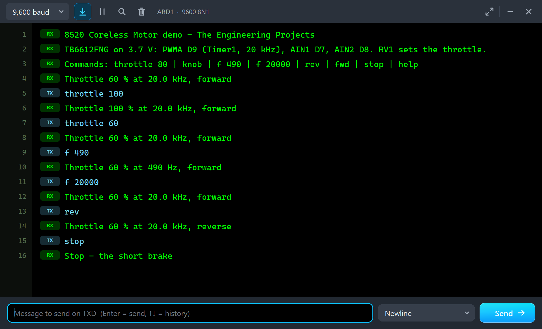
Within a quarter of a second the motor is at speed - a coreless rotor with a small propeller is that quick. The Event log writes the drive, "PWM 20.0 kHz = 1.97 V average across the motor (forward)", and then "STEADY - 21974 RPM, 7.5 g of thrust, 0.49 A (0.57 A RMS) at 1.98 V". Note the two currents: the average, 0.49 A, and the RMS, 0.57 A. At 20 kHz they are close together - the current ripples a little with each pulse, but stays smooth.
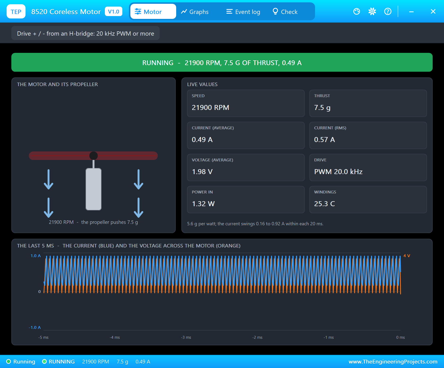
The pop-up has the look of our TEP Serial Monitor Advance for Proteus and four tabs: Motor, Graphs, Event log and Check. The Motor page shows the state in big letters - here "RUNNING - 21900 RPM, 7.5 G OF THRUST, 0.49 A" - then the motor with its propeller and the air, and eight live values: the speed, the thrust, the current's average and RMS, the voltage, the drive, the power in and the windings' temperature. A line under them gives the efficiency: 5.6 g of thrust per watt.
The bottom of the page is a scope of the last 5 milliseconds: the voltage across the motor in orange and the current in blue. At 20 kHz that is a hundred PWM periods: the voltage switches between the supply and zero, and the current rides between 0.16 and 0.92 A - a fine sawtooth around its average.
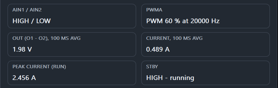
The TB6612FNG's pop-up sees the same from the driver's side: PWMA at 60 % and 20,000 Hz, 1.98 V and 0.489 A on motor A, and a peak of 2.456 A from the moment the motor started - a coreless motor's inrush, which is why the driver needs its 3.2 A peak rating.
Full Throttle
Type throttle 100:
throttle 100
Throttle 100 % at 20.0 kHz, forward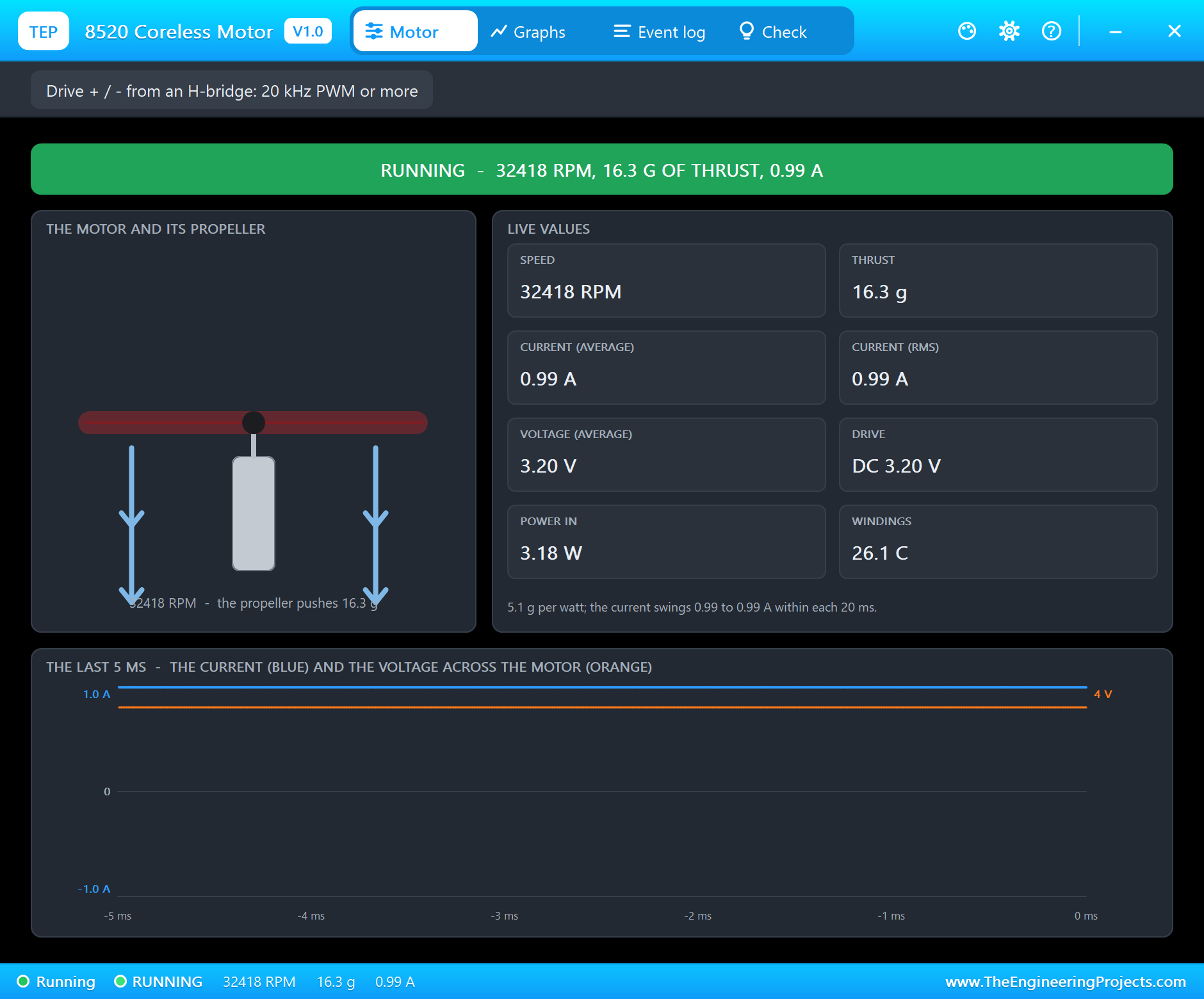
At 100 % there is no PWM at all - the sketch drives PWMA high - and the log says "steady 3.20 V across + / - (forward)" and "STEADY - 32412 RPM, 16.3 g of thrust, 0.99 A (0.99 A RMS) at 3.20 V". The motor gets 3.2 V rather than 3.7 V because the TB6612FNG's switches drop about half a volt at 1 A. With steady DC the average and the RMS current are the same: there is nothing to chop.
The 490 Hz Test: a Chopped Current
Now the classic mistake. Go back to 60 % and switch the PWM to the 490 Hz of analogWrite():
throttle 60
Throttle 60 % at 20.0 kHz, forward
f 490
Throttle 60 % at 490 Hz, forward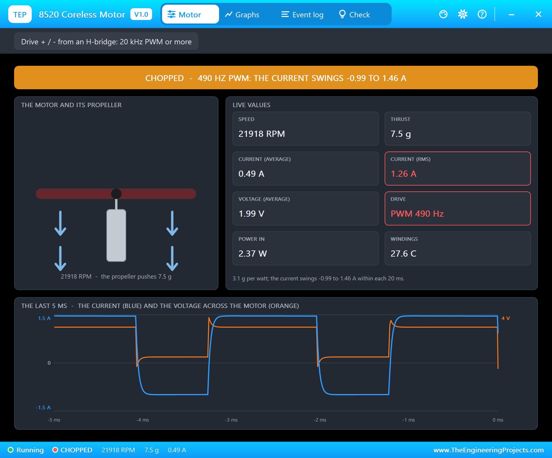
The status turns amber: "CHOPPED - 490 HZ PWM: THE CURRENT SWINGS -0.99 TO 1.46 A". The scope shows why. Each 1.2 ms pulse is long enough for the current to climb all the way to 1.46 A, and each 0.8 ms gap - the TB6612FNG brakes the motor between pulses - is long enough for the back-EMF to push it all the way to -0.99 A. The motor is driven and braked 490 times a second.
Compare the numbers with the 20 kHz run. The speed is the same, 22,023 RPM against 21,974; the thrust is the same, 7.5 g; the average current is the same, 0.47 A. But the RMS current is 1.26 A instead of 0.57 A, the power in is 2.37 W instead of 1.32 W, and the efficiency falls from 5.6 to 3.1 g per watt. On a drone that is a shorter flight, a hotter motor and a high whine.
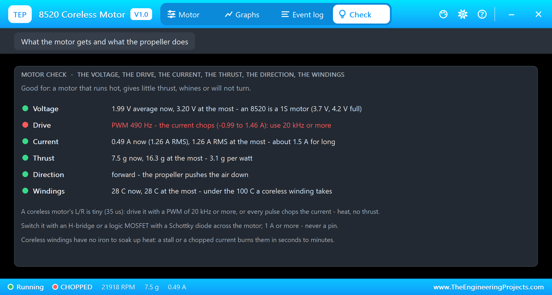
The log has the warning: "CHOPPED CURRENT - PWM 490 Hz: it swings -0.99 to 1.46 A every pulse (L/R 35 us); use 20 kHz". The Check page goes through the voltage, the drive, the current, the thrust, the direction and the windings, each with a coloured dot; here the Drive row is red, and its tips explain the cure: a PWM of 20 kHz or more.
Running Backwards
Back to 20 kHz, and then the reverse:
f 20000
Throttle 60 % at 20.0 kHz, forward
rev
Throttle 60 % at 20.0 kHz, reverse
stop
Stop - the short brake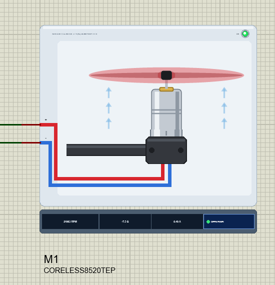
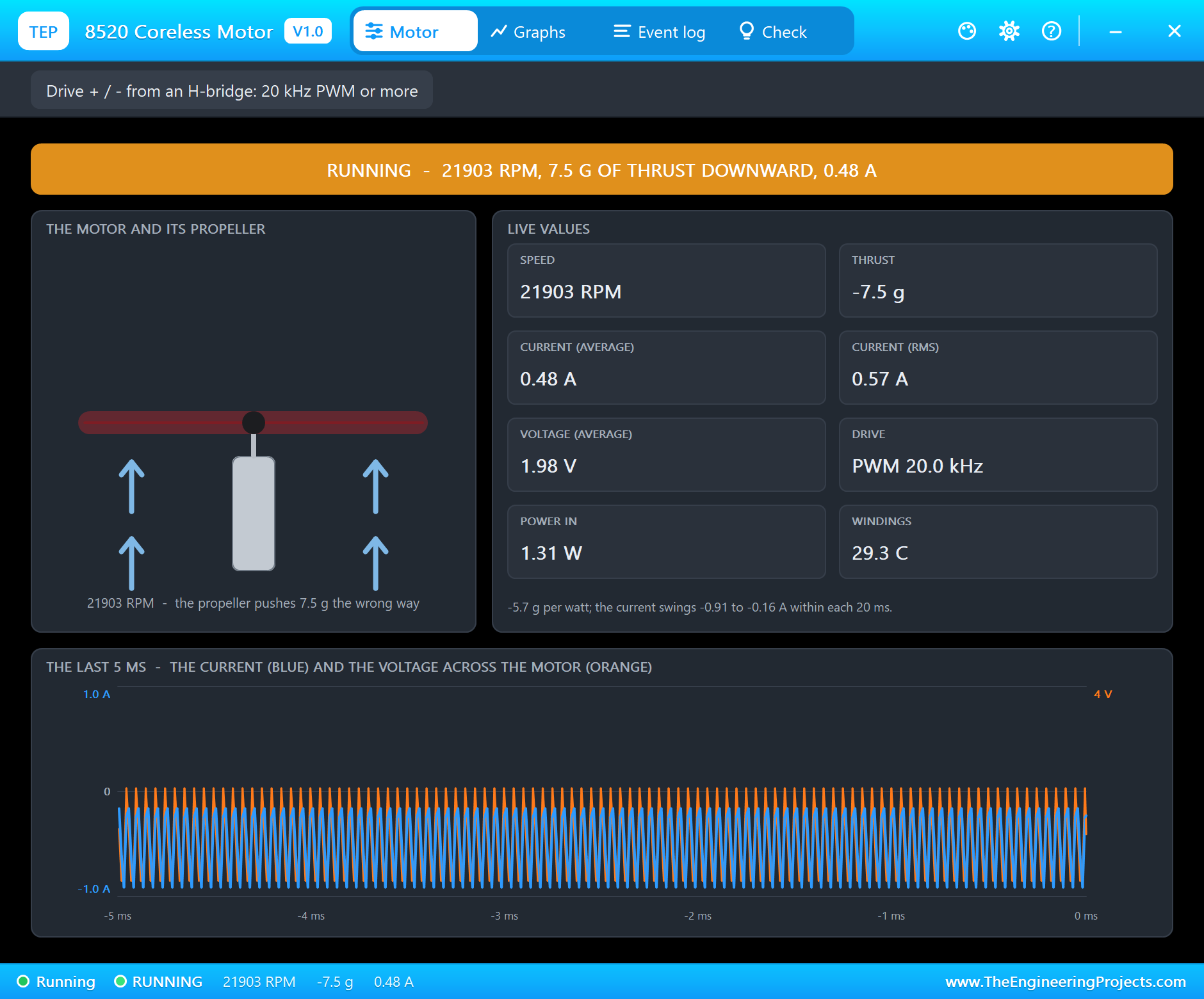
rev swaps AIN1 and AIN2, the motor slows, stops and spins up the other way: "STEADY - 21907 RPM, -7.5 g of thrust DOWNWARD", followed by "REVERSED - the propeller pushes the air the other way: 7.5 g downward". On the sheet the air arrows turn round. On a drone, a motor wired the wrong way round, or a propeller fitted upside down, does exactly this - the drone flips on take-off. Finally stop applies the short brake, and the log ends with "drive off: + and - at the same level (coasting or braking)".
Graphs and the Log
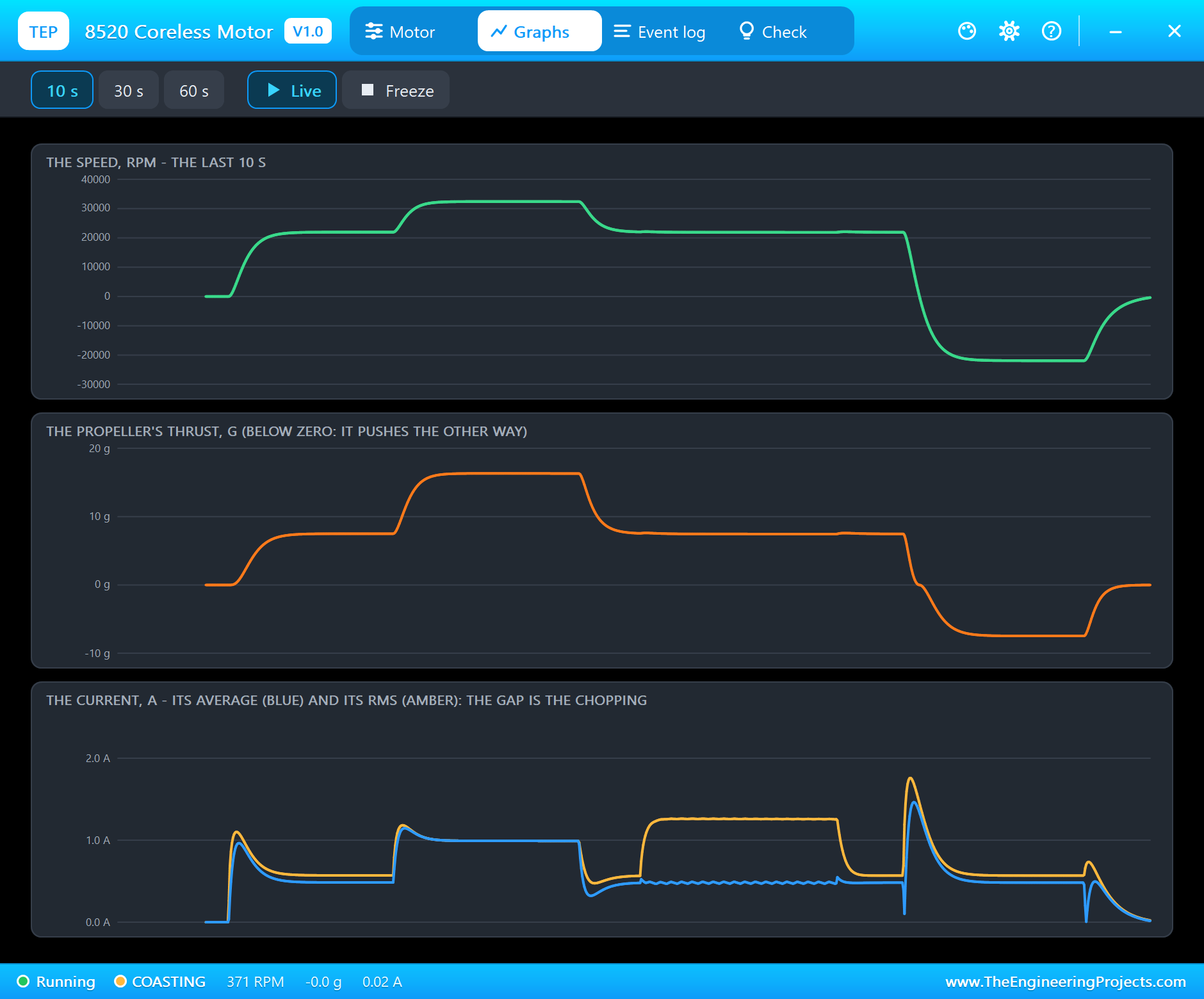
Graphs draws the speed, the thrust and the current over the last 10, 30 or 60 seconds. The 10 s view holds the whole demo: the start, full throttle, back to 60 %, the reverse below zero and the stop. The current graph is the one to watch: the blue average and the amber RMS lie on top of each other, except in the 490 Hz stretch, where the RMS jumps to 1.26 A while the average stays at 0.47 A. That gap is the chopping.
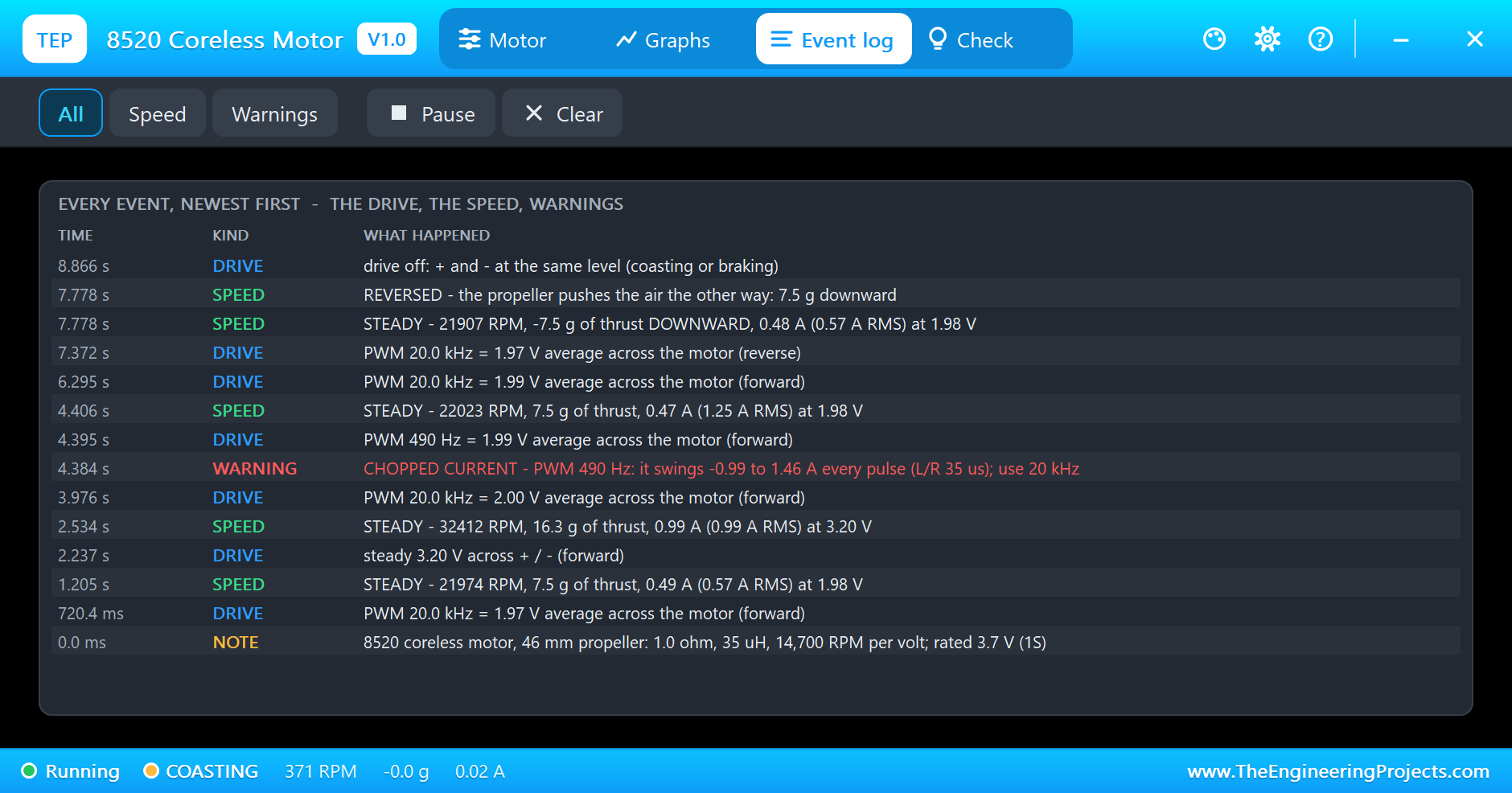
The Event log keeps every drive change with its frequency and average voltage, every steady speed with its thrust and its currents, and every warning with its reason. Filter it to Speed or Warnings, pause it, or clear it.
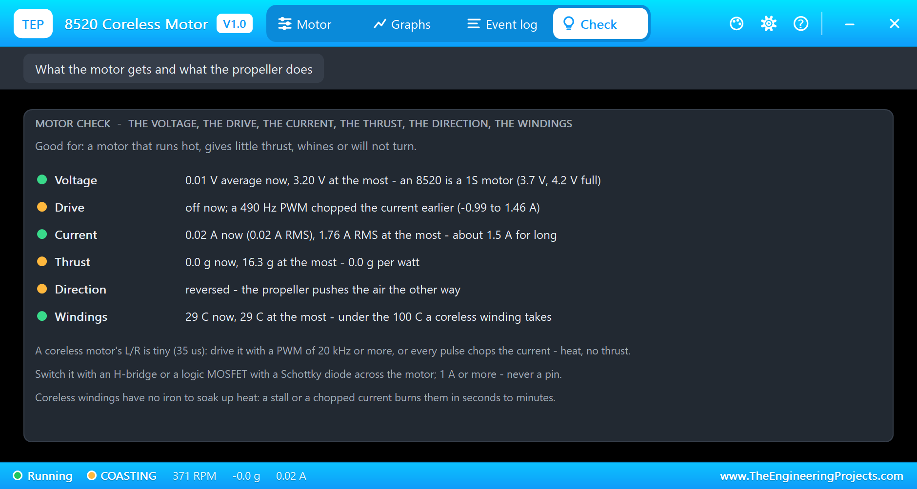
At the end of the run the Check page sums it up: 3.20 V at the most, within the 1S rating; the Drive row amber because a 490 Hz PWM chopped the current earlier; 16.3 g of thrust at the most; and the windings at 29 C. The demo was short; leave a coreless motor chopping for minutes, and the windings would tell a different story.
How the Model Works
The windings sit between + and - as 1.0 ohm and 35 uH in series with the back-EMF, 0.65 mV for every rad/s of the rotor. At every analog step the model puts a conductance and a current source into the circuit that stand for that branch, so the driver and the motor are solved together, pulse by pulse. The step is held to 12.5 microseconds while the motor is driven or turning, so it sees every edge of a 20 kHz PWM - which also means a run is slower than real time.
The rotor follows the motor's torque against the friction and the propeller's drag, in sub-steps of at most 20 microseconds. The propeller's thrust and drag grow with the square of the speed (Ct 0.10, Cq 0.008 at its diameter) and change sign when it runs backwards. The windings warm with I squared R, so the RMS current - not the average - sets the temperature.
We checked the model on a PC with 12 automatic tests: at 3.7 V DC through the bridge it runs at 32,416 RPM, 0.99 A and 16.3 g, reaching 90 % of its speed in 243 ms; free it runs at 51,732 RPM on 0.12 A; at 60 % the RMS current is 0.59 A at 20 kHz and 1.27 A at 490 Hz for the same 7.5 g; 5 V gives the OVER-VOLTAGE warning; and 40 s at 80 % warms the windings to 52 C at 490 Hz against 36 C at 20 kHz. The demo project is read back from disk with 69 checks.
Troubleshooting
- It does not turn and nothing is logged: no drive - the TB6612FNG has no VM, STBY is low, or its inputs are not driven.
- CHOPPED CURRENT: the PWM is under 5 kHz - set Timer1 to 20 kHz or more, as the demo does.
- The thrust is negative (REVERSED): swap AIN1 and AIN2, or the motor's leads.
- HOT: a chopped current, a stall or too much voltage - a coreless winding burns out above about 100 C.
- OVER-VOLTAGE: more than 4.2 V average across the motor - it is a 1S motor.
- The motor is not simulated:
TEPCORELESS.DLLis missing from MODELS and from the project folder. - No driver: install our TB6612FNG library (
TEPTB6612.LIBandTEPTB6612.DLL). - No UNO or no monitor:
TEPARDUINO.DLLis missing; a closed monitor opens again with a click on the UNO's USB port.
Things to Know Before Building a Micro Drone
- Use a fast PWM: 20 kHz or more. analogWrite()'s 490 or 980 Hz chops a coreless motor's current: more heat and battery drain, and a whine, for the same thrust.
- Switch it properly: an H-bridge such as the TB6612FNG, or a logic MOSFET (AO3400, SI2302) with a Schottky diode across the motor - an 8520 draws over 1 A, and 3 to 4 A at the start.
- Stay on 1S: a single LiPo cell, 3.7 V and 4.2 V full. 5 V shortens the motor's life.
- Match the propellers: drones use CW and CCW motors (red / blue or black / white leads) with matching propellers; one the wrong way pushes the wrong way.
- Never stall it: a blocked coreless motor has no iron to soak up the heat, and burns out in seconds.
Limitations of the Simulation
- Not modelled: the brushes' arcing and wear, the commutation ripple, the airflow around a frame or near the ground, and the drone around the motor.
- The plate, the ON LED, the air arrows, the rating line and the strip are TEP additions.
- The model is our own, written from the typical data of 8520 coreless motors and small propellers; this library is not made or endorsed by any motor or drone maker, Arduino or Labcenter.
- Licences: the demo HEX contains the Arduino AVR core 1.8.6 (LGPL); the sketch is included and the README gives the source link. The TB6612FNG driver of the demo is our separate library.
- Tested in Proteus 8.5 in October 2026 with the demo as shipped: 60 % at 20 kHz, full throttle, 490 Hz, back to 20 kHz, reverse, the short brake and all four pages of the pop-up. Proteus 7 is not supported.
So, that was all about the 8520 Coreless Motor Library for Proteus V1.0. I hope it helps you with your micro drone, your tiny robot or your flight controller code - and saves a few motors from a 490 Hz PWM. If you have any questions, ask in the comments and I will help you out. Till the next tutorial, take care and have fun!